
Experimental Evaluation of IEEE 802.15.4z UWB Ranging Performance under Interference


Abstract
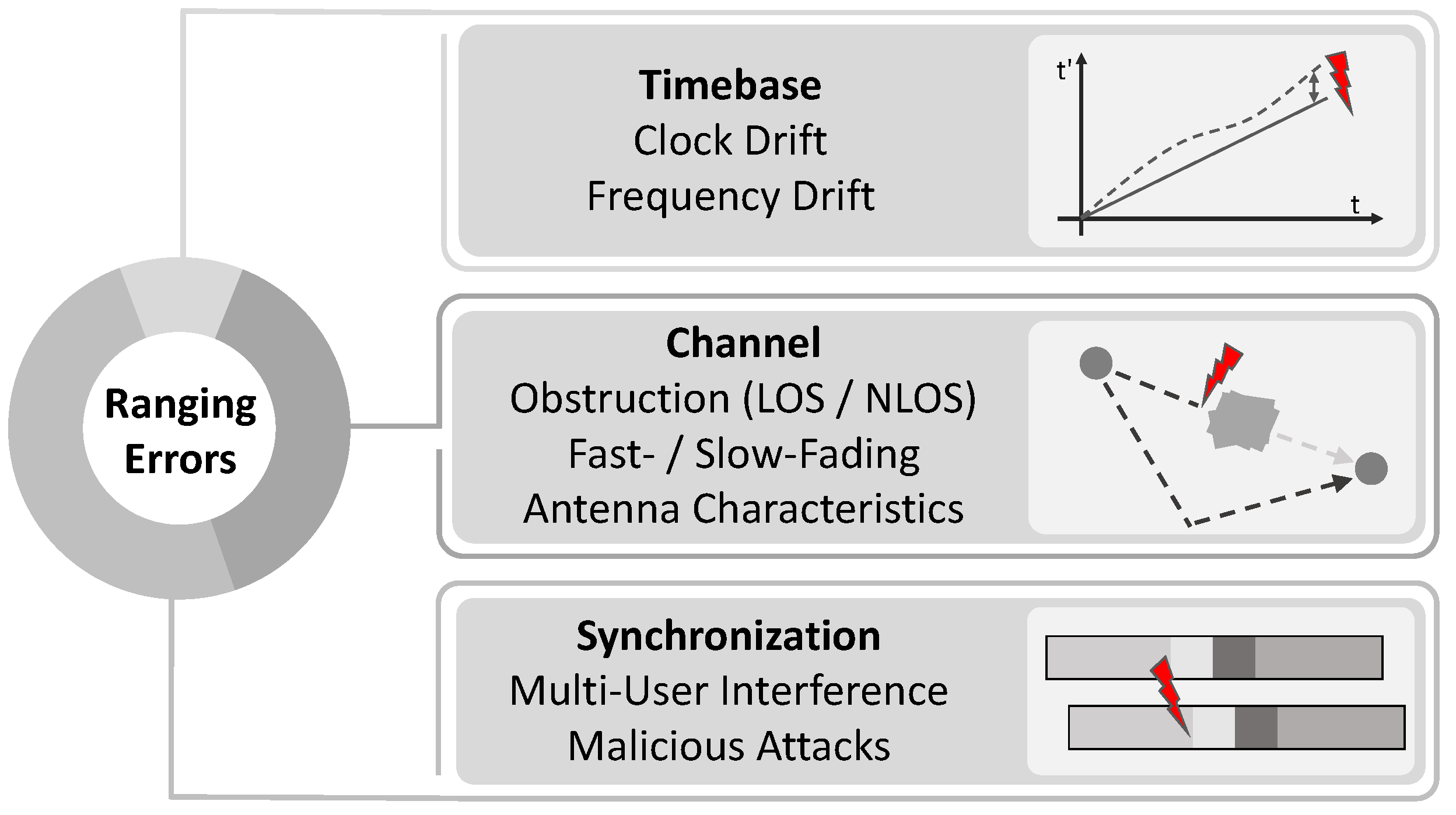
:1. Introduction and Related Work
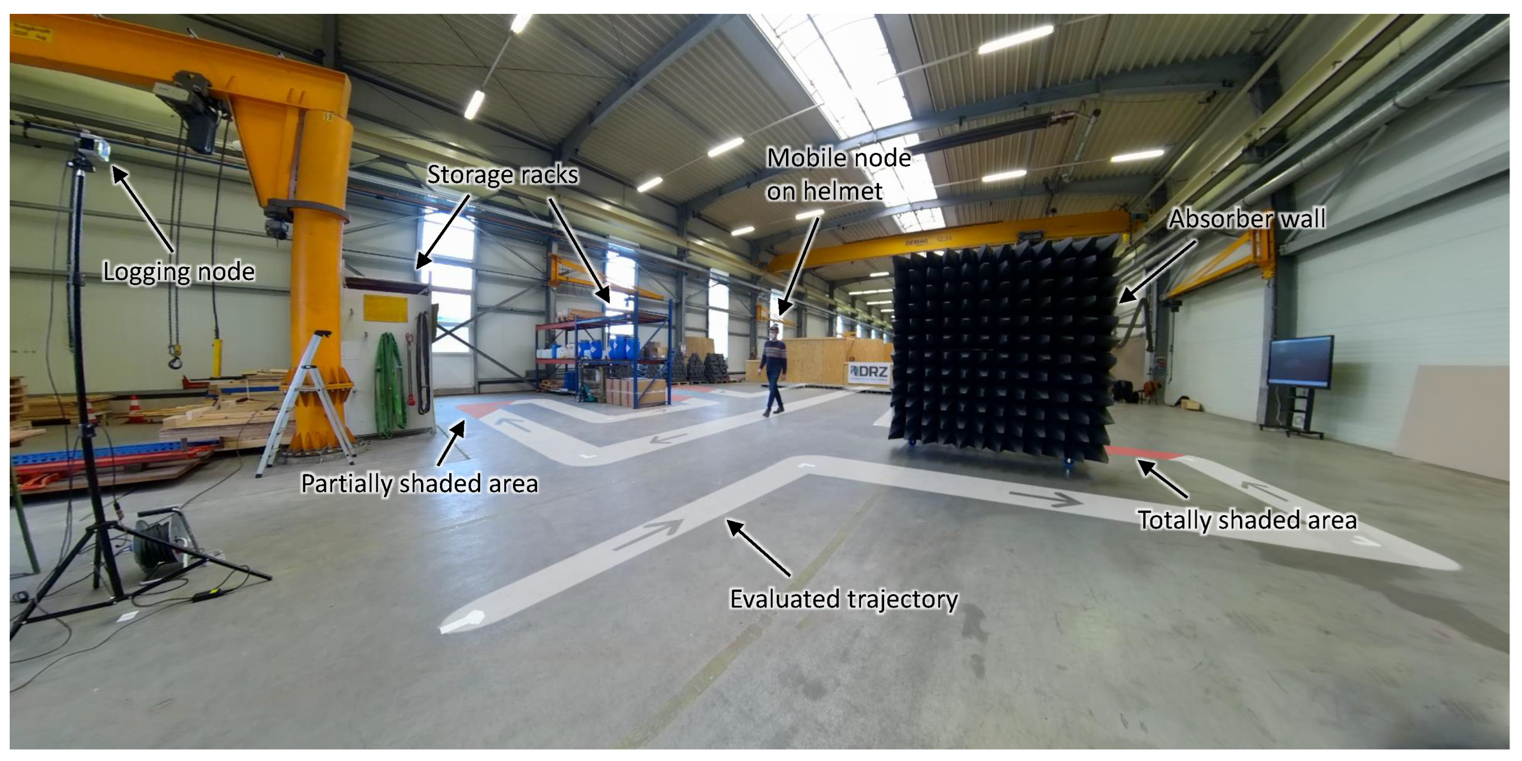
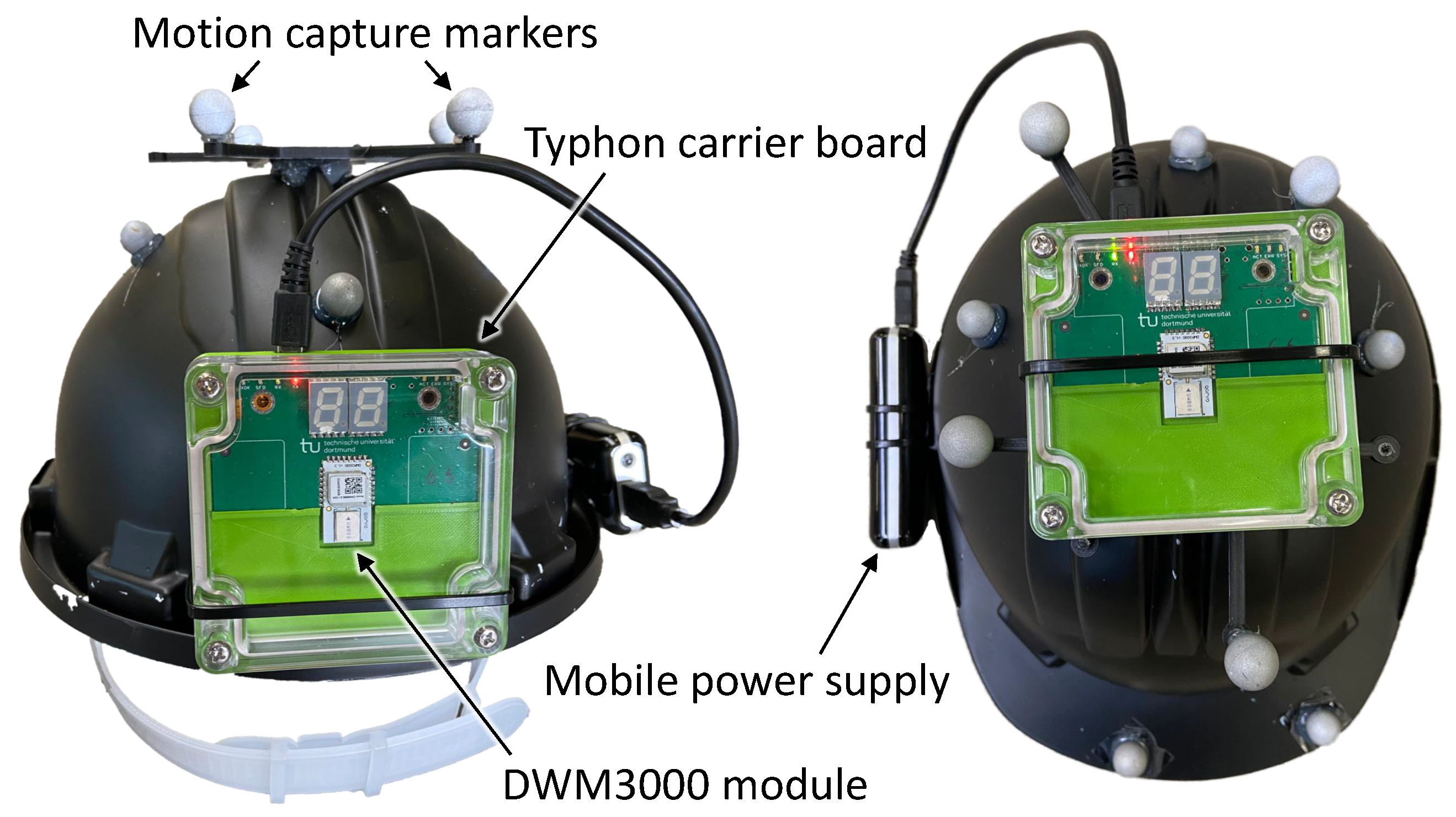
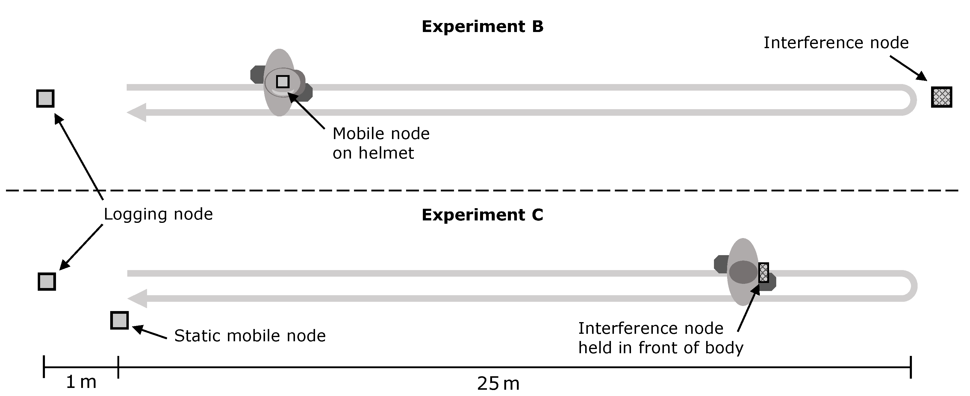
2. Experimental Methodology and Common Parameters
Two-Way Ranging Configurations
3. Experimental Evaluation
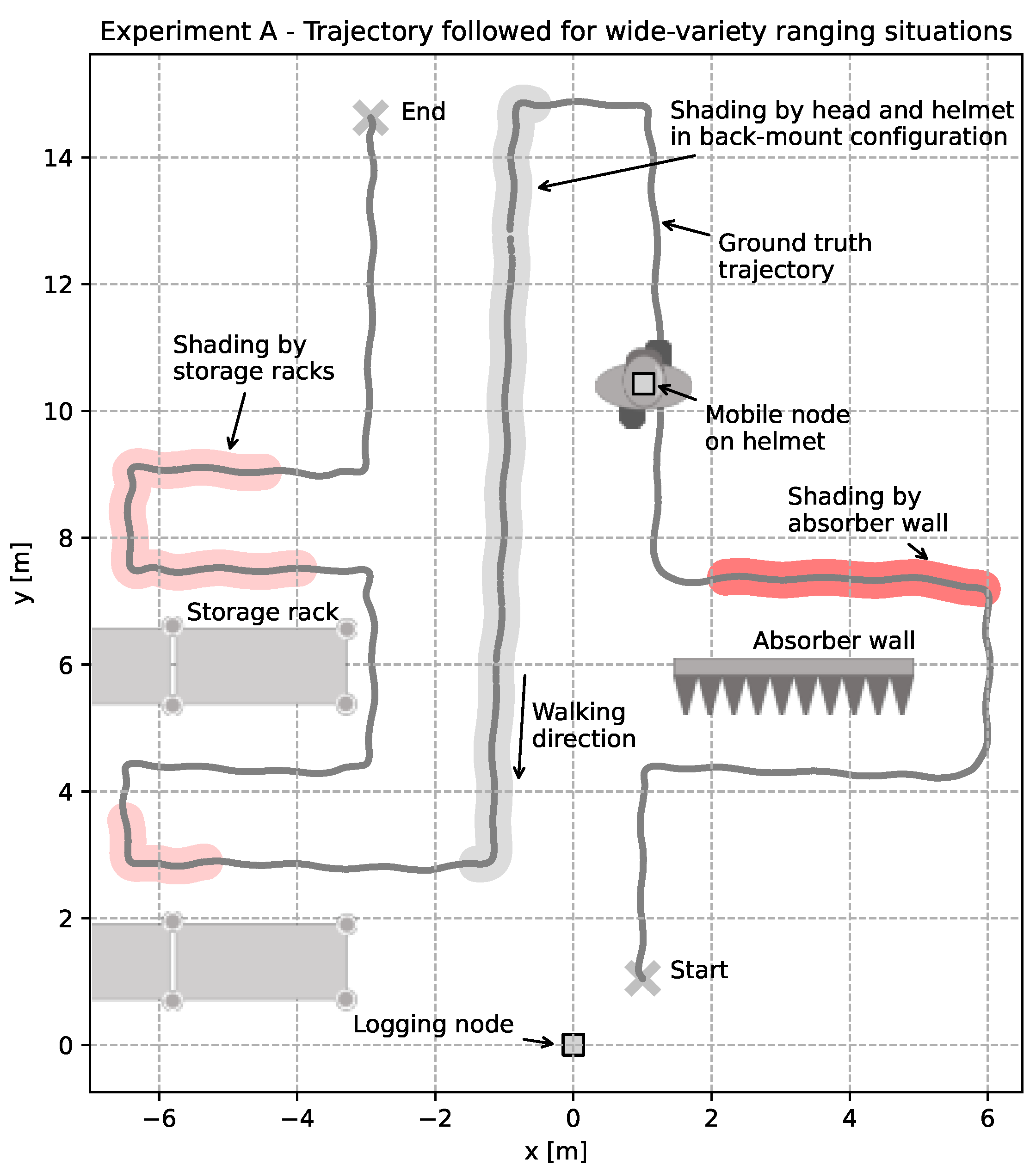
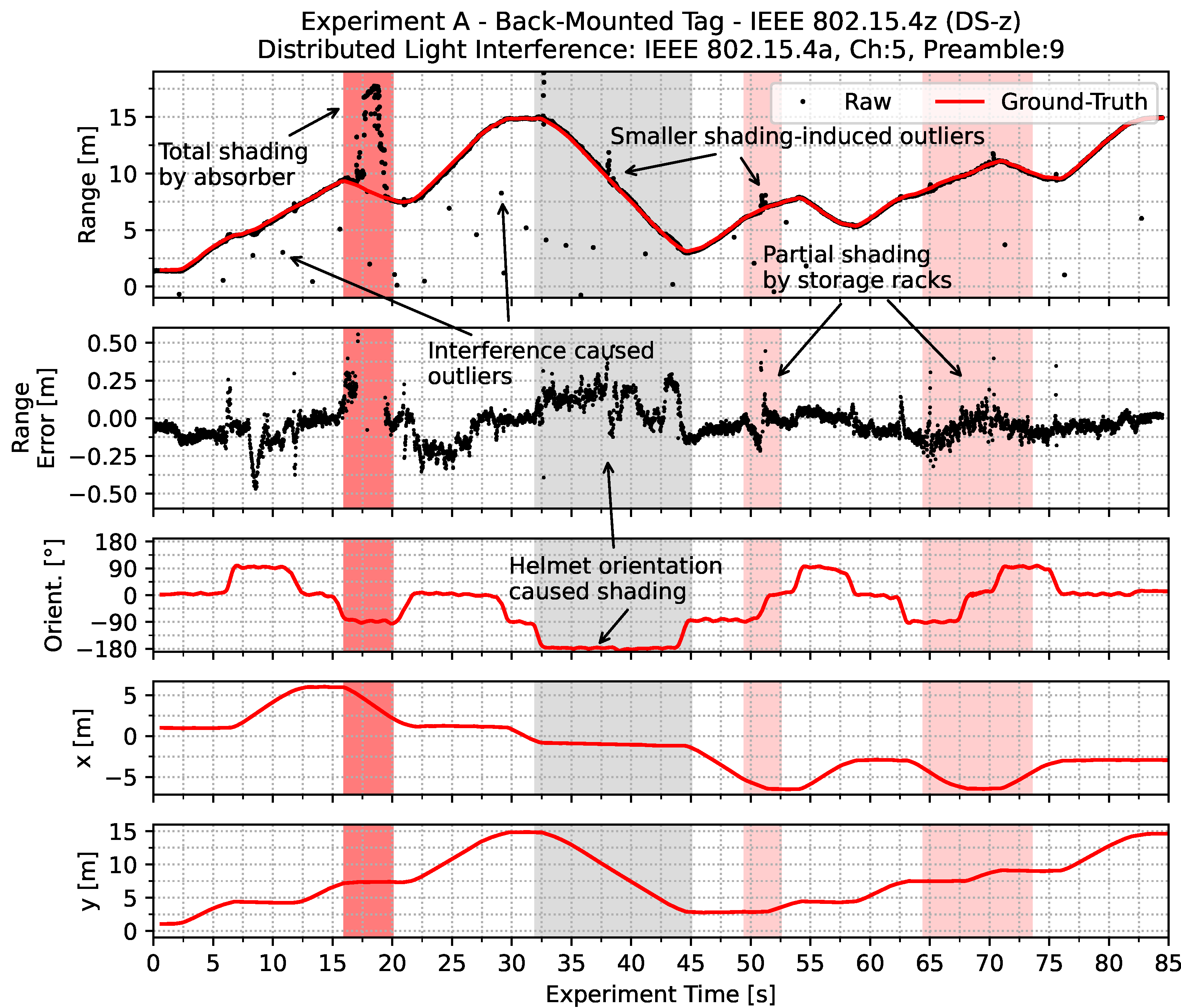
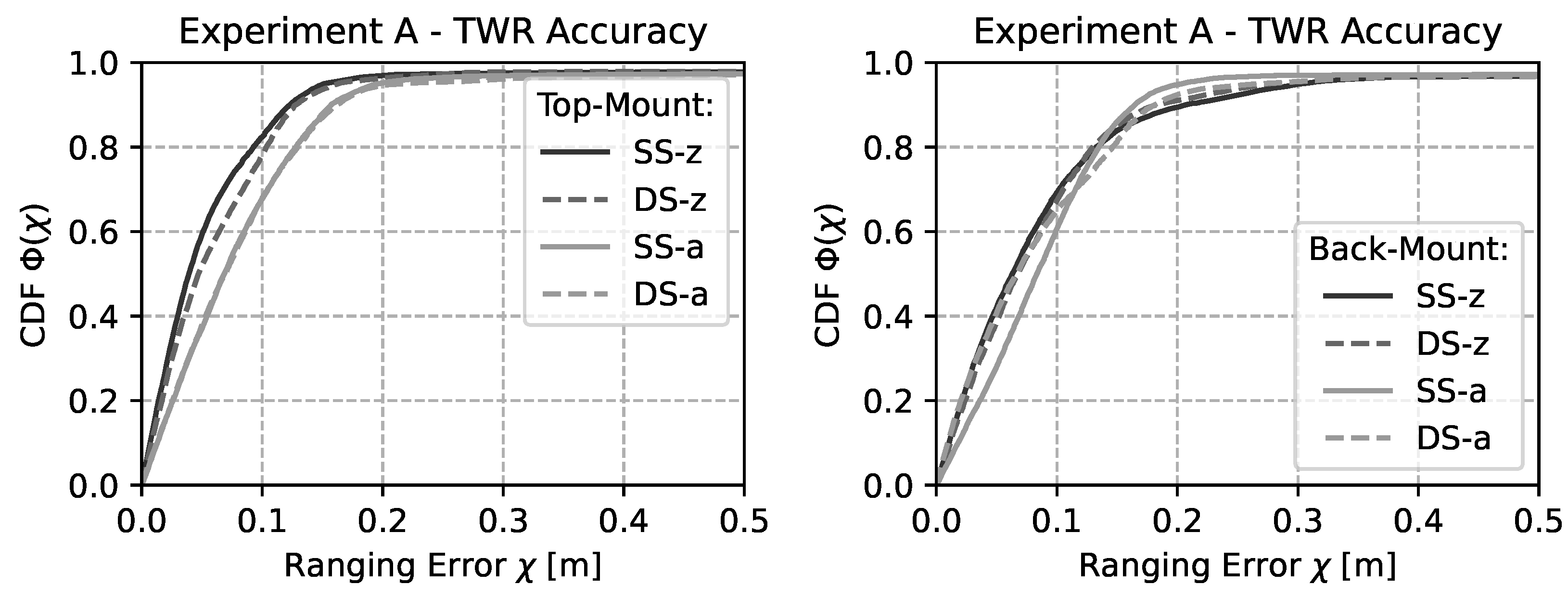
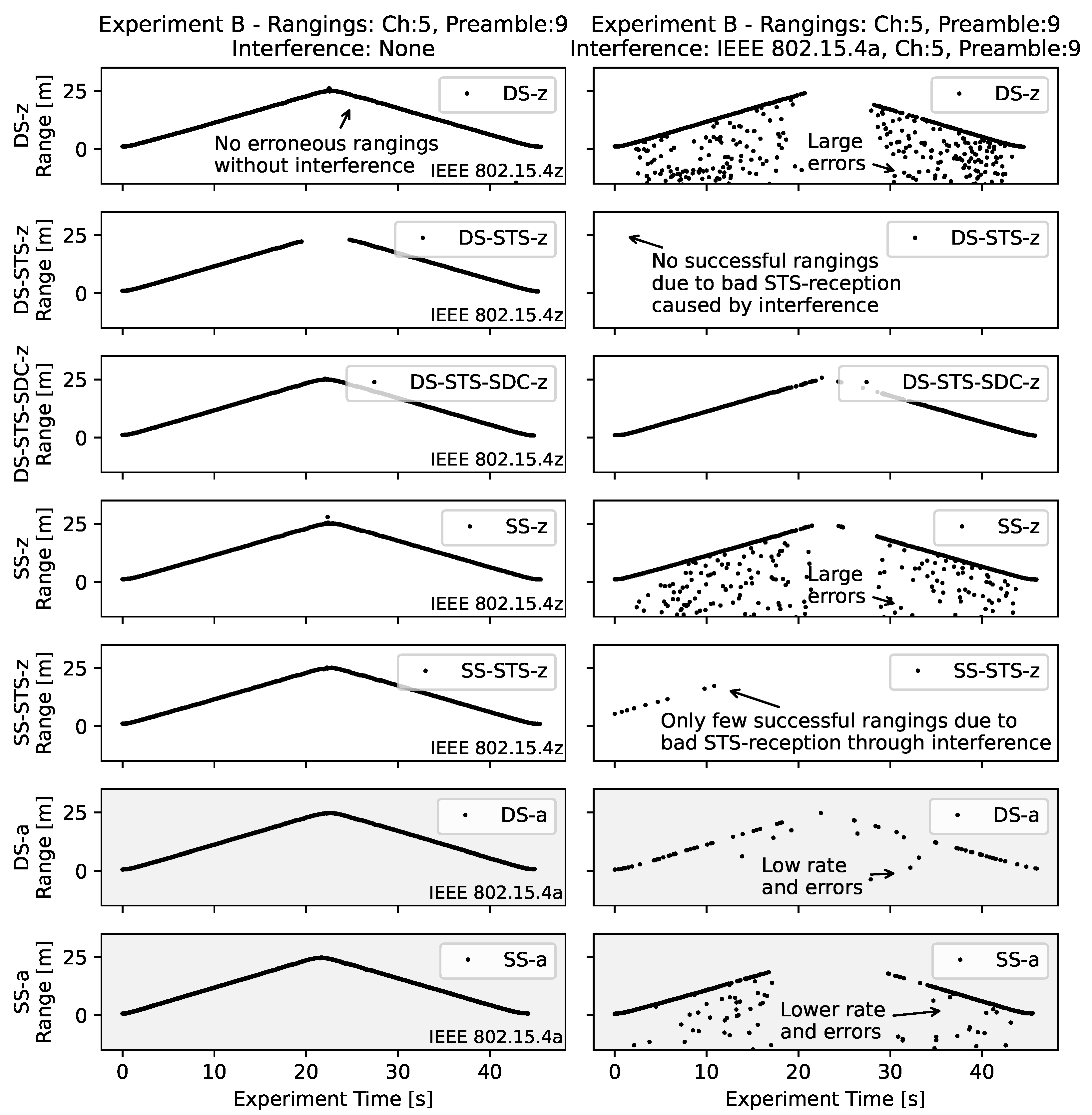
3.1. Dynamic Ranging Accuracy
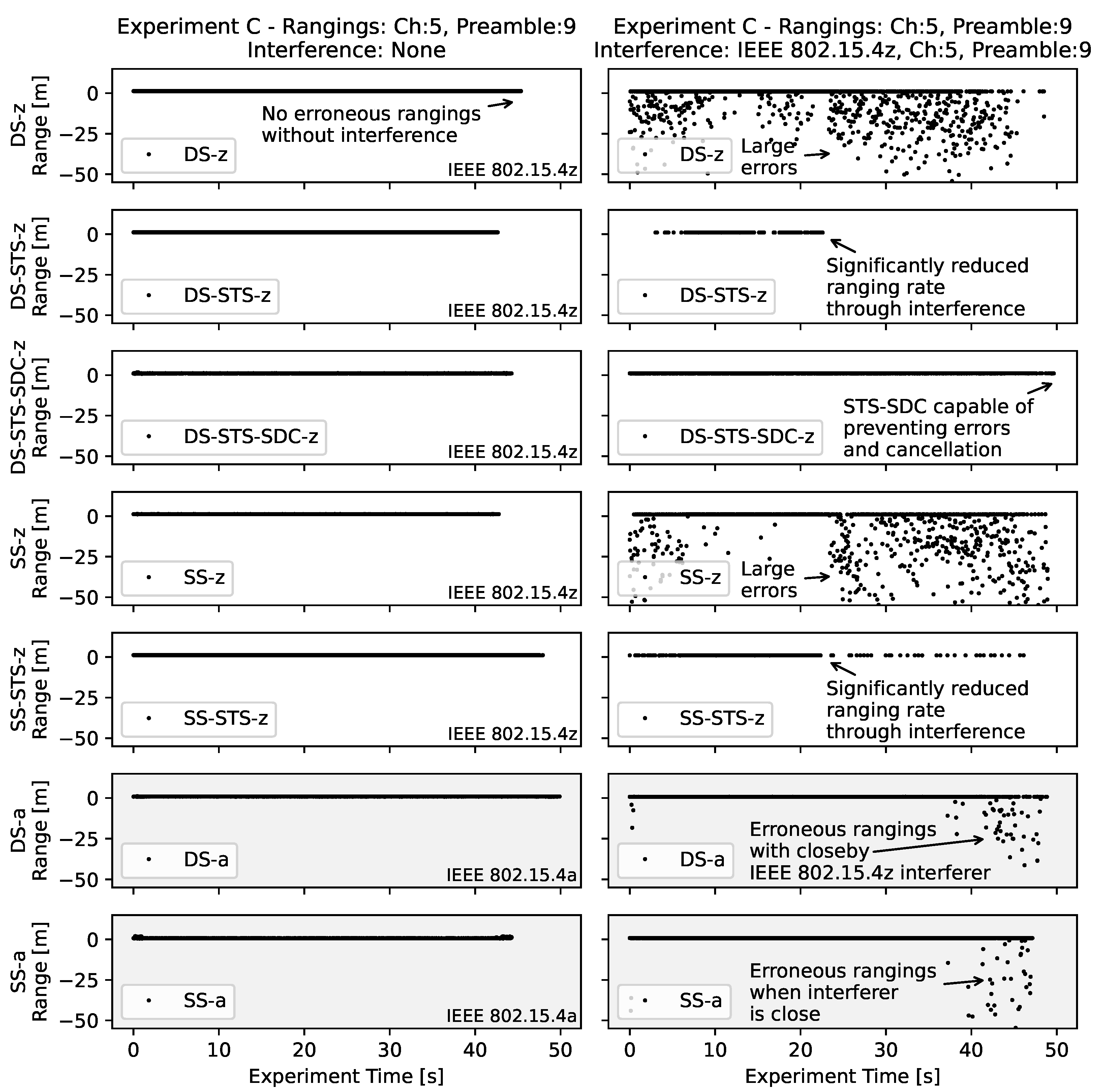
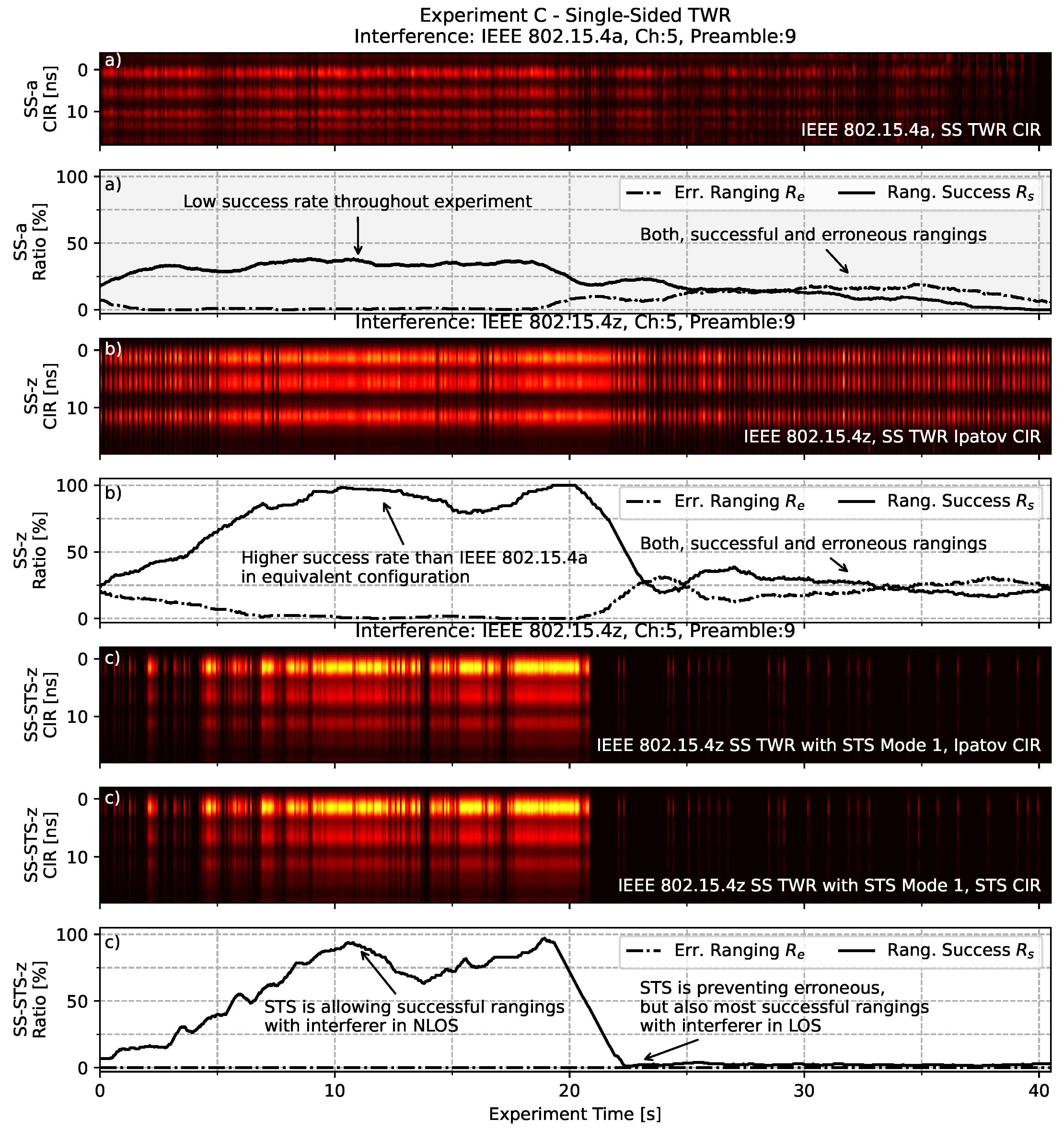
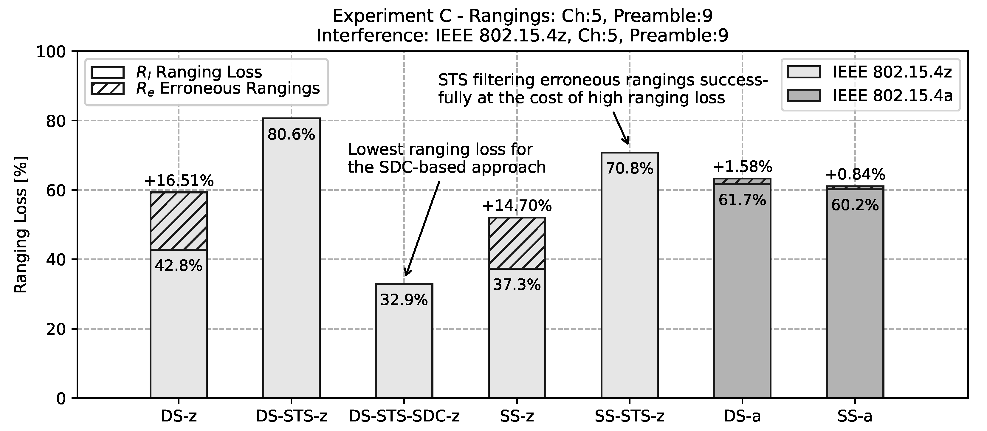
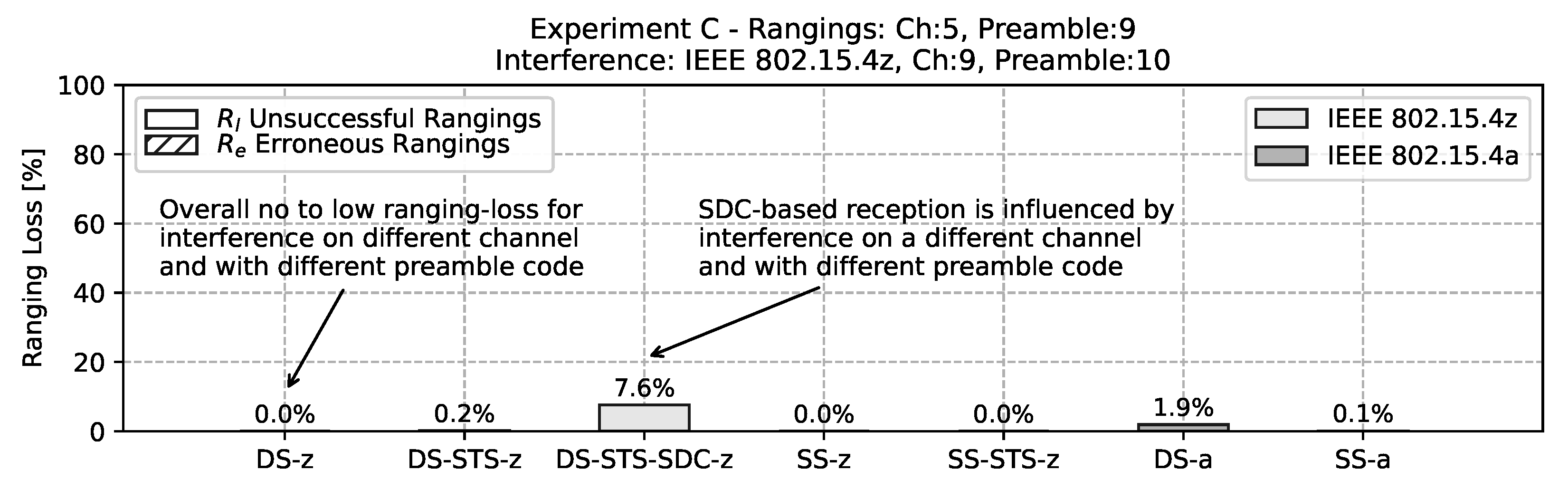
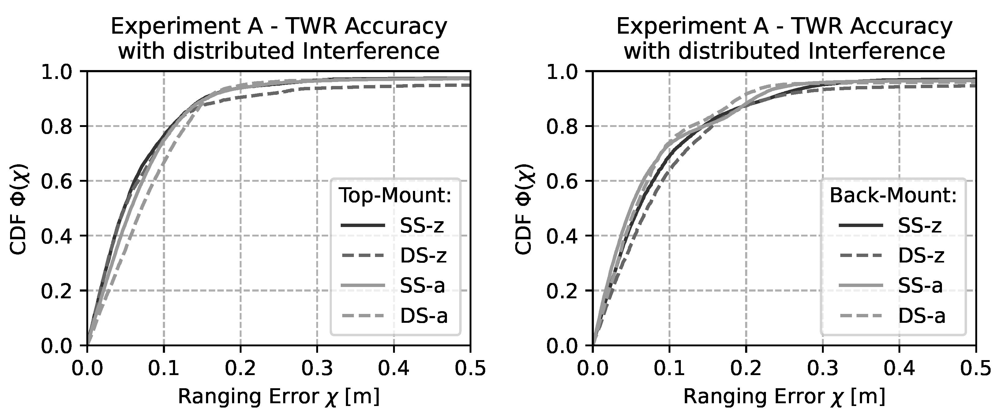
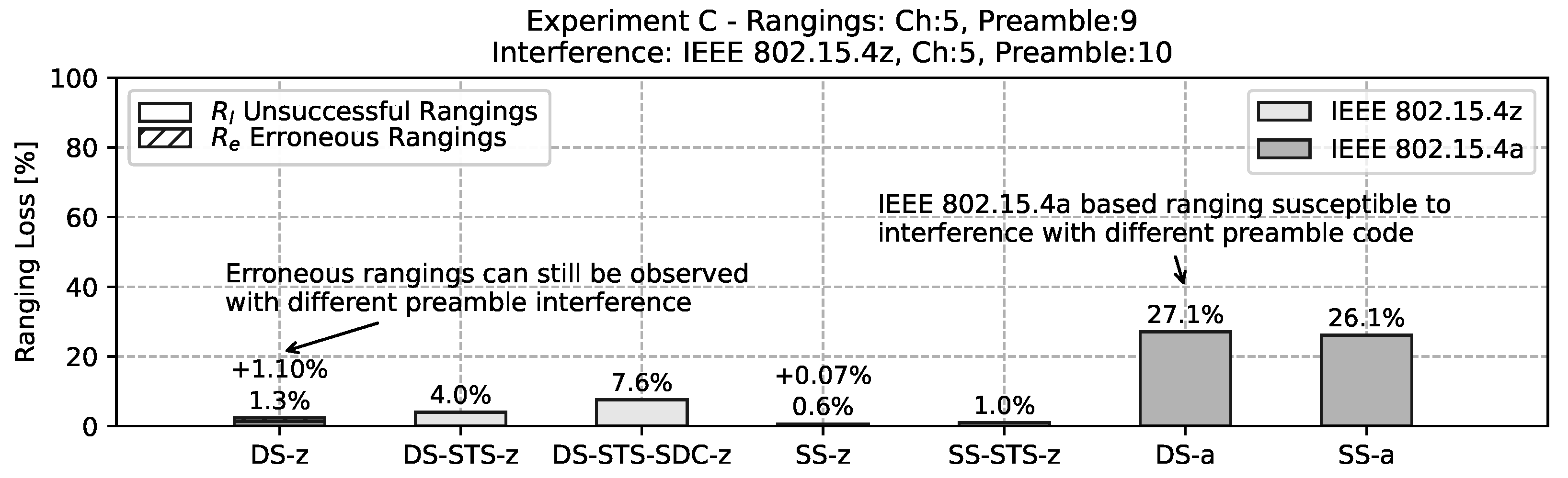
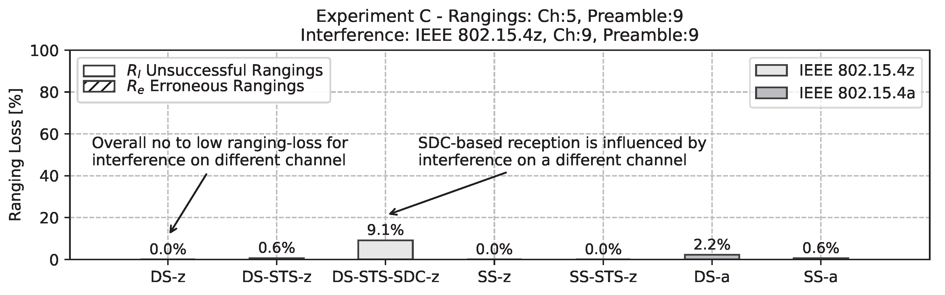
3.2. Controlled Interference
4. Conclusions and Future Work
Author Contributions
Funding
Acknowledgments
Conflicts of Interest
Sample Availability
Abbreviations
| CDF | Cumulative Distribution Function |
| CIR | Channel Impulse Response |
| DS | Double-Sided |
| IEEE | Institute of Electrical and Electronics Engineers |
| NLOS | Non-Line of Sight |
| LOS | Line of Sight |
| PAC | Preamble Acquisition Chunk |
| PHR | Packet Header |
| PHY | Physical Layer |
| PRF | Pulse Repetition Frequency |
| SDC | Super Deterministic Code |
| SFD | Start of Frame Delimiter |
| SS | Single-sided |
| STS | Scrambled Time Sequence |
| SYNC | Synchronization Preamble |
| TDMA | Time-Division Multiple Access |
| TDOA | Time-Difference of Arrival |
| TOA | Time of Arrival |
| TOF | Time of Flight |
| TWR | Two-Way Ranging |
| UWB | Ultra-Wideband |
References
- Alarifi, A.; Al-Salman, A.; Alsaleh, M.; Alnafessah, A.; Al-Hadhrami, S.; Al-Ammar, M.A.; Al-Khalifa, H.S. Ultra Wideband Indoor Positioning Technologies: Analysis and Recent Advances. Sensors 2016, 16, 707. [Google Scholar] [CrossRef] [PubMed]
- Tiemann, J.; Wietfeld, C. Scalable and Precise Multi-UAV Indoor Navigation using TDOA-based UWB Localization. In Proceedings of the 2017 International Conference on Indoor Positioning and Indoor Navigation (IPIN), Sapporo, Japan, 18–21 September 2017. [Google Scholar]
- Hamer, M.; D’Andrea, R. Self-Calibrating Ultra-Wideband Network Supporting Multi-Robot Localization. IEEE Access 2018, 6, 22292–22304. [Google Scholar] [CrossRef]
- Jiménez, A.R.; Seco, F. Improving the Accuracy of Decawave’s UWB MDEK1001 Location System by Gaining Access to Multiple Ranges. Sensors 2021, 21, 1787. [Google Scholar] [CrossRef] [PubMed]
- Ridolfi, M.; de Velde, S.V.; Steendam, H.; Poorter, E.D. Analysis of the Scalability of UWB Indoor Localization Solutions for High User Densities. Sensors 2018, 18, 1875. [Google Scholar] [CrossRef] [PubMed] [Green Version]
- Großwindhager, B.; Stocker, M.; Rath, M.; Boano, C.A.; Römer, K. SnapLoc: An Ultra-fast UWB-based Indoor Localization System for an Unlimited Number of Tags. In Proceedings of the 18th ACM/IEEE International Conference on Information Processing in Sensor Networks, Montreal, QC, Canada, 16–18 April 2019; pp. 61–72. [Google Scholar] [CrossRef]
- Tiemann, J.; Elmasry, Y.; Koring, L.; Wietfeld, C. ATLAS FaST: Fast and Simple Scheduled TDOA for Reliable Ultra-Wideband Localization. In Proceedings of the IEEE International Conference on Robotics and Automation (ICRA), Montreal, QC, Canada, 20–24 May 2019. [Google Scholar] [CrossRef]
- Friedrich, J.; Tiemann, J.; Wietfeld, C. Accurate Multi-Zone UWB TDOA Localization utilizing Cascaded Wireless Clock Synchronization. In Proceedings of the 11th International Conference on Indoor Positioning and Indoor Navigation (IPIN), Lloret de Mar, Spain, 29 November–2 December 2021. [Google Scholar]
- Tiemann, J.; Pillmann, J.; Wietfeld, C. Ultra-Wideband Antenna-Induced Error Prediction using Deep Learning on Channel Response Data. In Proceedings of the IEEE Vehicular Technology Conference (VTC-Spring), Sydney, Australia, 4–7 June 2017. [Google Scholar]
- Kram, S.; Stahlke, M.; Feigl, T.; Seitz, J.; Thielecke, J. UWB Channel Impulse Responses for Positioning in Complex Environments: A Detailed Feature Analysis. Sensors 2019, 19, 5547. [Google Scholar] [CrossRef] [PubMed] [Green Version]
- Ledergerber, A.; D’Andrea, R. A Multi-Static Radar Network with Ultra-Wideband Radio-Equipped Devices. Sensors 2020, 20, 1599. [Google Scholar] [CrossRef] [PubMed] [Green Version]
- Fontaine, J.; Ridolfi, M.; Van Herbruggen, B.; Shahid, A.; De Poorter, E. Edge Inference for UWB Ranging Error Correction Using Autoencoders. IEEE Access 2020, 8, 139143–139155. [Google Scholar] [CrossRef]
- Ridolfi, M.; Fontaine, J.; Herbruggen, B.V.; Joseph, W.; Hoebeke, J.; Poorter, E.D. UWB anchor nodes self-calibration in NLOS conditions: A machine learning and adaptive PHY error correction approach. Wirel. Netw. Springer 2021, 27, 3007–3023. [Google Scholar] [CrossRef]
- Barral, V.; Escudero, C.J.; García-Naya, J.A.; Maneiro-Catoira, R. NLOS Identification and Mitigation Using Low-Cost UWB Devices. Sensors 2019, 19, 3464. [Google Scholar] [CrossRef] [PubMed] [Green Version]
- Flueratoru, L.; Wehrli, S.; Magno, M.; Lohan, E.; Niculescu, D. High-Accuracy Ranging and Localization with Ultra-Wideband Communications for Energy-Constrained Devices. arXiv 2021, arXiv:2104.11042. [Google Scholar] [CrossRef]
- Decawave Ltd. APH010 DW1000 Inter-Channel Interference; DecaWave Ltd.: Dublin, Ireland, 2016. [Google Scholar]
- Mohammadmoradi, H.; Gnawali, O. Study and Mitigation of Non-Cooperative UWB Interference on Ranging. In Proceedings of the 2019 International Conference on Embedded Wireless Systems and Networks, Beijing, China, 25–27 February 2019; pp. 142–153. [Google Scholar]
- Sakr, M.; Masiero, A.; El-Sheimy, N. LocSpeck: A Collaborative and Distributed Positioning System for Asymmetric Nodes Based on UWB Ad-Hoc Network and Wi-Fi Fingerprinting. Sensors 2020, 20, 78. [Google Scholar] [CrossRef] [PubMed] [Green Version]
- Choudhury, N.; Nasralla, M.M. A Proposed Resource-Aware Time-Constrained Scheduling Mechanism for DSME based IoV Networks. In Proceedings of the 2021 IEEE 94th Vehicular Technology Conference (VTC2021-Fall), Virtual Conference, 27–30 September 2021; pp. 1–7. [Google Scholar] [CrossRef]
- IEEE. Standard for Low-Rate Wireless Networks, Std 802.15.4-2015 (Revision of IEEE Std 802.15.4-2011); IEEE: Manhattan, NY, USA, 2016. [Google Scholar]
- IEEE. Standard for Low-Rate Wireless Networks–Amendment 1: Enhanced Ultra Wideband (UWB) Physical Layers (PHYs) and Associated Ranging Techniques, IEEE Std 802.15.4z-2020 (Amendment to IEEE Std 802.15.4-2020; IEEE: Manhattan, NY, USA, 2020. [Google Scholar]
- Sedláček, P.; Slanina, M.; Mašek, P. An Overview of the IEEE 802. In 15.4z Standard and its Comparison to the Existing UWB Standards. In Proceedings of the 29th International Conference Radioelektronika 2019, Pardubice, Czech Republic, 16–18 April 2019; pp. 334–339. [Google Scholar] [CrossRef]
- Dotlic, I.; McLaughlin, M. Periodic Ambiguity Function as a Tool in Designing Periodic Synchronization Preamble. In Proceedings of the 2019 16th Workshop on Positioning, Navigation and Communications (WPNC), Bremen, Germany, 23–24 October 2019; pp. 1–6. [Google Scholar]
- Jeon, W.S.; Oh, H.S.; Jeong, D.G. Decision of Ranging Interval for IEEE 802.15.4z UWB Ranging Devices. IEEE Internet Things J. 2021, 8, 15628–15638. [Google Scholar] [CrossRef]
- Domuta, I.; Palade, T.P.; Puschita, E.; Pastrav, A. Localization in 802.15.4z Standard. In In Proceedings of the 2020 International Workshop on Antenna Technology (iWAT), Bucharest, Romania, 25–28 February 2020; pp. 1–4. [Google Scholar]
- Domuta, I.; Palade, T.P.; Puschita, E.; Pastrav, A. Timestamp Estimation in P802.15.4z Amendment. Sensors 2020, 20, 5422. [Google Scholar] [CrossRef] [PubMed]
- Leu, P.; Singh, M.; Roeschlin, M.; Paterson, K.G.; Capkun, S. Message Time of Arrival Codes: A Fundamental Primitive for Secure Distance Measurement. In Proceedings of the 2020 IEEE Symposium on Security and Privacy (SP), San Francisco, CA, USA, 18–21 May 2020. [Google Scholar]
- Qorvo. DW3000 UWB Transceiver Datasheet v1.1. 2020. Available online: https://www.decawave.com/wp-content/uploads/2021/03/DW3000_Datasheet.pdf (accessed on 5 February 2022).
- Stocker, M.; Großwindhager, B.; Boano, C.A.; Römer, K. Towards Secure and Scalable UWB-based Positioning Systems. In Proceedings of the 17th IEEE International Conference on Mobile Ad-Hoc and Smart Systems, Virtual Conference, 10–13 December 2020. [Google Scholar]
- Singh, M.; Roeschlin, M.; Zalzala, E.; Leu, P.; Čapkun, S. Security Analysis of IEEE 802.15.4z/HRP UWB Time-of-Flight Distance Measurement. In In Proceedings of the 14th ACM Conference on Security and Privacy in Wireless and Mobile Networks, Abu Dhabi, United Arab Emirates, 28 June–2 July 2021; pp. 227–237. [Google Scholar] [CrossRef]
- Leu, P.; Camurati, G.; Heinrich, A.; Roeschlin, M.; Anliker, C.; Hollick, M.; Capkun, S.; Classen, J. Ghost Peak: Practical Distance Reduction Attacks Against HRP UWB Ranging. arXiv 2021, arXiv:cs.CR/2111.05313. [Google Scholar]
- Nasralla, M.M.; García-Magariño, I.; Lloret, J. Defenses Against Perception-Layer Attacks on IoT Smart Furniture for Impaired People. IEEE Access 2020, 8, 119795–119805. [Google Scholar] [CrossRef]
- FiRa Consortium. 2021. Available online: https://www.firaconsortium.org/ (accessed on 5 February 2022).
- Decawave Ltd. DW1000 UWB Transceiver Datasheet v2.22. 2017. Available online: https://www.decawave.com/wp-content/uploads/2020/04/DW1000_Datasheet.pdf (accessed on 5 February 2022).
- Decawave DWS1000 Application Programming Interface Application Examples V1.0. 2022. Available online: https://www.decawave.com/wp-content/uploads/2020/04/DWS1000_ExampleCode_v1_0_1.zip (accessed on 5 February 2022).
- Decawave DWS3000 API Software and API Guide V1.1. 2022. Available online: https://www.decawave.com/wp-content/uploads/2020/11/DWS3000_Software-and-API-Guide.zip (accessed on 5 February 2022).
- Friedrich, J.; Tiemann, J. Repository for the Raw Experimental Data. 2021. Available online: https://github.com/tudoetknjt/13a40603 (accessed on 5 February 2022).


| Chan. | Preamble | PRF [MHz] | R [Mbps] | PAC | ||
|---|---|---|---|---|---|---|
| 5 | 128 | 62.4 | 6.8 | 9 | 8 | 128 |
| Setting | Standard | Rng. Type | Logging | STS |
|---|---|---|---|---|
| DS-z | IEEE 802.15.4z | Double-Sided | Responder | - |
| DS-STS-z | IEEE 802.15.4z | Double-Sided | Responder | Mode 1 |
| DS-STS-SDC-z | IEEE 802.15.4z | Double-Sided | Responder | Mode 1 + SDC |
| SS-z | IEEE 802.15.4z | Single-Sided | Initiator | - |
| SS-STS-z | IEEE 802.15.4z | Single-Sided | Initiator | Mode 1 |
| DS-a | IEEE 802.15.4a | Double-Sided | Responder | - |
| SS-a | IEEE 802.15.4a | Single-Sided | Initiator | - |
| Setting | |||||||
|---|---|---|---|---|---|---|---|
| DS-z | 900 μs | 700 μs | 300 μs | 700 μs | 500 μs | 220 μs | 15 ms |
| DS-STS-z | 900 μs | 690 μs | 300 μs | 880 μs | 500 μs | 220 μs | 15 ms |
| DS-STS-SDC-z | 900 μs | 690 μs | 300 μs | 880 μs | 670 μs | 300 μs | 15 ms |
| SS-z | 450 μs | 240 μs | 210 μs | - | - | - | 17 ms |
| SS-STS-z | 950 μs | 700 μs | 700 μs | - | - | - | 17 ms |
| DS-a | 900 μs | 700 μs | 300 μs | 700 μs | 500 μs | 220 μs | 15 ms |
| SS-a | 450 μs | 240 μs | 510 μs | - | - | - | 10 ms |
Publisher’s Note: MDPI stays neutral with regard to jurisdictional claims in published maps and institutional affiliations. |
© 2022 by the authors. Licensee MDPI, Basel, Switzerland. This article is an open access article distributed under the terms and conditions of the Creative Commons Attribution (CC BY) license (https://creativecommons.org/licenses/by/4.0/).
Share and Cite
Tiemann, J.; Friedrich, J.; Wietfeld, C. Experimental Evaluation of IEEE 802.15.4z UWB Ranging Performance under Interference. Sensors 2022, 22, 1643. https://doi.org/10.3390/s22041643
Tiemann J, Friedrich J, Wietfeld C. Experimental Evaluation of IEEE 802.15.4z UWB Ranging Performance under Interference. Sensors. 2022; 22(4):1643. https://doi.org/10.3390/s22041643
Chicago/Turabian StyleTiemann, Janis, Johannes Friedrich, and Christian Wietfeld. 2022. "Experimental Evaluation of IEEE 802.15.4z UWB Ranging Performance under Interference" Sensors 22, no. 4: 1643. https://doi.org/10.3390/s22041643
APA StyleTiemann, J., Friedrich, J., & Wietfeld, C. (2022). Experimental Evaluation of IEEE 802.15.4z UWB Ranging Performance under Interference. Sensors, 22(4), 1643. https://doi.org/10.3390/s22041643