Article

Wearable Ball-Impact Piezoelectric Multi-Converters for Low-Frequency Energy Harvesting from Human Motion

1
Department of Information Engineering, University of Brescia, 25123 Brescia, Italy
2
Department of Civil and Environmental Engineering, Politecnico di Milano, 20133 Milano, Italy
3
Huawei Technologies Oy, 00180 Helsinki, Finland
*
Author to whom correspondence should be addressed.
Sensors 2022, 22(3), 772; https://doi.org/10.3390/s22030772
Submission received: 23 December 2021 / Revised: 9 January 2022 / Accepted: 14 January 2022 / Published: 20 January 2022
(This article belongs to the Special Issue Sustainable Sensor Systems for Remote Health Monitoring)

Abstract

:
Multi-converter piezoelectric harvesters based on mono-axial and bi-axial configurations are proposed. The harvesters exploit two and four piezoelectric converters (PCs) and adopt an impinging spherical steel ball to harvest electrical energy from human motion. When the harvester undergoes a shake, a tilt, or a combination of the two, the ball hits one PC, inducing an impact-based frequency-up conversion. Prototypes of the harvesters have been designed, fabricated, fastened to the wrist of a person by means of a wristband and watchband, and experimentally tested for different motion levels. The PCs of the harvesters have been fed to passive diode-based voltage-doubler rectifiers connected in parallel to a storage capacitor, Cs = 220 nF. By employing the mono-axial harvester, after 8.5 s of consecutive impacts induced by rotations of the wrist, a voltage vcs(t) of 40.2 V across the capacitor was obtained, which corresponded to a stored energy of 178 μJ. By employing the bi-axial harvester, the peak instantaneous power provided by the PCs to an optimal resistive load was 1.58 mW, with an average power of 9.65 μW over 0.7 s. The proposed harvesters are suitable to scavenge electrical energy from low-frequency nonperiodical mechanical movements, such as human motion.

1. Introduction

The development and employment of wearable electronic devices have rapidly increased in recent years. Their global market size has been valued at USD 32.63 billion in 2019 and is projected to further increase in the next years [1]. The interest in wearable electronic devices is due to the considerably wide number of possible applications, ranging from biomedical [2,3,4,5] to robotics [6,7] and from consumer [8,9,10] to industrial [11,12]. Wearable electronics have to fulfil some basic requirements, such as biocompatibility, light weight, and, in particular, low-energy consumption [13]. Thanks to the continuous development of electronic components that require less and less power [14,15], the possibility to harvest electrical energy from the environment is becoming both of interest and potentially viable. The effectiveness of the energy harvesting techniques has been proven by the development of battery-less autonomous sensor modules [16,17,18,19].
Furthermore, depending on the available environmental energy forms, different harvesting principles have been employed, including electro-magnetic [20,21,22], photovoltaic [23], triboelectric [24], pyroelectric [25] and piezoelectric [26,27,28,29,30] principles.
Specifically, piezoelectric converters have been extensively investigated in energy harvesting systems for the conversion of mechanical energy produced by human movements into electrical energy useful to power wearable electronics devices [31,32,33,34]. When operating in linear regime as resonant converters, piezoelectric energy harvesters have the best effectiveness if the input vibration frequencies are close to the resonant frequency of the converter [35,36,37].
However, as a consequence of the desirable reduction of harvester dimensions, the resonant frequency typically becomes higher than the frequency of the input vibrations. Furthermore, typical human movements often have a nonperiodical or random behavior over a frequency bandwidth, typically not exceeding a few hertz [38], thus limiting the practical adoption of linear energy harvesters of acceptable size. To overcome these frequency mismatches, different approaches have been developed, such as the adoption of eccentric weight [39], nonlinear mechanisms [40,41,42], or the use of impact-based and frequency-up conversion techniques [43,44,45,46]. An energy harvester system with eight nonlinear lead zirconate titanate (PZT) buckled bridges has been employed to power a commercial tire pressure monitoring systems in real time [47]. The reported system has been tested with a gear-induced interwell oscillation mechanism. Experimental results showed that an output power of 8.9 mW across the optimal resistance of 3 kΩ at 8.3 Hz rotational frequency was achieved.
Typically, impact-based frequency-up conversion techniques employ a driving structure that is sensitive to the input excitation along only one spatial direction, which repeatedly hits a piezoelectric converter [48]. An improvement can be achieved by employing a rigid ball, confined within a predefined volume, as the moving element impacting a piezoelectric converter, thus leading to an energy harvesting mechanism that is sensitive to input excitations along multiple spatial directions. An impact-based energy harvester that employs a single sodium potassium niobate (KNN) piezoelectric cantilever with a trapezoidal shape has been reported [49]. Experimental results show that, considering a ball with a radius of 500 μm, the maximum harvested power is 44 nW across a resistor of 7.3 kΩ with an applied vibration acceleration level of 4 g at a frequency of 190 Hz. Alternatively, a pendulum ball impact-excited piezoelectric energy harvester has been reported [50]. Experimental results show that for a pendulum ball excited with a 2.5 mm horizontal displacement at 2 Hz, the open-circuit peak voltage is 15.8 V and a maximum output power of 10.53 μW is achieved across a 130 kΩ load resistance.
In this context, the present work proposes wearable mono-axial and bi-axial ball-impact multi-converter piezoelectric harvesters to scavenge energy from human motion. The proposed harvesters exploit multiple piezoelectric converters configured as cantilevers which form the boundary region for the path of a steel ball. The ball-impact harvesters use the driving ball to obtain a compact structure while maintaining the conversion effectiveness for low-frequency random movements induced by rotations of the wrist. The impact-based frequency-up conversion technique was experimentally verified by fabricating and testing prototypes of the harvesters tied to the wrist of a person. The obtained results show that the fabricated prototypes can be employed to power autonomous sensor nodes by harvesting electrical energy from nonperiodical or random mechanical movements.
The paper is organized as follows: a mono-axial and bi-axial ball-impact multi-converter piezoelectric harvester description is presented in Section 2. Analytical modelling of a transverse ball impact on a cantilever tip is presented in Section 3. Prototypes and electrical configurations are presented in Section 4. Experimental results are presented in Section 5. Finally, conclusions are drawn in Section 6.

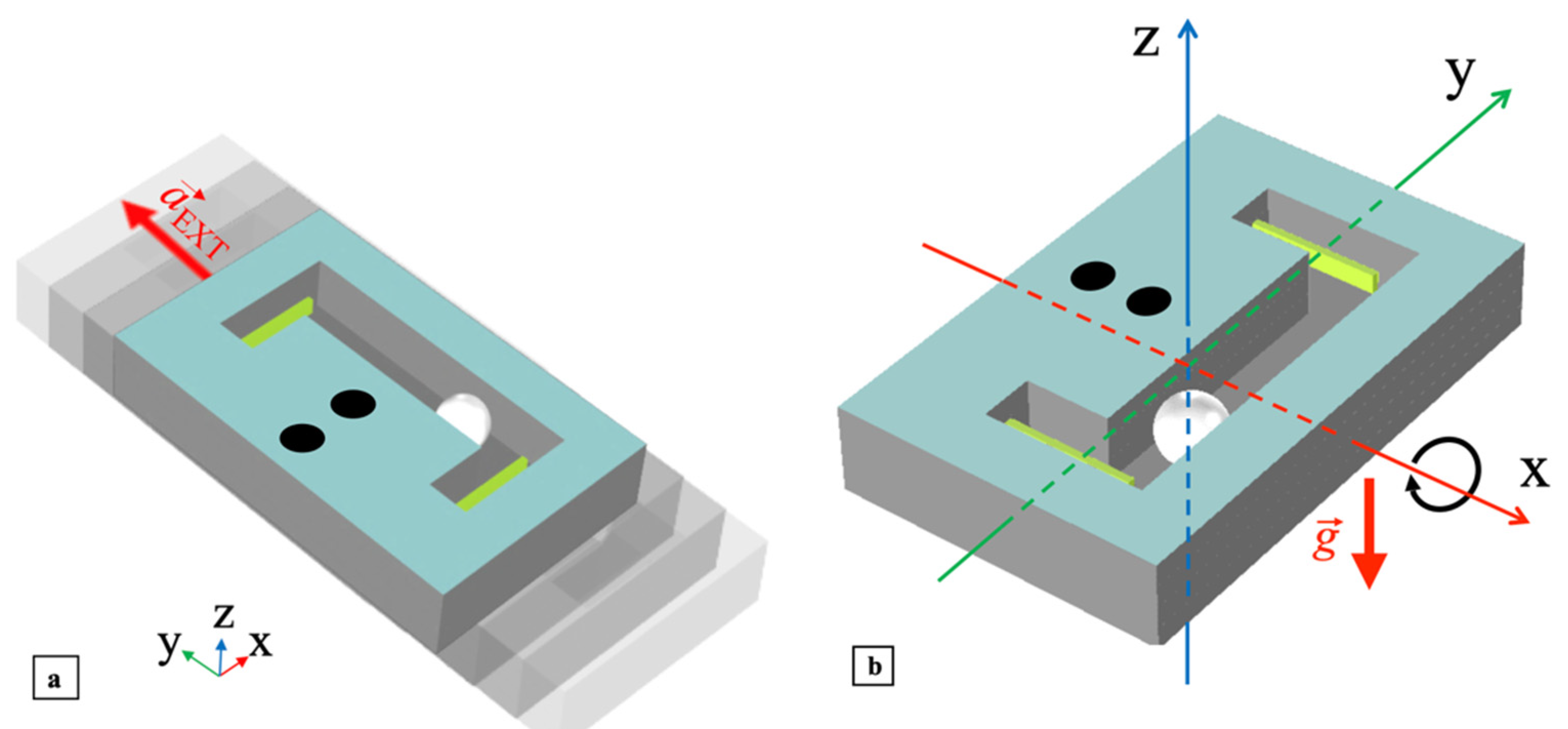
2. Mono-Axial and Bi-Axial Ball-Impact Multi-Converter Piezoelectric Harvester Description

The 3D structure of the mono-axial multi-converter piezoelectric harvester is illustrated in Figure 1a. The proposed device adopts two piezoelectric converters (PCs) impacted by a steel ball of diameter db to harvest electrical energy from mechanical energy. The path of the ball is confined within a predefined volume of a rectangular parallelepiped of height hpma ≅ 1.2db, width wpma ≅ 1.2db and length lpma ≅ 5.2db. The height hpma, width wpma and length lpma are defined by the top and bottom layers of the structure, the side walls of the structure and the position of the PCs, respectively.
To achieve mono-axial movements, the dimensions of the device were designed to make the axis along length lpma, denoted as the y-axis, the impacting axis. Within the delimited volume, the ball can freely move since it is not rigidly or elastically connected to the structure of the harvester.
Therefore, the ball will impact against a single PC when the harvester undergoes suitable external excitation causing the ball to roll and cover the corresponding distance to the PC. Two piezoceramic bimorph elements were employed as the PCs. Each PC is a rectangular parallelepiped of width wpc, length lpc and height hpc and was configured as a cantilever by mounting the face lpc × hpc in the xy-plane, as shown in Figure 1b.
The clamped end of the cantilever was placed at 1/5 of lpc, while the fraction of the length exposed to impacts is lpc0 ≅ 0.16lpc. In particular, wpma and lpc0 were selected to make the impact happen at the cantilever tips to maximize the induced free oscillations. The overall harvester structure is boxed in a rigid frame with width wma, length lma and height hma and includes electrical connections to the outputs of the embedded PCs. Assuming for reference that the harvester xy-plane is horizontal, two main different mechanical excitations can produce impacts with a PC, namely a shake applied along the y-axis or a tilt induced around the x-axis, as shown in Figure 2a,b, respectively, plus their combinations. In the first case, the external acceleration a ext produced by the shake, will directly cause the ball to impact one of the cantilevers. In the second case, the tilt around the x-axis will move the ball towards one of the cantilevers due to the action of the gravity acceleration g . The 3D structure of the bi-axial multi-converter piezoelectric harvester is illustrated in Figure 3a. The proposed bi-axial harvester exploits four PCs and a steel ball identical to the mono-axial harvester as the moving element. The path of the ball is confined within a predefined volume of a squared parallelepiped of height hpba ≅ 1.2db and width spba ≅ 2.3db.
The height is delimited by the top and bottom layers of the structure, while the sides are bounded by the four PCs. The parallelepiped dimensions were designed to make the x and y the impacting axes, therefore implementing a bi-axial ball-impact multi-converter piezoelectric harvester. As in the mono-axial harvester, the ball can move freely within the delimited volume since it is not rigidly or elastically connected to the structure. The ball will impact against a PC when the external excitation, applied to the harvester, causes the ball to move in either direction in the plane until it reaches one boundary.
In addition, subsequent impacts on different PCs can occur due to bouncing and angled deviation of the ball path. Four piezoceramic bimorph elements were employed as the PCs. As in the mono-axial harvester, the piezoelectric converters are rectangular parallelepipeds mounted as cantilevers with the face lpc × hpc oriented in the xy-plane, as shown in Figure 3b. The clamped end of each cantilever was placed at 1/5 of length lpc, while the length exposed to impacts is lpc0 ≅ 0.53lpc to keep the ball trajectory in the central region of the confined volume. The harvester structure was assembled in a rigid frame of length lba, composed of cylinder height hba, and diameter dba with electrical connections to the outputs of the embedded PCs and a hole for the mechanical support of external circuitry.
Assuming for reference that the harvester xy-plane is horizontal, four main different excitations can produce impacts on the PCs, namely a shake applied along the x- or y-axis, a tilt induced around the x- or y-axis, as shown in Figure 4a–d, respectively, plus their combinations. As in the mono-axial harvester, in the case of shake excitations, external acceleration a ext will cause the ball to impact the cantilevers, while for tilts gravity acceleration g will drive the impacts.

3. Analytical Modelling of a Transverse Ball Impact on a Cantilever Tip

The mechanical behavior of an impact happening between the ball and a single cantilever can be described by the simplified one-dimensional mechanical model and equivalent circuits shown in Figure 5. The model is composed of an elastic cantilever representing the piezoelectric converter impacted by a ball that moves towards its tip along the transverse y-axis, i.e., perpendicularly to the cantilever surface. According to the direct electro-mechanical (EM) analogy [51], the mechanical model can be analyzed by employing its equivalent electro-mechanical lumped-element circuit. The inductance, resistance, and capacitance represent in electrical formalism the equivalents of the mass, mechanical resistance, and elastic compliance, respectively. Specifically, the ball is modelled with a rigid mass mb, while the cantilever with an effective mass-spring-damper system, with equivalent mass meq, elastic compliance 1/keq and mechanical resistance Γeq, as shown in Figure 5a.
The ball impact on the cantilever is modeled considering three different time intervals named phases 1, 2 and 3 occurring before the impact, just after the impact, and after the ball detaches from the cantilever tip, respectively. The transitions among the three phases were modeled by the commutations of two ideal switches, assumed lossless and without a time delay.
Variables yc(t) and yb(t) represent the bending displacement of the cantilever tip and the displacement of the ball with respect to the cantilever equilibrium point yc = 0, respectively, while y ˙ c ( t ) and y ˙ b ( t ) denote the cantilever tip and ball velocities, respectively.
In phase 1, during the time interval before the impact, 0 ≤ t < ti, where ti is the time at which the impact occurs, neglecting the gravitational acceleration and considering the velocities as positive in the direction of the arrows, the ball is assumed in uniform rectilinear motion with constant velocity y ˙ b ( t ) = y ˙ b 0 , as shown in Figure 5b. In this case, since the ball and cantilever are not interacting yet, the switches in Figure 5a are in position 1 thus creating two equivalent lumped-element circuits which are separate and noninteracting. The mass mb and, according to the EM analogy, the equivalent inductance mb in turn, is considered to have an initial current condition y ˙ b ( 0 ) = y ˙ b 0 whereas the cantilever is supposed at rest at its equilibrium point, i.e., y ˙ c ( t ) and yc(t) = 0. Therefore, the capacitance 1/keq is initially uncharged and the initial current in the inductance meq is zero.
At time t = ti the ball impacts the tip of the cantilever which bends causing an inelastic collision [52]. In phase 2, during the time interval ti+ ≤ t < td, between the impact and detachment time td, the ball and the cantilever remain joined moving downwards with the same velocity, i.e., y ˙ b ( t ) = y ˙ c ( t ) = y ˙ b ( t i + ) , as shown in Figure 5c.
In this case a coupled system is created in which the overall spring constant and the mechanical resistance are those of the cantilever and the overall equivalent mass is the sum of the masses meq and mb. Accordingly, the switches in Figure 5a are in position 2 and, in the resulting equivalent circuit, the two inductors are in series. In this time interval, the ball and the cantilever tip initially move downwards until velocity y ˙ c ( t ) nulls and displacement yc reaches the negative maximum. Then the cantilever tip and the ball move upward until their maximum velocity, i.e., y ˙ b ( t d ) = y ˙ c ( t d ) = y ˙ b ( t d ) , is reached at yc = 0.
Once reached such condition, in phase 3 for t > td the ball detaches from the cantilever, as shown in Figure 5d. The ball leaves the cantilever with uniform rectilinear motion with velocity y ˙ b ( t ) = y ˙ b ( t d ) while the cantilever, due to its inertia, undergoes free oscillations until the mechanical damper dissipates all the energy transferred by the ball. The ball and cantilever return to behave as independent systems, the switches in Figure 5a are in position 3, coincident with position 1, and, correspondingly, the equivalent circuits are again uncoupled.
The second-order differential equation and initial conditions for the cantilever after the ball detachment for t > td are:
{ m eq y ¨ c ( t t d ) + Γ eq y ˙ c ( t t d ) + k eq y c ( t t d ) = 0 y ˙ c ( t d ) = y ˙ ( t d ) y c ( t d ) = 0 t > t d
The solution of Equation (1) is the displacement yc(t), resulting in:
y c ( t ) = y ˙ ( t d ) 2 π f dr sin ( 2 π f dr ( t - t d ) ) e - ( t - t d ) / τ ,
where fdr is the damped resonant frequency given by:
f dr = f r   2 - 1 ( 2 π τ ) 2
and
f r = 1 2 π k eq m eq ,
τ = 2 m eq Γ eq
are resonant frequency fr and decay time τ of the cantilever, respectively.
From Equation (2), the velocity of the cantilever tip y ˙ c (t) can be derived as follows:
y ˙ c ( t ) = [ - 1 τ   2 π f dr   sin ( 2 π f dr ( t - td ) ) + cos ( 2 π f dr ( t - td ) ) ] y ˙ ( t d ) e - ( t - t d ) / τ .
The typical behaviors of the velocity of the ball, y ˙ b ( t ) and of the cantilever tip y ˙ c ( t ) derived from the model and the resulting equations, are illustrated in Figure 6 with blue and red plots, respectively.

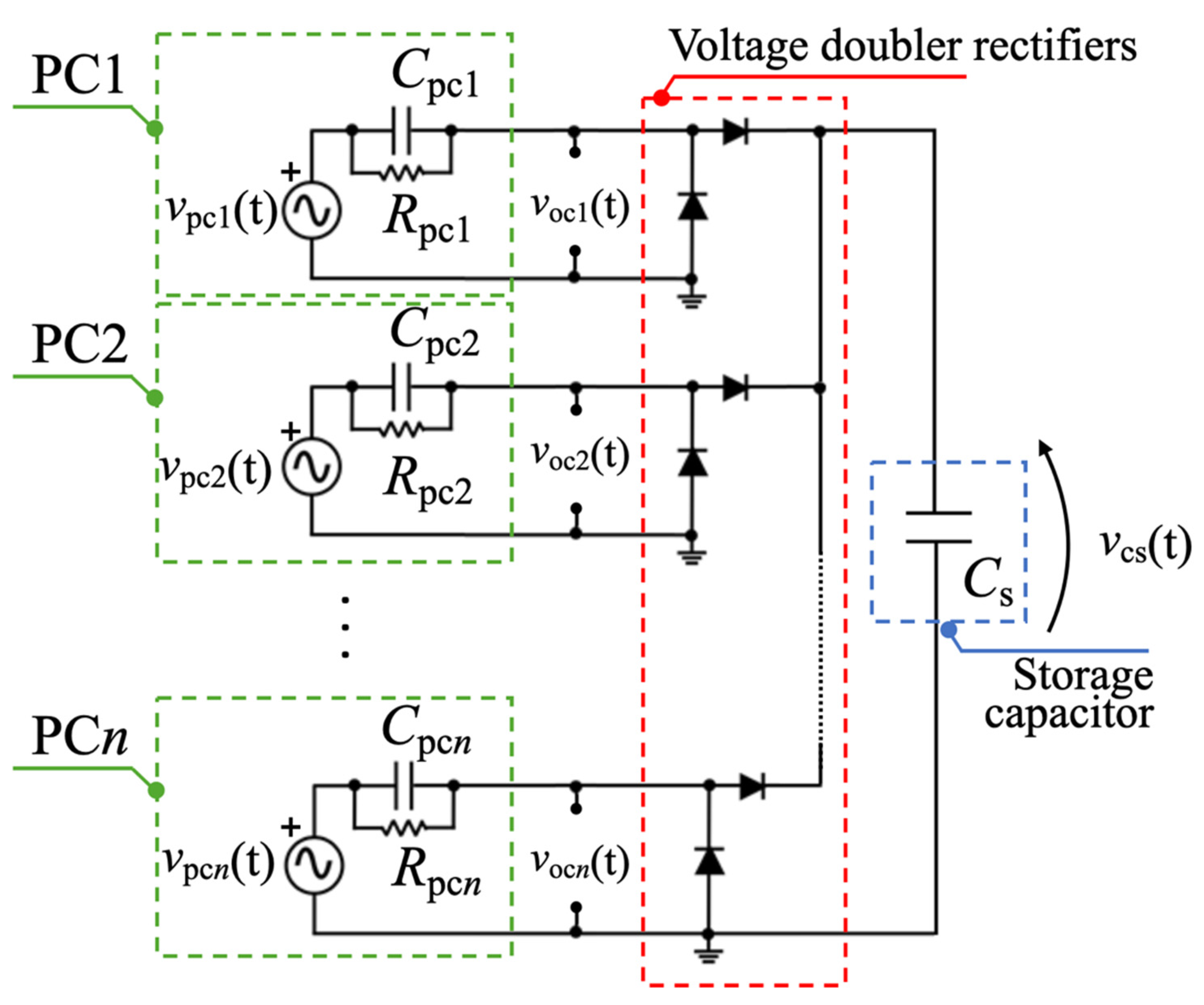
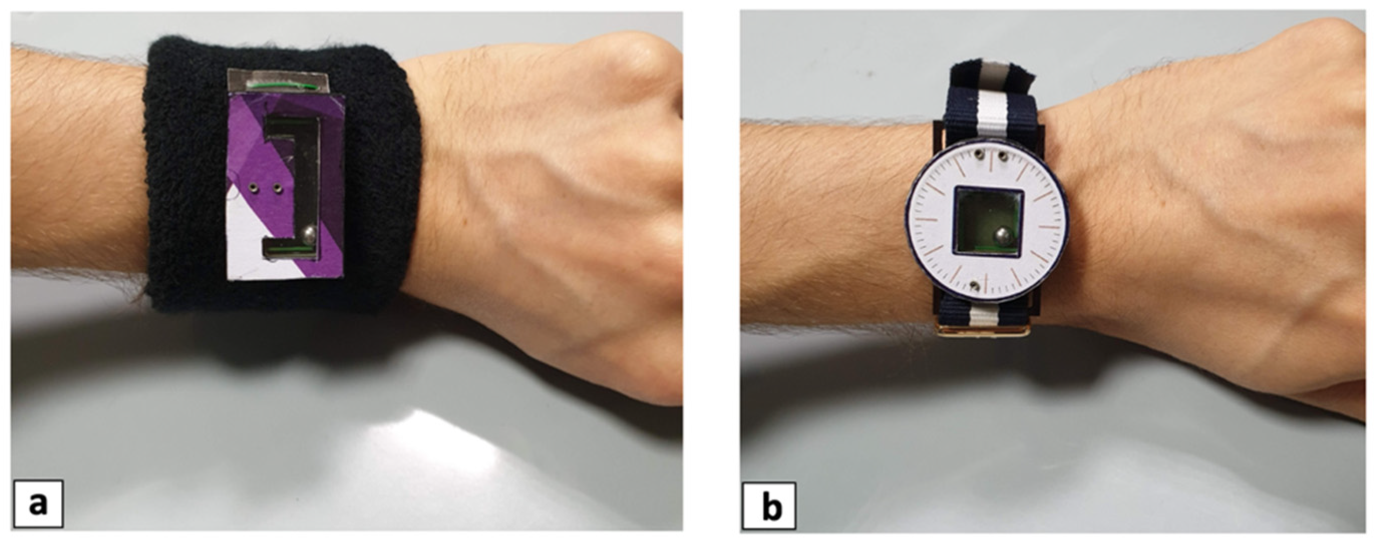
4. Prototypes and Electrical Configurations

Prototypes of the mono-axial and bi-axial ball-impact multi-converter harvesters described in Section 2 were fabricated employing 1.6 mm-thick FR-4 sheets as structural elements in a multi-layer arrangement.
Figure 7 shows the five processed FR-4 layers employed in the bi-axial harvester. A similar composite structure was developed for the mono-axial harvester. The bottom layer embeds the printed circuit board (PCB) and the rectifier circuits of each PC. The frame layer is placed on the bottom layer and is used to protect the electrical components and the PCB and to support the cantilever layer, where each PC was glued firmly into the clamped end. As per the piezoelectric converters, the three FR-4 layers, which compose the main structure of the harvester, have also been glued together with an epoxy resin.
To easily access the steel ball placed inside the harvester, a lid was built by employing a cover layer and a top layer glued together. Furthermore, a transparent plastic film and a paper stamp were glued on the top layer. The bi-axial harvester was embedded with three key pins, which provide mechanical support and correct alignment between the lid and structure body. Two of the three pins were also employed as electrical connections to electrically connect additional external circuitry to the harvester.
Images of the bi-axial harvester prototype are shown in Figure 8a, with views of the main structure and the bottom layer that compose the harvester. In particular, it is possible to notice the four piezoelectric converters, PC1–PC4, in the main structure, and the soldered electrical components in the bottom layer. Images of the mono-axial prototype are shown in Figure 8b with views of the main structure and the lid that compose the harvester. The two piezoelectric converters, PC1 and PC2, in the main structure and the electrical connections in the lid can be seen.
Commercial piezoceramic bimorph elements (RS-pro 285–784) were adopted as PCs capable of converting mechanical to electrical energy.
A single PC can be represented by its Thévenin equivalent circuit, comprising a voltage source, vpc(t), in series with the internal impedance of the piezoelectric element [53], made by the parallel of capacitance Cpc and resistance Rpc, as shown in Figure 9.
The electrical components Cpc and Rpc can be assumed to be frequency-independent, while vpc(t) determines open-circuit voltage voc(t) and reflects the dynamic mechanical response of the cantilever for each impact event, described in Section 3 and reported in Figure 6. Physical properties of the PCs and steel ball with the geometrical dimensions of the developed mono-axial and bi-axial harvesters are listed in Table 1. Piezoceramic elements can suffer possible long-term durability limitations after repeated impacts due to the intrinsic brittleness and sensitivity to the phenomenon of fatigue. The mass (0.51 g) and diameter (5 mm) of the ball were properly selected to keep mechanical properties compatible with wrist-worn applications and to prevent damage to the PCs. As a different approach, to further avoid overstress to PCs, solutions based on indirect impacts, e.g., impacts happening on the substrate on which the piezoelectric transducer is installed, or magnetic interactions to trigger the frequency-up conversion can be exploited [17,54].
To power the electronics within a sensor module, AC voltages vpcn(t), where n = 1, 2 for the mono-axial harvester and n = 1–4 for the bi-axial harvester, provided by each PCs had to be rectified [46,55]. Voltage-doubler rectifiers based on BAS116LP3-7 diodes were connected in parallel [56] to charge a single storage capacitor Cs, as reported in Figure 10. The voltage-doubler rectifiers were soldered on the bottom layer of each harvester while the storage capacitor was connected externally to the harvester through electrical connections. The proposed circuit was designed for PCs excited by discontinuous vibrations with an irregular intensity and repetition rate. To preserve the amount of charge extracted and stored in the capacitor Cs when no excitation is present, leakage currents were minimized for all selected components.

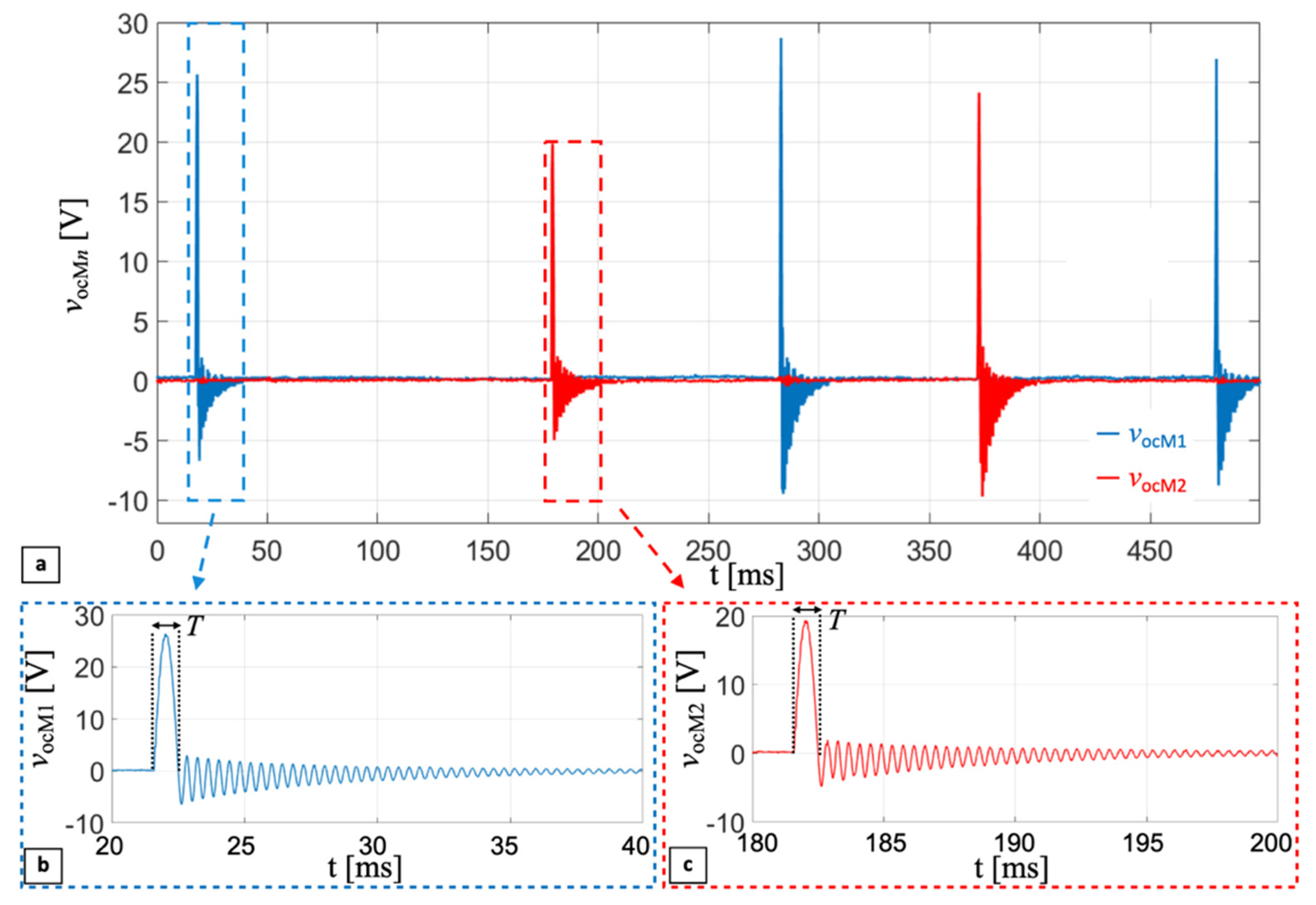
5. Experimental Results

The developed mono-axial and bi-axial prototypes were experimentally tested to validate the proposed ball-impact multi-converter mechanism and to estimate the performances in terms of measured open-circuit voltage and harvested electrical energy. The harvesters were provided with wristband and watchband to easily tie the prototypes to the wrist of a person, as illustrated in Figure 11a,b.
The open-circuit voltages, vocn(t), of the PCs that compose the harvesters were first acquired employing a MSOX3014A mixed signal oscilloscope, bypassing the diode-based voltage-doubler rectifiers. Taking into account the load effect of the input impedance of the oscilloscope, composed of the parallel of capacitor Cload = 14 pF and resistor Rload = 1 MΩ, the measured open-circuit voltage of n-PC vocMn(f) in the frequency domain results:
v ocMn ( f   ) = v ocn ( f   ) R pc R load   R pc + R load 1 + j 2 π f   R pc C pc 1 + j 2 π f   R pc R load   R pc + R load ( C pc + C load ) ,
Considering this, as reported in Table 1, Rload = Rpc, Equation (7) becomes:
v ocMn ( f   ) = v ocn ( f   ) 1 2 1 + j 2 π f   R pc C pc 1 + j 2 π f   R pc 2 ( C pc + C load ) .
Figure 12a reports the measured open-circuit voltages, vocM1(t) (blue curve), and vocM2(t) (red curve), of PC1 and PC2 for the mono-axial harvester, as a function of time, respectively. The five subsequent impacts were induced by rotations of the wrist, at an excitation rate of about 4 Hz. Figure 12b,c show enlarged images of a single impact happening on PC1 and PC2, respectively. The enlarged plots show an impact interval T of approximately half a cycle of a sine wave, whose peak value is related to the mass of the ball, the relative velocity between the cantilever and the ball at impact, and therefore to the excitation acceleration.
The following damped sinusoid is due to the cantilever undergoing free oscillations after the ball detachment, lasting until the mechanical damper dissipates all the energy transferred to the system by the ball, as described in Section 3. Frequency fdr of the damped sinusoidal oscillation is around 2.7 kHz. The reported experimental results show the frequency-up conversion of the impact technique. Low-frequency movements, induced by rotations of the wrist, thanks to the impact-based technique, make the PCs provide AC voltage at a frequency almost three orders of magnitude higher than the excitation frequency.
Considering the measured open-circuit voltages, vocMn(t), reported in Figure 12, and the trade-off between stored electric energy and charging time of a capacitor, an external storage capacitor Cs = 220 nF was connected to the electrical connections of the mono-axial harvester, including the diode-based voltage-doubler rectifiers, as described in Section 4. Voltage vcs(t) on the capacitor was acquired employing a Keithley 6517A electrometer used as a voltage buffer with an input impedance equivalent to capacitor Cel = 20 pF in parallel with a resistor Rel > 200 TΩ.
Figure 13 shows the vcs(t) (blue curve) produced by multiple consecutive impacts induced by repetitive wrist rotations. Energy Ecs stored in the capacitor, plotted as the red curve, was derived as follows:
E cs ( t ) = 1 2 C s v cs ( t ) 2 .
After 8.5 s of consecutive impacts, vcs(t) reached 40.2 V, which, from Equation (9), corresponds to a stored energy of 178 μJ.
To measure the electrical power provided by the bi-axial harvester, each PCs was directly connected to a resistor Ropt of 82 kΩ without the rectifier circuit. Such resistance value was chosen to match the magnitude of the cantilever impedance at the corresponding resonant frequency fr according to the data reported in Table 1. Voltages vRopt(t) of each Ropt connected to each PC were acquired for the bi-axial harvester. Figure 14 reports the measured voltages vRopt1(t) (blue curve), vRopt2(t) (yellow curve), vRopt3(t) (green curve) and vRopt4(t) (red curve), for PC1, PC2, PC3 and PC4, respectively, as a function of time. Three different impacts were induced on each PC by means of wrist rotations.
Based on the experimental results reported in Figure 14, considering the instantaneous power PRopt(t) from each PC, given by:
PRopt(t) = v2Ropt(t)/Ropt
Figure 15 shows the sum of the instantaneous powers from all PCs, PSRopt(t) (brown curve), and its average value (pink dotted line). The maximum peak value of PSRopt(t) is 1.58 mW while the average over 0.7 s results 9.65 μW. To evaluate the performances of the bi-axial harvester in terms of energy stored and charging time, two different values of storage capacitors Cs = 220 nF and Cs = 1 μF were tested. The external storage capacitor was connected to the electrical connections of the bi-axial harvester, including the diode-based voltage-doubler rectifier circuit, as described in Section 4. As per the mono-axial harvester, the voltage across the capacitor, vcs(t), was acquired employing the electrometer.
Figure 16 shows the measured rectified voltages, vcs(t) (blue curves), across the capacitor Cs produced by multiple consecutive impacts induced by repetitive rotations of the wrist. The corresponding electrical energies, Ecs, stored in the capacitor obtained from Equation (9) are also plotted (red curves).
To compare the effects that different values of storage capacitor Cs have on the charging process, the bi-axial harvester was subjected to consecutive controlled impacts until the voltage vcs(t) reached the preset threshold value of 6.2 V. Employing Cs = 220 nF, a charging time tc1 = 4.8 s was required to reach the threshold voltage, which was shorter than in the case with Cs = 1 μF where the charging time was tc2 = 7.6 s. However, for Cs = 220 nF the energy stored was almost one fourth of the energy stored with Cs = 1 μF. As expected, increasing the value of the storage capacitance at parity of threshold voltage increases both the stored energy and the charging time, which requires a trade-off in the selection of Cs.

6. Conclusions

In this work, mono-axial and bi-axial ball-impact piezoelectric harvesters are presented. The proposed harvesters exploit multiple piezoelectric converters (PCs) configured as cantilever to harvest electrical energy from mechanical energy employing a steel ball as a free-to-move element impacting the PCs.
The impact between the ball and the PCs happens as soon as the external excitation applied to the harvester by a shake or a tilt causes the ball to roll towards a cantilever. The path of the ball is confined within a predefined volume, designed to make the overall size compliant with the dimension constraints of wearable and unobtrusive devices.
A detailed description of the design of the harvesters is reported along with a basic electro-mechanical modeling of the impact between the ball and a single PC configured as a cantilever. Prototypes of the mono-axial and bi-axial ball-impact multi-converter harvesters were developed and experimentally tested by tying them to the wrist of a person by means of a wristband and watchband. Applying excitation frequencies of about 4 Hz by means of wrist rotations, the open-circuit voltages of the PCs of the mono-axial harvester and the voltages of the PCs connected to an optimal resistive load for the bi-axial harvester were measured. As theoretically predicted from the model, the measured trends exhibit a distinctive shape at impact, followed by a post-impact damped sinusoidal oscillation of around 2.7 kHz, which is related to the resonant frequency of the clamped unloaded cantilever.
The reported experimental results validate the frequency-up conversion of the impact technique. AC voltages with a frequency of almost three orders of magnitude higher than the excitation frequency were measured. The maximum peak value of the sum of the instantaneous powers for optimal resistive load resulted in 1.58 mW, while the average value over 0.7 s was 9.65 μW. The performances of the harvesters, in terms of stored energy and charging time, were evaluated connecting a storage capacitor, Cs = 220 nF, through the electrical terminals including passive diode-based rectifier circuits connected in parallel. After 8.5 s of consecutive impacts induced by wrist rotations, a voltage, vcs(t), of 40.2 V across Cs was obtained, which corresponds to a stored energy of 178 μJ. The proposed harvesters are suitable for sensor nodes where electrical energy has to be scavenged from low-frequency nonperiodical or random mechanical movements, such as human motion.
Ongoing activities are considering reliability and fatigue issues and are analyzing the effect of impacts occurring in different points of the harvester structure.

Author Contributions

Conceptualization, A.C. and V.F.; data curation, A.N. and N.P.; formal analysis, A.N., N.P. and M.B.; investigation, A.N. and M.F.; methodology, A.N., N.P., M.B. and P.A.; supervision, M.R., R.A., M.F., A.C. and V.F.; Validation, A.N. and N.P.; writing—original draft, A.N. and N.P.; writing—review and editing, A.N., M.B., P.A., M.R., R.A., M.F., A.C. and V.F. All authors have read and agreed to the published version of the manuscript.

Funding

The work was carried out under a collaborative project funded by the authoring institutions.

Informed Consent Statement

Informed consent was obtained from all subjects involved in the study.

Conflicts of Interest

The authors declare no conflict of interest.

References

  1. Grand View Research. Wearable Technology Market Size, Share & Trends Analysis Report by Product (Wrist-Wear, Eye-Wear & Head-Wear, Foot-Wear, Neck-Wear, Body-Wear), by Application, by Region, and Segment Forecasts, 2020–2027. 2020. Available online: https://www.grandviewresearch.com/industry-analysis/wearable-technology-market (accessed on 13 January 2022).
  2. Zhao, Y.; Wang, B.; Hojaiji, H.; Lin, S.; Lin, H.; Zhu, J.; Yeung, C.; Emaminejad, S. An Adhesive and Corrosion-Resistant Biomarker Sensing Film for Biosmart Wearable Consumer Electronics. JMEMS Lett. 2020, 29, 1112–1114. [Google Scholar] [CrossRef]
  3. Cascales, J.P.; Roussakis, E.; Witthauer, L.; Goss, A.; Li, X.; Chen, Y.; Marks, H.L.; Evans, C.L. Wearable device for remote monitoring of transcutaneous tissue oxygenation. Biomed. Opt. Express 2020, 11, 14. [Google Scholar] [CrossRef]
  4. Mazzaracchio, V.; Fiore, L.; Nappi, S.; Marrocco, G.; Arduini, F. Medium-distance affordable, flexible and wireless epidermal sensor for pH monitoring in sweat. Talanta 2021, 222, 10. [Google Scholar] [CrossRef] [PubMed]
  5. Haghi, M.; Thurow, K.; Stoll, R. Wearable Devices in Medical Internet of Things: Scientific Research and Commercially Available Devices. Healthc. Inform. Res. 2017, 23, 4–15. [Google Scholar] [CrossRef] [PubMed]
  6. Villani, V.; Righi, M.; Sabattini, L.; Secchi, C. Wearable Devices for the Assessment of Cognitive Effort for Human–Robot Interaction. IEEE Sens. J. 2020, 20, 13047–13056. [Google Scholar] [CrossRef]
  7. Tang, G.; Shi, Q.; Zhang, Z.; He, T.; Sun, Z.; Lee, C. Hybridized wearable patch as a multi-parameter and multi-functional human-machine interface. Nano Energy 2021, 81, 13. [Google Scholar] [CrossRef]
  8. Schiewe, A.; Krekhov, A.; Kerber, F.; Daiber, F.; Krüger, J. A Study on Real-Time Visualizations During Sports Activities on Smartwatches. In Proceedings of the 19th International Conference on Mobile and Ubiquitous Multimedia, Essen, Germany, 18–31 November 2020. [Google Scholar] [CrossRef]
  9. Trung, T.Q.; Lee, N.E. Flexible and stretchable physical sensor integrated platforms for wearable human-activity monitoring and personal healthcare. Adv. Mater. 2016, 28, 4338–4372. [Google Scholar] [CrossRef]
  10. Maharjan, P.; Toyabur, R.M.; Park, J.Y. A human locomotion inspired hybrid nanogenerator for wrist-wearable electronic device and sensor applications. Nano Energy 2018, 46, 383–395. [Google Scholar] [CrossRef]
  11. Gemelli, M.; Sakauchi, R.; Block, T.; Scheiermann, S. Low cost MEMS based systems augmenting location and navigation performance in consumer and industrial electronics applications. In Proceedings of the 2020 IEEE/ION Position, Location and Navigation Symposium (PLANS), Portland, OR, USA, 20–23 April 2020; pp. 1439–1443. [Google Scholar] [CrossRef]
  12. Zhang, L.; Liu, D.; Wub, Z.S.; Lei, W. Micro-supercapacitors powered integrated system for flexible electronics Energy. Storage Mater. 2020, 32, 402–417. [Google Scholar] [CrossRef]
  13. Xiwei, M.; He, Z.; Wenbo, L.; Zisheng, X.; Jiangjiang, D.; Liang, H.; Bin, H.; Jun, Z. Piezoelectrets for wearable energy harvesters and sensors. Nano Energy 2019, 65, 22. [Google Scholar] [CrossRef]
  14. Srivastava, G.; Dixit, A.; Kumar, A.; Shukla, S. Review of Ultra-Low-Power CMOS Amplifier for Bio-electronic. Adv. Intell. Syst. Comput. 2021, 1168, 432–443. [Google Scholar] [CrossRef]
  15. Ram, S.K.; Das, B.B.; Pati, B.; Panigrahi, C.; Mahapatra, K.K. SEHS: Solar Energy Harvesting System for IoT Edge Node Devices Progress. Adv. Intell. Syst. Comput. 2021, 1199, 432–443. [Google Scholar] [CrossRef]
  16. Pellegrinelli, G.; Baù, M.; Cerini, F.; Dalola, S.; Ferrari, M.; Ferrari, V. Portable Energy-Logger Circuit for the Experimental Evaluation of Energy Harvesting Solutions from Motion for Wearable Autonomous Sensors. In Proceedings of the Eurosensors 2014, Brescia, Italy, 7–10 September 2014; Volume 87, pp. 1230–1233. [Google Scholar] [CrossRef] [Green Version]
  17. Ferrari, M.; Baù, M.; Cerini, F.; Ferrari, V. Impact-Enhanced Multi-Beam Piezoelectric Converter for Energy Harvesting in Autonomous Sensors. In Proceedings of the Eurosensors 2012, Krakow, Poland, 9–12 September 2012; pp. 418–421. [Google Scholar] [CrossRef] [Green Version]
  18. Ferrari, M.; Ferrari, V.; Guizzetti, M.; Marioli, D. An autonomous battery-less sensor module powered by piezoelectric energy harvesting with RF transmission of multiple measurement signals. Smart Mater. Struct. 2009, 18, 9. [Google Scholar] [CrossRef]
  19. Erturun, U.; Eisape, A.; West, J.E. Design and analysis of a vibration energy harvester using push-pull electrostatic conversion. Smart Mater. Struct. 2020, 29, 12. [Google Scholar] [CrossRef]
  20. Tao, Z.; Wu, H.; Li, H.; Li, H.; Xu, T.; Sun, J.; Wang, W. Theoretical model and analysis of an electromagnetic vibration energy harvester with nonlinear damping and stiffness based on 3D MEMS coils. J. Phys. D Appl. Phys. 2020, 53, 12. [Google Scholar] [CrossRef]
  21. Zhu, D.; Evans, L. Numerical analysis of an electromagnetic energy harvester driven by multiple magnetic forces under pulse excitation. Smart Mater. Struct. 2018, 27, 13. [Google Scholar] [CrossRef]
  22. Hall, R.G.; Rashidi, R. Multi-Directional Universal Energy Harvesting Ball. Micromachines 2021, 12, 457. [Google Scholar] [CrossRef]
  23. Pan, H.Y.; Qi, L.F.; Zhang, X.T.; Zhang, Z.T.; Salman, W.; Yuan, Y.P.; Wang, C.B. A portable renewable solar energy-powered cooling system based on wireless power transfer for a vehicle cabin. Appl. Energy 2017, 195, 334–343. [Google Scholar] [CrossRef]
  24. Wang, Z.L.; Chen, J.; Lin, L. Progress in triboelectric nanogenerators as a new energy technology and self-powered sensors. Energy Environ. Sci. 2015, 8, 2250–2282. [Google Scholar] [CrossRef]
  25. Bowen, C.R.; Taylor, J.; Leboulbar, E.; Zabek, D.; Chauhan, A.; Vaish, R. Pyroelectric materials and devices for energy harvesting applications. Energy Environ. Sci. 2014, 7, 3836–3856. [Google Scholar] [CrossRef] [Green Version]
  26. Tang, M.; Guan, Q.; Wu, X.; Zeng, X.; Zhang, Z.; Yuan, Y. A high-efficiency multidirectional wind energy harvester based on impact effect for self-powered wireless sensors in the grid. Smart Mater. Struct. 2019, 28, 13. [Google Scholar] [CrossRef]
  27. Gafforelli, G.; Ardito, R.; Corigliano, A. Improved one-dimensional model of piezoelectric laminates for energy harvesters including three-dimensional effects. Compos. Struct. 2015, 127, 369–381. [Google Scholar] [CrossRef] [Green Version]
  28. Ardito, R.; Corigliano, A.; Gafforelli, G.; Valzasina, C.; Procopio, F.; Zafalon, R. Advanced model for fast assessment of piezoelectric micro energy harvesters. Front. Mater. 2016, 3, 9. [Google Scholar] [CrossRef] [Green Version]
  29. Maamera, B.; Boughamourac, A.; Fath El-Babd, A.M.R.; Francise, L.A.; Tounsi, F. A review on design improvements and techniques for mechanical energy harvesting using piezoelectric and electromagnetic schemes. Energy Convers. Manag. 2019, 199, 23. [Google Scholar] [CrossRef]
  30. Procopio, F.; Valsazina, C.; Corigliano, A.; Ardito, R.; Gafforelli, G. Piezoelectric Transducer for an Energy-Harvesting System. U.S. Patent US20150035409 A1, 5 February 2015. [Google Scholar]
  31. Yu, X.; Liang, X.; Krishnamoorthy, R.; Jiang, W.; Zhang, L.; Ma, L.; Zhu, P.; Hu, Y.; Sun, R.; Wong, C.P. Transparent and flexible hybrid nanogenerator with welded silver nanowire networks as the electrodes for mechanical energy harvesting and physiological signal monitoring. Smart Mater. Struct. 2020, 29, 11. [Google Scholar] [CrossRef]
  32. Lee, M.; Chen, C.Y.; Wang, S.; Cha, S.N.; Park, Y.J.; Kim, J.M.; Chou, L.J.; Wang, Z.L. A hybrid piezoelectric structure for wearable nanogenerators. Adv. Mater. 2012, 24, 1759–1764. [Google Scholar] [CrossRef] [PubMed]
  33. Baù, M.; Alghisi, D.; Dalola, S.; Ferrari, M.; Ferrari, V. Multi-frequency array of nonlinear piezoelectric converters for vibration energy harvesting. Smart Mater. Struct. 2020, 29, 085047. [Google Scholar] [CrossRef]
  34. Cai, M.; Liao, W.H. Enhanced electromagnetic wrist-worn energy harvester using repulsive magnetic spring. Mech. Syst. Signal Process. 2021, 150, 17. [Google Scholar] [CrossRef]
  35. Xiao, H.; Wang, X. A review of piezoelectric vibration energy harvesting techniques. Int. Rev. Mech. Eng. 2014, 8, 609–620. [Google Scholar]
  36. Yang, G.; Tian, M.Z.; Huang, P.; Fu, Y.F.; Li, Y.Q.; Fu, Y.Q.; Wang, X.Q.; Li, Y.; Hu, N.; Fu, S.Y. Flexible pressure sensor with a tunable pressure-detecting range for various human motions. Carbon 2021, 173, 736–743. [Google Scholar] [CrossRef]
  37. Mitcheson, P.D.; Green, T.C.; Yeatman, E.M.; Holmes, A.S. Architectures for Vibration-Driven Micropower Generators. J. Microelectromech. Syst. 2004, 13, 429–440. [Google Scholar] [CrossRef] [Green Version]
  38. Yang, J.; Yin, L.; Tan, J.; Zhao, Z.; Wang, G. Transition mechanism and dynamic behaviors of a multi-stable piezoelectric energy harvester with magnetic interaction. J. Sound Vib. 2021, 501, 116074. [Google Scholar] [CrossRef]
  39. Cai, M.; Liao, W.H. High Power Density Inertial Energy Harvester Without Additional Proof Mass for Wearables. IEEE Internet Things J. 2020, 8, 297–308. [Google Scholar] [CrossRef]
  40. Karimpour, H.; Eftekhari, M. Exploiting double jumping phenomenon for broadening bandwidth of an energy harvesting device. Mech. Syst. Signal Process. 2020, 139, 18. [Google Scholar] [CrossRef]
  41. Gafforelli, G.; Xu, R.; Corigliano, A.; Kim, S.G. Experimental verification of a bridge-shaped, nonlinear vibration energy harvester. Appl. Phys. Lett. 2014, 105, 203901. [Google Scholar] [CrossRef] [Green Version]
  42. Gafforelli, G.; Xu, R.; Corigliano, A.; Kim, S.G. Modelling of a bridge-shaped nonlinear piezoelectric energy harvester. J. Phys. Conf. Ser. 2014, 476, 179–187. [Google Scholar] [CrossRef] [Green Version]
  43. Rui, X.; Zhang, Y.; Zeng, Z.; Yue, G.; Huang, X.; Li, J. Design and analysis of a broadband three-beam impact piezoelectric energy harvester for low-frequency rotational motion. Mech. Syst. Signal Process. 2021, 149, 107307. [Google Scholar] [CrossRef]
  44. Speciale, A.; Ardito, R.; Baù, M.; Ferrari, M.; Ferrari, V.; Frangi, A. Snap-through buckling mechanism for frequency-up conversion in piezoelectric energy harvesting. Appl. Sci. 2020, 10, 3614. [Google Scholar] [CrossRef]
  45. He, X.; Siong, K.; Li, S.; Dong, L.; Jiang, S. Modeling and experimental verification of an impact-based piezoelectric vibration energy harvester with a rolling proof mass. Sens. Actuators A 2017, 259, 171–179. [Google Scholar] [CrossRef]
  46. Alghisi, D.; Dalola, S.; Ferrari, M.; Ferrari, V. Triaxial ball-impact piezoelectric converter for autonomous sensors exploiting energy harvesting from vibrations and human motion. Sens. Actuators A 2015, 233, 569–581. [Google Scholar] [CrossRef]
  47. Yi, Z.; Yang, B.; Zhang, W.; Wu, Y.; Liu, J. Batteryless Tire Pressure Real-Time Monitoring System Driven by an Ultralow Frequency Piezoelectric Rotational Energy Harvester. IEEE Trans. Ind. Electron. 2021, 68, 3192–3201. [Google Scholar] [CrossRef]
  48. Fang, S.; Wang, S.; Zhou, S.; Yang, Z.; Liao, W.H. Exploiting the advantages of the centrifugal softening effect in rotational impact energy harvesting. Appl. Phys. Lett. 2020, 116, 063903. [Google Scholar] [CrossRef]
  49. Van Minh, L.; Hara, M.; Oguchi, H.; Kuwano, H. Lead-free (K, Na)NbO3 based impact type energy harvesters integrated with a cylindrical cavity for metal ball. In Proceedings of the IEEE 26th International Conference on Micro Electro Mechanical Systems (MEMS), Taipei, Taiwan, 20–24 January 2013; pp. 833–836. [Google Scholar]
  50. Fan, G.; Wang, Y.; Tian, F.; Hao, M.; Wen, Y.; Xu, Y.; Zeng, F.; Lu, W. Impact-driven piezoelectric energy harvester using a pendulum structure for low-frequency vibration. J. Intell. Mater. Syst. Struct. 2021, 32, 1997–2005. [Google Scholar] [CrossRef]
  51. Ferrari, V. Measuring instrumentation. In Applied Structural and Mechanical Vibrations: Theory, Methods and Measuring Instrumentation; Gatti, P.L., Ferrari, V., Eds.; E&FN SPON Taylor & Francis Group: London, UK, 1999. [Google Scholar]
  52. Umeda, M.; Nakamura, K.; Ueha, S. Analysis of the transformation of mechanical impact energy to electric energy using piezoelectric vibrator. Jpn. J. Appl. Phys. 1996, 35, 1347–4065. [Google Scholar] [CrossRef]
  53. Kim, J.E. Dedicated algorithm and software for the integrated analysis of AC and DC electrical outputs of piezoelectric vibration energy harvesters. J. Mech. Sci. Technol. 2014, 28, 4027–4036. [Google Scholar] [CrossRef]
  54. Rosso, M.; Corigliano, A.; Ardito, R. An investigation on the magnetic interaction for frequency up-converting piezoelectric vibration energy harvesters. In Proceedings of the 2021 IEEE 20th International Conference on Micro and Nanotechnology for Power Generation and Energy Conversion Applications (PowerMEMS), Exeter, UK, 6–8 December 2021; pp. 232–235. [Google Scholar]
  55. Avant, T.; Cruce, J.; Park, G.; Farinholt, K. Evaluation of energy harvesting conditioning circuits. Proc. SPIE 2012, 83430A. [Google Scholar] [CrossRef]
  56. Ferrari, M.; Ferrari, V.; Guizzetti, M.; Marioli, D. Investigation on electrical output combination options in a piezoelectric multifrequency converter array for energy harvesting in autonomous sensors. In Proceedings of the Sensor Devices 2010, Venice, Italy, 18–25 July 2010; pp. 258–263. [Google Scholar] [CrossRef]
Figure 1. A 3D view (a) and top view (b) of the mono-axial multi-converter piezoelectric harvester.
Sensors 22 00772 g001
Figure 2. Excitations to which the mono-axial harvester is sensitive: shake applied along the y-axis (a) and tilt around the x-axis (b).
Sensors 22 00772 g002
Figure 3. 3D view (a) and top view (b) of the bi-axial multi-converter piezoelectric harvester.
Sensors 22 00772 g003
Figure 4. Excitations to which the bi-axial harvester is sensitive: shake applied along the x- (a) and y-axis (b) and tilt around the x- (c) and y-axis (d).
Sensors 22 00772 g004
Figure 5. Lumped-element equivalent circuits (a) and equivalent simplified mechanical model of a single ball impact piezoelectric converter before the impact (b), after the impact (c), and after the detachment of the ball from the cantilever (d).
Sensors 22 00772 g005
Figure 6. Typical behaviors of the velocity of the ball, y ˙ b ( t ) (blue curve), and of the cantilever tip, y ˙ c ( t ) (red curve), caused by an impact.
Sensors 22 00772 g006
Figure 7. Images of the FR-4 layers that compose the main structure and the lid of the fabricated bi-axial multi-converter harvester prototype.
Sensors 22 00772 g007
Figure 8. Images of the mono-axial (a) and bi-axial (b) multi-converter harvester prototypes with views of the main structures, bottom layer, and lid.
Sensors 22 00772 g008
Figure 9. Thévenin equivalent model of a single PC.
Sensors 22 00772 g009
Figure 10. Passive parallel-like electrical configuration of a generic n-multi-converter piezoelectric harvester.
Sensors 22 00772 g010
Figure 11. Images of the wearable mono-axial (a) and bi-axial (b) multi-converter harvester prototypes.
Sensors 22 00772 g011
Figure 12. Measured open-circuit voltages, vocMn(t), of piezoelectric converter PC1 (blue curve) and PC2 (red curve) of the mono-axial harvester (a). Enlarged images of a single impact happening against PC1 (b) and PC2 (c).
Sensors 22 00772 g012
Figure 13. Measured rectified voltage vcs(t) (blue curve) and estimated energy Ecs (red curve) stored in capacitor Cs, induced by multiple consecutive impacts.
Sensors 22 00772 g013
Figure 14. Measured voltages vRopt(t) as a function of time with three different impacts happening against each PCs of the bi-axial harvester PC1, PC2, PC3, and PC4, reported with blue, yellow, green, and red curves, respectively.
Sensors 22 00772 g014
Figure 15. Sum of the instantaneous power PSRopt(t) (brown curve) and its average value (pink dotted line), obtained from the experimental results reported in Figure 14.
Sensors 22 00772 g015
Figure 16. Measured rectified voltage vcs(t) (blue curves) and estimated electrical energy Ecs(t) (red curves) stored employing two different values of storage capacitors Cs.
Sensors 22 00772 g016
Table 1. Physical properties of the employed PCs and steel ball and geometrical dimensions of the developed mono-axial and bi-axial harvesters.
DescriptionParameterValue
Piezoelectric Converter (PC)
widthwpc1.5 mm
heighthpc0.6 mm
lengthlpc15 mm
capacitanceCpc750 ± 170 pF
resistanceRpc1 MΩ
Steel Ball
diameterdb5 mm
massmb0.51 g
Mono-Axial Harvester
lengthlma40 mm
widthwma25.5 mm
heighthma8 mm
parallelepiped lengthlpma25.8 mm
parallelepiped widthwpma6 mm
parallelepiped heighthpma6.4 mm
PC length exposed to impactlpc02.5 mm
Bi-Axial Harvester
lengthlba44 mm
heighthba8 mm
diameterdba36 mm
parallelepiped sidespba11.6 mm
parallelepiped heighthpba6.4 mm
PC length exposed to impactlpc08.05 mm
Publisher’s Note: MDPI stays neutral with regard to jurisdictional claims in published maps and institutional affiliations.

