Abstract
We report an ytterbium (Yb) doped fiber Mach Zehnder interferometer (MZI) based on the up-taper fiber structure in a fiber ring laser (FRL) cavity. Different from the traditional FRL sensing system, in which additional filters are required, the designed structure simultaneously acts as a filter, sensor and gain medium. Furthermore, thanks to the high thermal–optical coefficient of Yb doped fiber, the temperature sensitivity of 0.261 nm/°C can be achieved in the range of 10–50 °C. In addition, benefiting from the unique characteristics of the laser system itself, the designed structure has a narrower linewidth (−0.2 nm) and a higher signal-to-noise ratio (SNR) (−40 dB) than the sensor system based on a broadband light source (BBS). Meanwhile, the refractive index (RI) response and stability of the system are measured. The RI sensitivity is up to 151 nm/RIU, and the wavelength fluctuation range within two hours is less than 0.2 nm. Therefore, the designed structure is expected to play a significant role in human life safety monitoring, aircraft engine temperature monitoring, etc.
1. Introduction
In recent years, optical fiber sensing technology has received extensive attention [1,2,3,4] because of its small size, light weight, low price and high sensitivity [5,6,7]. Its application range includes electromagnetic field detection [8,9,10,11], tumor marker measurement [12,13,14], and temperature or RI calibration [15,16,17,18,19,20], etc. Among them, optical fiber temperature and RI sensors have been widely reported because of immunity to electromagnetic interference and multiplexing capabilities [21,22,23,24]. However, the traditional optical fiber sensor uses a BBS as the light source [25,26,27], resulting in poor spectral quality and generate many burrs, which affects the accuracy and stability of the measurement.
An FRL cavity is gradually regarded as a substitute for the BBS because of its high SNR and narrow linewidth [28,29,30]. The interference structure is usually designed in the cavity as the filter unit. When the disturbance occurs in an external environment, the central wavelength of the system will shift. Liu et al. designed an RI sensor based on coreless fiber [31] and systematically studied the effects of wavelength and pulse width on the sensor property. The results demonstrate that the function of the sensing structure intensely depends on the interrogation wavelength, and the narrower pulse width helps to avoid the interference of relaxation oscillation. The detection sensitivity of −3271 µs/RIU is obtained. However, the designed structure requires photoelectric detectors and oscilloscopes to perform photoelectric conversion, which reduces the system efficiency. Mateusz et al. realized the simultaneous measurement of humidity and temperature by using a cascaded fiber Bragg grating (FBG) [32]. However, due to the inherent properties of the FBG, the detection sensitivity obtained is particularly low. In 2016, Zhao et al. made pioneering use of an up-taper MZI to measure temperature and RI in an FRL system, greatly improving the detection limit and SNR [33].
Here, we propose an MZI based on the up-taper structure of Yb doped fiber. In the FRL system, the cladding mode is excited by the first sphere and then recoupled in the second sphere after transmission to obtain interference. It benefits from the strong thermal–optical coefficient of rare earth optical fiber, and a temperature sensitivity of 0.261 nm/°C in the range of 10–50 °C was achieved. Furthermore, the RI response characteristics of the designed MZI was studied. It was found that the RI monitoring with sensitivity up to 144 pm/RIU could be realized. At the same time, the variation range of wavelength and intensity within 2 h is less than 0.2 nm and 0.5 dB, respectively, which verifies the practicability of the sensor. Benefiting from the inherent properties of the FRL, the linewidth of the designed structure is less than 0.2 nm, and the SNR is up to 40 dB. The sensor structure designed is expected to play a potential role in life health monitoring and stable operation of spacecraft.
2. Sensor Setup and Principle
The designed interferometer sensor structure is shown in Figure 1. MZI is composed of two cascaded Yb doped fiber up-taper structures. The output light is transmitted to the first spherical structure through the first section of Yb doped fiber. Firstly, the optical energy is transmitted in the fiber core in the modality of core mode. When the light transmission gets past the first sphere, the cladding mode is excited because of the mismatch of core diameter; when the core mode and cladding mode reach the second sphere, some higher-order cladding modes will recouple and then propagate along the fiber core. Since different modes have different phases, the interference between modes will occur.

Figure 1.
Schematic diagram of up-taper structure on Yb doped fiber.
The light intensity expression of the output interference spectrum can be expressed as:
in which is the light intensity of core mode and is the light intensity of higher-order cladding mode. Because of diverse propagation constants among different modes, after the same transmission distance, there will exist phase difference between different modes. The higher-order cladding modes excited in the up-taper-structure-based MZI partake in the interference. The cladding modes of different orders are related to different effective RI, and the phase difference between the core mode and the n-step cladding mode can be expressed as:
where is the output light wavelength, is the effective RI of core mode, is the effective RI of different high order cladding mode, and is the effective length of interference arm. The free spectral range of the interference spectrum can be expressed as:
When the external temperature and refractive index change, the interference spectrum will shift. The expressions can be expressed as:
in which and are the thermal–optical coefficient and thermal-expansion coefficient of the optical fiber, respectively. Since Yb doped fiber has higher thermal–optical coefficient than erbium doped fiber and single-mode fiber, higher temperature sensitivity can be achieved. is the external RI value and is the difference between cladding modes and core mode.
The microstructure of the up-taper shape is shown in Figure 2. The structure can be easily fabricated by an optical fiber fusion splicer (Fujikura 80C, Japan). Firstly, we used the fiber cutter to smooth the end face of Yb doped fiber. Then, one end of the optical fiber was placed in the fusion splicer, discharging twice using parameters of +100 bit discharge power and 15,000 ms discharge time to form a smooth 325 μm spherical structure. The above operation was repeated to make another sphere. Finally, the two spheres were welded by a 1.5 cm Yb doped fiber to form the required structure after adjusting the welding mode to single mode welding mode.
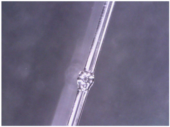
Figure 2.
Micrograph of up-taper structure on Yb doped fiber.
In order to verify whether the designed up-taper structure can produce the interference phenomenon, a BBS (Anyang SC-5) is used to connect the structure directly, and an optical spectrum analyzer (OSA, Yokogawa AQ6370D) is used to detect the wavelength movement, as shown in Figure 3.
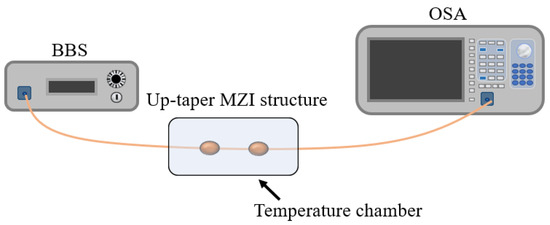
Figure 3.
Experimental setup of Yb doped fiber up-tapered structure.
Furthermore, we used the FRL cavity for sensing experiments. Unlike traditional FRL systems, as shown in Figure 4, additional filters need to be designed for sensing monitoring. Yb doped fiber MZI can be used as filter, sensor and gain medium simultaneously. Without additional filtering structure, the system structure is simplified and the structure stability is increased.

Figure 4.
Traditional FRL sensing structure logic framework.
The designed sensing structure is shown in Figure 5. The 980 nm pump source (PL-974-500-FC/APC-P-M) enters the ring cavity through the wavelength division multiplexer (WDM), gains the Yb doped fiber, and the tail end of the Yb doped fiber is designed into up-taper MZI structures through the fiber fusion splicer to produce interference effects. When the temperature changes, the corresponding interference spectrum will shift. An isolator is used to prevent optical reverse transmission from damaging devices. The modulated light passes through the 90:10 coupler and outputs 10% of the laser intensity to the OSA for monitoring. The remaining light intensity continues to circulate in the cavity. Based on this structure, we successfully monitored the temperature and RI characteristics of an Yb doped fiber MZI structure.
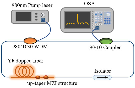
Figure 5.
The intracavity sensing system of the FRL without extra sensing head.
3. Results
Figure 6 shows the rule of spectrum change with temperature under BBS as shown in the pre-experiment. In the range of 10–50 °C, the wavelength moves to short wavelength as the temperature rises.
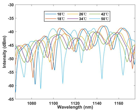
Figure 6.
Wavelength versus temperature curve under BBS.
Figure 7 shows the linear fitting curve of wavelength with temperature when the measurement interval is 8 °C. The test sensitivity is as high as 0.314 nm/°C according to the figure. Meanwhile, the linear regression coefficient is 0.989. The linearity and feasibility of the sensor are proved. In addition, error bars are also provided, and it can be found that the error value of multiple measurements is less than 0.2 nm.
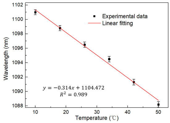
Figure 7.
Linear regression curve of temperature with wavelength at BBS.
Figure 8 shows the relationship between the output laser wavelength and the output result by using a BBS. It can be noted that the laser output is at the peak of the interference spectrum. This proves the accuracy of MZI working as a laser cavity filter. At the same time, the burr on the spectral edge may be caused by the unstable operation of the isolator.
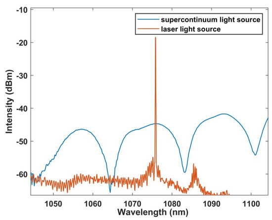
Figure 8.
Corresponding curve of the output laser spectrum and interference spectrum.
Figure 9 and Figure 10 show the relationship between the laser spectral shift and temperature in the FRL system. It can be found that the laser has a significant blue shift as the temperature increases. Good linearity can be obtained by testing every 4 °C in the range of 10–50 °C. The temperature sensitivity is 0.261 nm/°C, which is slightly lower than that of the BBS, possibly due to the deviation between the selected interference wave trough and the laser output. However, the laser still maintains good linearity with R squared up to 0.999 and error bar less than 0.15 nm, which proves the stability and consistency of the system.
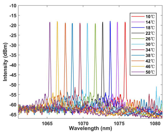
Figure 9.
Wavelength versus temperature curve at FRL.
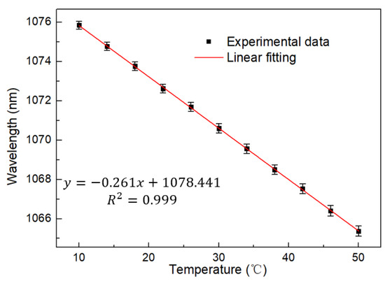
Figure 10.
Linear regression curve of temperature with wavelength at FRL.
In addition, the RI response characteristics of the designed MZI structure are analyzed. The results are shown in Figure 11 and Figure 12. Within the RI range of 1.3335–1.3555, the wavelength moves to shorter wavelength, and the corresponding response sensitivity is −144.758 nm/RIU, with a linear fit up to 0.992.
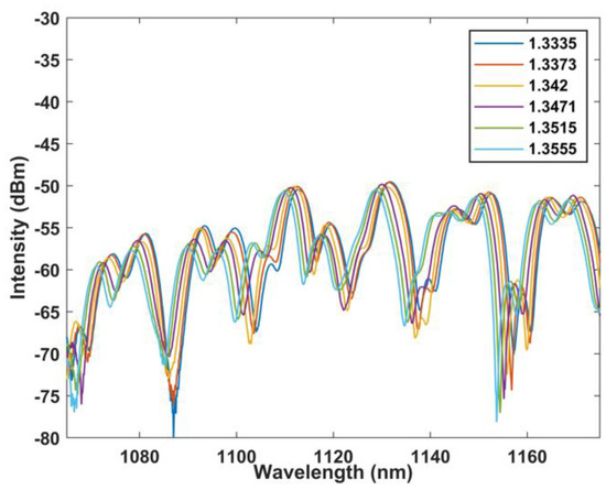
Figure 11.
Wavelength versus RI curve at BBS.
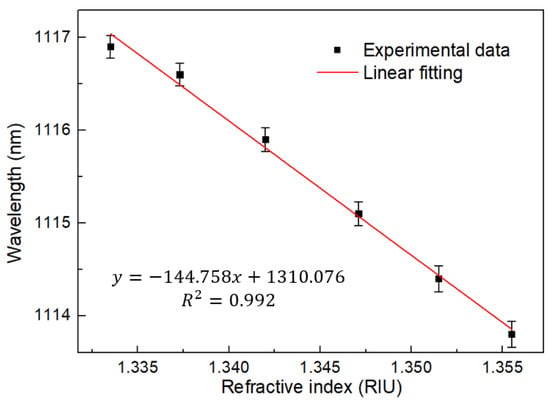
Figure 12.
Linear regression curve of RI with wavelength at BBS.
The response characteristics of the laser light source are shown in Figure 13 and Figure 14, and its sensitivity is −151.739 nm/RIU with the linearity of 0.997. For the RI, we repeated the experiment for five times, and the error bar obtained is less than 0.13 nm. Therefore, it can be considered that the sensor has good repeatability. It must be discussed that the burr on the laser edge may be caused by the selected isolator being a polarization maintaining isolator.
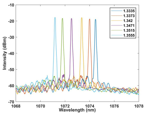
Figure 13.
Wavelength versus RI curve at FRL.
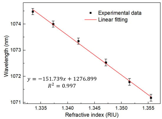
Figure 14.
Linear regression curve of RI with wavelength at FRL.
Finally, we tested the laser stability at 10 °C for two hours. As shown in Figure 15, it can be concluded that the wavelength fluctuation is less than 0.2 nm. Light intensity fluctuation is less than 0.5 dB. This verifies the stability of the system. Although the sensor system needs further packaging design to become practical, the designed system based on FRL has an SNR higher than 40 dB and a linewidth less than 0.2 nm. This is incomparable to other BBS-based sensors.
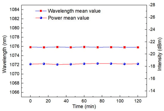
Figure 15.
Laser wavelength and light intensity stability test at 10 °C.
4. Conclusions
In conclusion, we have designed an MZI based on the up-taper structure on Yb doped fiber in an FRL cavity. Different from traditional FRL sensors, in which additional filters are required as sensing units, the designed structure integrates the filter, sensor and gain medium into the laser cavity simultaneously. Thanks to the high thermal–optical coefficient of rare earth ions, the temperature sensitivity of the designed sensor is as high as 0.261 nm/°C. Furthermore, we tested the RI sensitivity and stability, and achieved 151 nm/RIU RI sensitivity. At the same time, the system maintains good stability within 2 h. Benefiting from the characteristics of the FRL itself, the designed structure has an SNR higher than 40 dB and a linewidth narrower than 0.2 nm. This provides an extremely powerful possibility for human life health detection and monitoring the normal operation of aircraft engines.
Author Contributions
Conceptualization, W.L.; methodology, W.L.; validation, W.L. and, Y.L.; formal analysis, W.L. and Y.L.; investigation, W.L. and Y.L.; resources, W.L. and Y.L.; data curation, W.L. and Y.L.; writing—original draft preparation, W.L.; writing—L.S. and P.P.S.; visualization, L.S. and P.P.S.; supervision, L.S.; project administration, L.S.; funding acquisition, L.S. All authors have read and agreed to the published version of the manuscript.
Funding
This work was supported by the startup fund from the Southern University of Science and Technology and the Shenzhen government.
Institutional Review Board Statement
Not applicable.
Informed Consent Statement
Not applicable.
Data Availability Statement
Not applicable.
Acknowledgments
Thanks to Lips team for their help and support to the whole experiment.
Conflicts of Interest
The authors declare no conflict of interest.
References
- Lee, B.; Roh, S.; Park, J. Current status of micro- and nano-structured optical fiber sensors. Opt. Fiber Technol. 2009, 15, 209–221. [Google Scholar] [CrossRef]
- Wang, K.; Dong, X.; Kohler, M.H.; Kienle, P.; Bian, Q.; Jakobi, M.; Koch, A.W. Advances in Optical Fiber Sensors Based on Multimode Interference (MMI): A Review. IEEE Sens. J. 2021, 21, 132–142. [Google Scholar] [CrossRef]
- Dai, J.; Zhu, L.; Wang, G.; Xiang, F.; Qin, Y.; Wang, M.; Yang, M. Optical Fiber Grating Hydrogen Sensors: A Review. Sensors 2017, 17, 577. [Google Scholar] [CrossRef] [PubMed]
- Leal-Junior, A.G.; Marques, C. Diaphragm-Embedded Optical Fiber Sensors: A Review and Tutorial. IEEE Sens. J. 2021, 21, 12719–12733. [Google Scholar] [CrossRef]
- De, M.; Gangopadhyay, T.K.; Singh, V.K. Prospects of Photonic Crystal Fiber as Physical Sensor: An Overview. Sensors 2019, 19, 464. [Google Scholar] [CrossRef] [PubMed]
- Chandani, S.M.; Jaeger, N.A.F. Fiber-optic temperature sensor using evanescent fields in D fibers. IEEE Photonics Technol. Lett. 2005, 17, 2706–2708. [Google Scholar] [CrossRef]
- Rajan, G.; Ramakrishnan, M.; Semenova, Y.; Domanski, A.; Boczkowska, A.; Wolinski, T.; Farrell, G. Analysis of Vibration Measurements in a Composite Material Using an Embedded PM-PCF Polarimetric Sensor and an FBG Sensor. IEEE Sens. J. 2012, 12, 1365–1371. [Google Scholar] [CrossRef]
- Huang, G.; Zhou, B.; Chen, Z.; Jiang, H.; Xing, X. Magnetic-Field Sensor Utilizing the Ferrofluid and Thin-Core Fiber Modal Interferometer. IEEE Sens. J. 2015, 15, 333–336. [Google Scholar] [CrossRef]
- Xu, J.; Huang, K.; Zheng, J.; Li, J.; Pei, L.; You, H.; Ning, T. Sensitivity Enhanced Magnetic Field Sensor Based on Hollow Core Fiber Fabry-Perot Interferometer and Vernier Effect. IEEE Photonics J. 2022, 14, 6841205. [Google Scholar] [CrossRef]
- Zhao, Y.; Lv, R.; Ying, Y.; Wang, Q. Hollow-core photonic crystal fiber Fabry–Perot sensor for magnetic field measurement based on magnetic fluid. Opt. Laser Technol. 2012, 44, 899–902. [Google Scholar] [CrossRef]
- Tien, C.L.; Hwang, C.C.; Chen, H.W.; Liu, W.F.; Lin, S.W. Magnetic Sensor Based on Side-Polished Fiber Bragg Grating Coated with Iron Film. IEEE Trans. Magn. 2006, 42, 3285–3287. [Google Scholar] [CrossRef]
- Sun, D.D.; Ran, Y.; Wang, G.J. Label-Free Detection of Cancer Biomarkers Using an In-Line Taper Fiber-Optic Interferometer and a Fiber Bragg Grating. Sensors 2017, 17, 2559. [Google Scholar] [CrossRef] [PubMed]
- Liang, L.; Jin, L.; Ran, Y.; Sun, L.P.; Guan, B.O. Fiber Light-Coupled Optofluidic Waveguide (FLOW) Immunosensor for Highly Sensitive Detection of p53 Protein. Anal. Chem. 2018, 90, 10851–10857. [Google Scholar] [CrossRef] [PubMed]
- Xue, R.; Nelson, M.T.; Teixeira, S.A.; Viapiano, M.S.; Lannutti, J.J. Cancer cell aggregate hypoxia visualized in vitro via biocompatible fiber sensors. Biomaterials 2016, 76, 208–217. [Google Scholar] [CrossRef]
- Zhang, X.; Wu, Z.; Zhang, B. Strain dependence of fiber Bragg grating sensors at low temperature. Opt. Eng. 2006, 45, 054401. [Google Scholar] [CrossRef]
- Wang, C. Fiber ringdown temperature sensors. Opt. Eng. 2005, 44, 030503. [Google Scholar] [CrossRef]
- Wang, J.; Shen, C.; Lu, Y.; Chen, D.; Zhong, C.; Chu, J.; Dong, X.; Chan, C.C. Liquid Refractive Index Sensor Based on a Polarization-Maintaining Fiber Loop Mirror. IEEE Sens. J. 2013, 13, 1721–1724. [Google Scholar] [CrossRef]
- Yang, X.; Luo, S.; Chen, Z.; Ng, J.H. Refractive index sensor based on fiber laser. Microw. Opt. Technol. Lett. 2007, 49, 916–918. [Google Scholar] [CrossRef]
- Li, Z.; Wang, Y.; Liao, C.; Liu, S.; Zhou, J.; Zhong, X.; Liu, Y.; Yang, K.; Wang, Q.; Yin, G. Temperature-insensitive refractive index sensor based on in-fiber Michelson interferometer. Sens. Actuators B Chem. 2014, 199, 31–35. [Google Scholar] [CrossRef]
- Nath, P.; Singh, H.K.; Datta, P.; Sarma, K.C. All-fiber optic sensor for measurement of liquid refractive index. Sens. Actuators A Phys. 2008, 148, 16–18. [Google Scholar] [CrossRef]
- Huang, T.; Shao, X.; Wu, Z.; Sun, Y.; Zhang, J.; Lam, H.Q.; Hu, J.; Shum, P.P. A sensitivity enhanced temperature sensor based on highly Germania-doped few-mode fiber. Opt. Commun. 2014, 324, 53–57. [Google Scholar] [CrossRef]
- Patrick, H.J.; Williams, G.M.; Kersey, A.D.; Pedrazzani, J.R.; Vengsarkar, A.M. Hybrid fiber Bragg grating/long period fiber grating sensor for strain/temperature discrimination. IEEE Photonics Technol. Lett. 1996, 8, 1223–1225. [Google Scholar] [CrossRef]
- Cao, Z.; Zhang, Z.; Ji, X.; Shui, T.; Wang, R.; Yin, C.; Zhen, S.; Lu, L.; Yu, B. Strain-insensitive and high temperature fiber sensor based on a Mach–Zehnder modal interferometer. Opt. Fiber Technol. 2014, 20, 24–27. [Google Scholar] [CrossRef]
- Ayupova, T.; Sypabekova, M.; Molardi, C.; Bekmurzayeva, A.; Shaimerdenova, M.; Dukenbayev, K.; Tosi, D. Wavelet-Based Demodulation of Multimode Etched Fiber Bragg Grating Refractive Index Sensor. Sensors 2018, 19, 39. [Google Scholar] [CrossRef]
- Milenko, K.; Wolinski, T.R.; Shum, P.P.; Hu, D.J.J. Temperature-Sensitive Photonic Liquid Crystal Fiber Modal Interferometer. IEEE Photonics J. 2012, 4, 1855–1860. [Google Scholar] [CrossRef]
- Wolinski, T.R.; Domanski, A.W.; Konopka, W.; Bock, W.J. Prototype fiber optic liquid crystalline sensor for pressure monitoring. IEEE Trans. Instrum. Meas. 1999, 48, 684–687. [Google Scholar] [CrossRef]
- Mathews, S.; Farrell, G.; Semenova, Y. Directional Electric Field Sensitivity of a Liquid Crystal Infiltrated Photonic Crystal Fiber. IEEE Photonics Technol. Lett. 2011, 23, 408–410. [Google Scholar] [CrossRef]
- Hu, X.-G.; Zhao, Y.; Peng, Y.; Tong, R.-J.; Zheng, H.-K.; Zhao, J.; Hu, S. In-fiber optofluidic michelson interferometer for detecting small volume and low concentration chemicals with a fiber ring cavity laser. Sens. Actuators B Chem. 2022, 370, 132467. [Google Scholar] [CrossRef]
- Meng, D.; Zhang, X.; Wang, D.; Miao, C.; Shi, J.; Li, X.; Bai, H.; Chen, H.; Guo, C.; Yao, J. Gas Pressure Sensor with Low Detection Limit Based on Fabry-Perot Interferometer and Intracavity Sensing of Fiber Ring Laser. IEEE Sens. J. 2022, 22, 6606–6611. [Google Scholar] [CrossRef]
- Yibin, L.; Lin, W.; Vai, M.I.; Shum, P.P.; Shao, L.-Y.; He, W.; Liu, S.; Zhao, F.; Wang, W.; Yuhui, L. Fiber Optic Electric Field Intensity Sensor Based on Liquid Crystal-Filled Photonic Crystal Fiber Incorporated Ring Laser. IEEE Photonics J. 2022, 14, 6808305. [Google Scholar] [CrossRef]
- Yan, W.; Han, Q.; Chen, Y.; Song, H.; Tang, X.; Liu, T. Fiber-loop ring-down interrogated refractive index sensor based on an SNS fiber structure. Sens. Actuators B Chem. 2018, 255, 2018–2022. [Google Scholar] [CrossRef]
- Madry, M.; Alwis, L.; Binetti, L.; Pajewski, L.; Beres-Pawlik, E. Simultaneous Measurement of Temperature and Relative Humidity Using a Dual-Wavelength Erbium-Doped Fiber Ring Laser Sensor. IEEE Sens. J. 2019, 19, 9215–9220. [Google Scholar] [CrossRef]
- Zhao, Y.; Cai, L.; Li, X.-G. In-Fiber Mach–Zehnder Interferometer Based on Up-Taper Fiber Structure with Er3+ Doped Fiber Ring Laser. J. Light. Technol. 2016, 34, 3475–3481. [Google Scholar] [CrossRef]
Publisher’s Note: MDPI stays neutral with regard to jurisdictional claims in published maps and institutional affiliations. |
© 2022 by the authors. Licensee MDPI, Basel, Switzerland. This article is an open access article distributed under the terms and conditions of the Creative Commons Attribution (CC BY) license (https://creativecommons.org/licenses/by/4.0/).