
Smart Pneumatic Artificial Muscle Using a Bend Sensor like a Human Muscle with a Muscle Spindle

 , ,
, ,
Abstract
1. Introduction
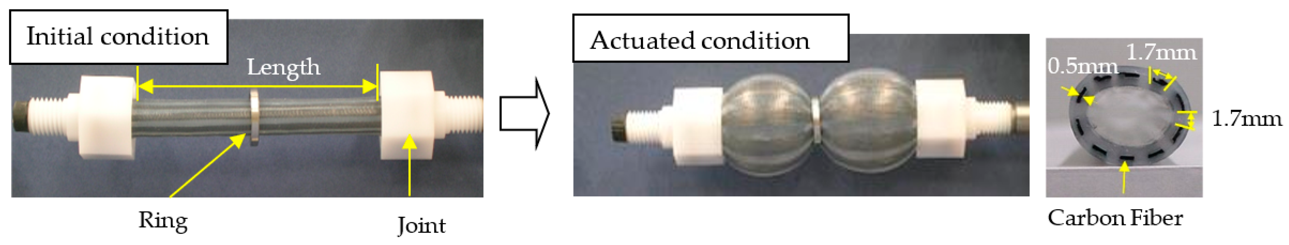
2. Pneumatic Artificial Muscle Reinforced by Carbon Fibers
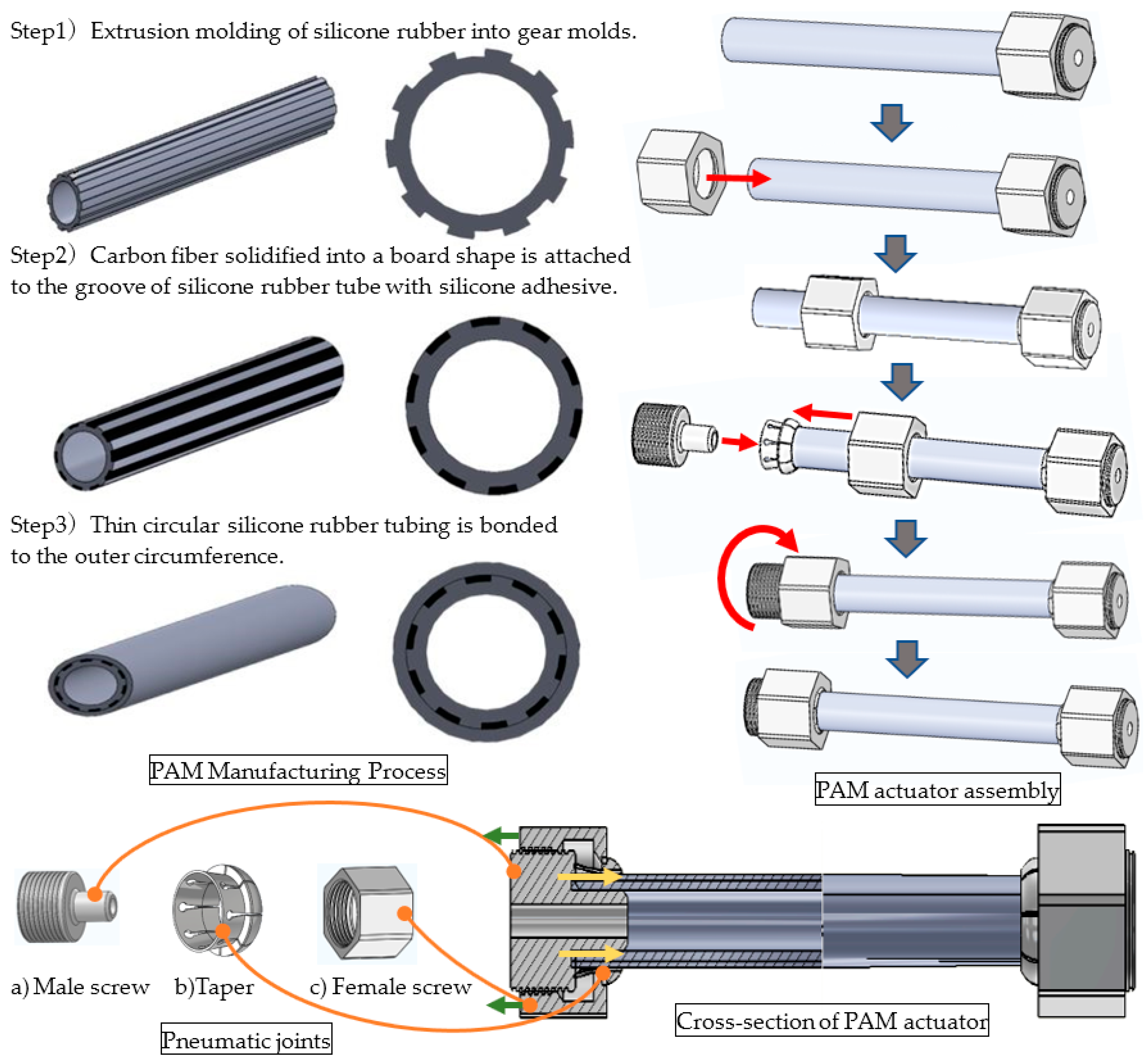
2.1. Simplified Manufacturing Method and Detailed Configuration
2.2. Fundamental Characteristics
3. Strain-Gage-Type Bend Sensor
3.1. Circuit
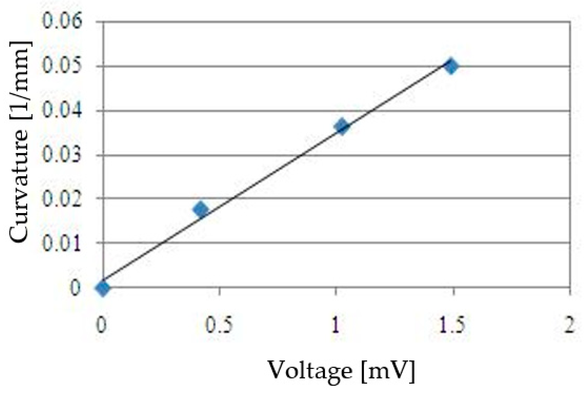
3.2. Calibration
4. Estimation Method of Contraction from Curvature
5. Estimation Method of Contraction from the Curvature
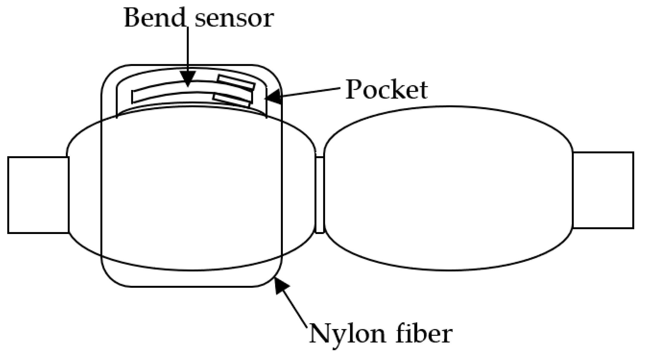
5.1. Mounting the Bend Sensor to a PAM
5.2. Evaluation
6. Conclusions
- (1)
- The developed bend sensor can be implemented easily in a PAM. Furthermore, a smart PAM system using the bend sensor can estimate PAM contraction based on curvature measured by the flat flexible bending sensor. The contraction can be measured without prevention of contraction of the muscle because the bending sensor is not bonded to the PAM and is allowed to slip due to bending deformation.
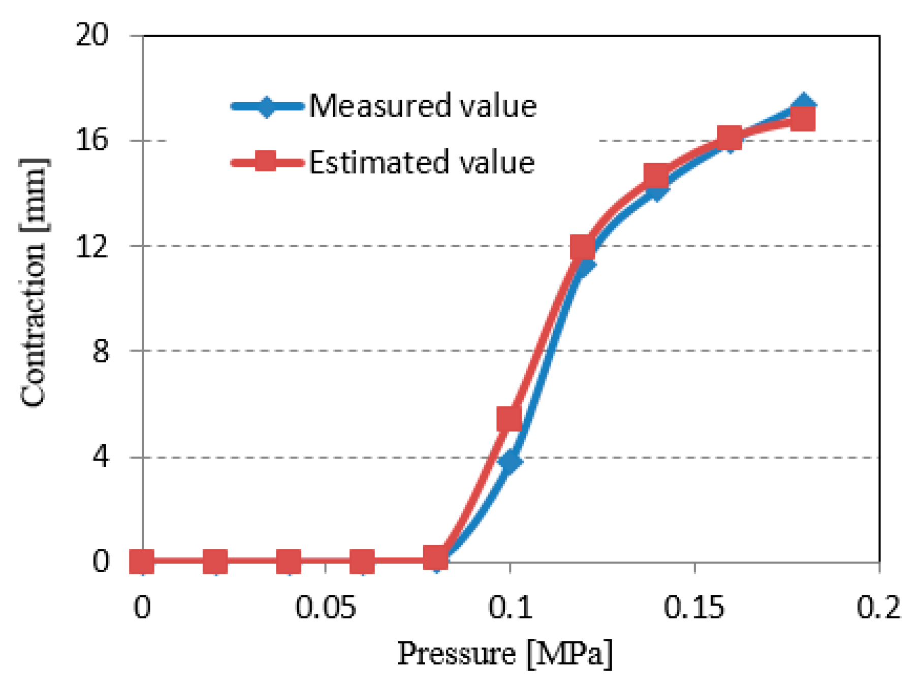
- (2)
- Estimated contraction, as calculated based on curvature measured by the bend sensor, was compared with actual measured contraction. Estimated contraction was close to actual measured contraction at all input air pressures. These results indicate that the proposed smart PAM system can detect excessive contraction in the system and prevent injury to the muscle.
Author Contributions
Funding
Institutional Review Board Statement
Informed Consent Statement
Acknowledgments
Conflicts of Interest
References
- Shin, D.; Quek, Z.F.; Phan, S.; Cutkosky, M.; Khatib, O. Instantaneous stiffness effects on impact forces in human-friendly robots. In Proceedings of the 2011 IEEE/RSJ International Conference on Intelligent Robots and Systems, San Francisco, CA, USA, 25–30 September 2011; pp. 2998–3003. [Google Scholar]
- Ren-Jeng, W.; Han-Pang, H. Active Variable Stiffness Elastic Actuator: Design and application for safe physical human-robot interaction. In Proceedings of the 2010 IEEE International Conference on Robotics and Biomimetics, Tianjin, China, 14–18 December 2010; pp. 1417–1422. [Google Scholar]
- Duchaine, V.; Lauzier, N.; Baril, M.; Lacasse, M.; Gosselin, C. A flexible robot skin for safe physical human robot interaction. In Proceedings of the 2009 IEEE International Conference on Robotics and Automation, Kobe, Japan, 12–17 May 2009; pp. 3676–3681. [Google Scholar]
- Carlo, F.; Walter, F.; Andrea, M.B. Flexible Pneumatic Actuators: A Comparison between The McKibben and the Straight Fibres Muscle. J. Robot. Mechatron. 2001, 13, 56–63. [Google Scholar]
- Schulte, H.F. The Characteristics of the McKibben Artificial Muscle. In The Application of External Power in Prosthetics and Orthotics; National Academy of Sciences: Washington, DC, USA, 1961; pp. 94–115. [Google Scholar]
- Kluge, G.K.; Czernieki, J.M.; Hannaford, B. McKibben Artificial Muscles: Pneumatic Actuators with Biomechanical Intelligence. In Proceedings of the 1999 IEEE/ASME International Conference on Advanced Intelligent Mechatronics, Atlanta, GA, USA, 19–23 September 1999; pp. 221–226. [Google Scholar]
- Noritsugu, T.; Ando, F.; Yoshikawa, T. Control Performance of Rubber Artificial Muscle. Trans. Jpn. Soc. Mech. Eng. Ser. C 1994, 60, 193–198. [Google Scholar] [CrossRef][Green Version]
- Kubota, M.; Hiroki, F.; Kagawa, T.; Sawada, K. Fuzzy Control for A Robot Manipulator with Artificial Rubber Muscles. In Proceedings of the 3rd JFPS International Symposium on Fluid Power, Yokohama, Japan, 3–6 November 1996; pp. 241–246. [Google Scholar]
- Tondu, B.; Lopez, P. Modeling and control of McKibben artificial muscle robot actuators. IEEE Control. Syst. 2000, 20, 15–38. [Google Scholar]
- Saga, N.; Nagase, J.; Saikawa, T. Pneumatic Artificial Muscles based on Biomechanical Characteristics of Human Muscles. Appl. Bionics Biomech. 2006, 3, 191–197. [Google Scholar] [CrossRef][Green Version]
- Saga, N.; Saikawa, T. Development of a Pneumatic Artificial Muscle based on Biomechanical characteristics. Adv. Robot. 2008, 22, 761–770. [Google Scholar] [CrossRef]
- Saga, N.; Nakamura, T.; Yaegashi, K. Mathematical Model of Pneumatic Artificial Muscle Reinforced by Straight Fibers. J. Intell. Mater. Syst. Struct. 2007, 18, 175–180. [Google Scholar] [CrossRef]
- Chou, C.-P.; Hannaford, B. Measurement and modeling of mck-ibben pneumatic artificial muscles. IEEE Trans. Robot. Autom. 1996, 12, 90–102. [Google Scholar] [CrossRef]
- Park, Y.-L.; Chen, B.-R.; Pérez-Arancibia, N.O.; Young, D.; Stirling, L.; Wood, R.J.; Goldfield, E.C.; Nagpal, R. Design and control of a bio-inspired soft wearable robotic device for ankle—Foot rehabilitation. Bioinspir. Biomim. 2014, 9, 016007. [Google Scholar] [CrossRef] [PubMed]
- Herr, H.M.; Kornbluh, R.D. New horizons for orthotic and prosthetic technology: Artificial muscle for ambulation. In Smart Structures and Materials; International Society for Optics and Photonics: Bellingham, WA, USA, 2004; pp. 1–9. [Google Scholar]
- Yano, T.; Fujimoto, S.; Akagi, T.; Kobayashi, W. Development of outer diameter sensor for position control of mckibben artificial actuator using hall-effect sensor. Int. J. Mech. Eng. Robot. Res. 2020, 9, 190–196. [Google Scholar] [CrossRef]
- Ozel, S.; Keskin, N.A.; Khea, D.; Onal, C.D. A Precise Embedded Curvature Sensor Module for Soft-Bodied Robots. Sens. Actuators A Phys. 2015, 236, 349–356. [Google Scholar] [CrossRef]
- Park, Y.-L.; Wood, R.J. Smart pneumatic artificial muscle actuator with embedded microfluidic sensing. In Proceedings of the Sensors 2013 IEEE, Baltimore, MD, USA, 3–6 November 2013; pp. 1–4. [Google Scholar]
- Hu, W.; Alici, G. Bioinspired three-dimensional-printed helical soft pneumatic actuators and their characterization. Soft Robot. 2020, 7, 267–282. [Google Scholar] [CrossRef] [PubMed]
- Hitzmann, A.; Wang, Y.; Kessler, T.; Hosoda, K. Using conductive fabrics as inflation sensors for pneumatic artificial muscles. Adv. Robot. 2021, 35, 995–1011. [Google Scholar] [CrossRef]
- Felt, W.; Chin, K.Y.; Remy, C.D. Contraction sensing with smart braid mckibben muscles. IEEE/ASME Trans. Mechatron. 2015, 21, 1201–1209. [Google Scholar] [CrossRef] [PubMed]
- Felt, W.; Lu, S.; Remy, C.D. Modeling and design of smart braid” inductance sensors for fiber-reinforced elastomeric enclosures. IEEE Sens. J. 2018, 18, 2827–2835. [Google Scholar] [CrossRef]


| Length | 100 mm |
| Outer Diameter | 12 mm |
| Thickness | 2 mm |
| Weight (With Ring and Joint Part) | 38 g |
| Pneumatic Joints | POM |
| Type of Rubber | Silicon Rubber |
| Type of Fiber | Carbon Fiber |
| Number of Fiber Bundles | 10 |
Publisher’s Note: MDPI stays neutral with regard to jurisdictional claims in published maps and institutional affiliations. |
© 2022 by the authors. Licensee MDPI, Basel, Switzerland. This article is an open access article distributed under the terms and conditions of the Creative Commons Attribution (CC BY) license (https://creativecommons.org/licenses/by/4.0/).
Share and Cite
Saga, N.; Shimada, K.; Inamori, D.; Saito, N.; Satoh, T.; Nagase, J.-y. Smart Pneumatic Artificial Muscle Using a Bend Sensor like a Human Muscle with a Muscle Spindle. Sensors 2022, 22, 8975. https://doi.org/10.3390/s22228975
Saga N, Shimada K, Inamori D, Saito N, Satoh T, Nagase J-y. Smart Pneumatic Artificial Muscle Using a Bend Sensor like a Human Muscle with a Muscle Spindle. Sensors. 2022; 22(22):8975. https://doi.org/10.3390/s22228975
Chicago/Turabian StyleSaga, Norihiko, Kunio Shimada, Douhaku Inamori, Naoki Saito, Toshiyuki Satoh, and Jun-ya Nagase. 2022. "Smart Pneumatic Artificial Muscle Using a Bend Sensor like a Human Muscle with a Muscle Spindle" Sensors 22, no. 22: 8975. https://doi.org/10.3390/s22228975
APA StyleSaga, N., Shimada, K., Inamori, D., Saito, N., Satoh, T., & Nagase, J.-y. (2022). Smart Pneumatic Artificial Muscle Using a Bend Sensor like a Human Muscle with a Muscle Spindle. Sensors, 22(22), 8975. https://doi.org/10.3390/s22228975