
Development and Analysis of Electrochemical Reactor with Vibrating Functional Element for AAO Nanoporous Membranes Fabrication

 ,
, 
Abstract
:1. Introduction
2. Materials and Methods
2.1. Design of Electrochemical Reactor
2.2. Experimental Setup
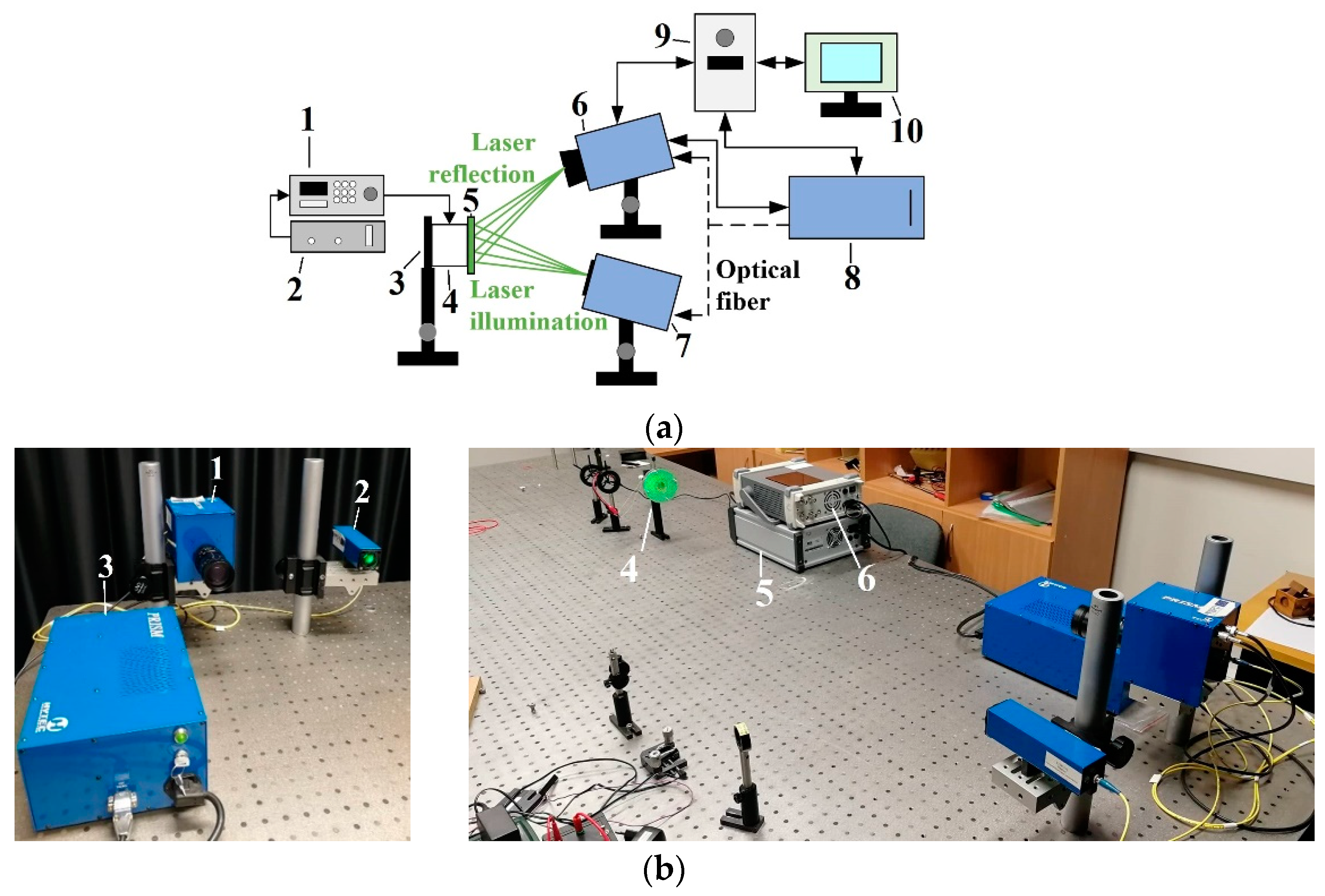
2.3. Experimental Setup for Vibration Measurements
2.4. Simulation Method and Conditions of Vibration Process
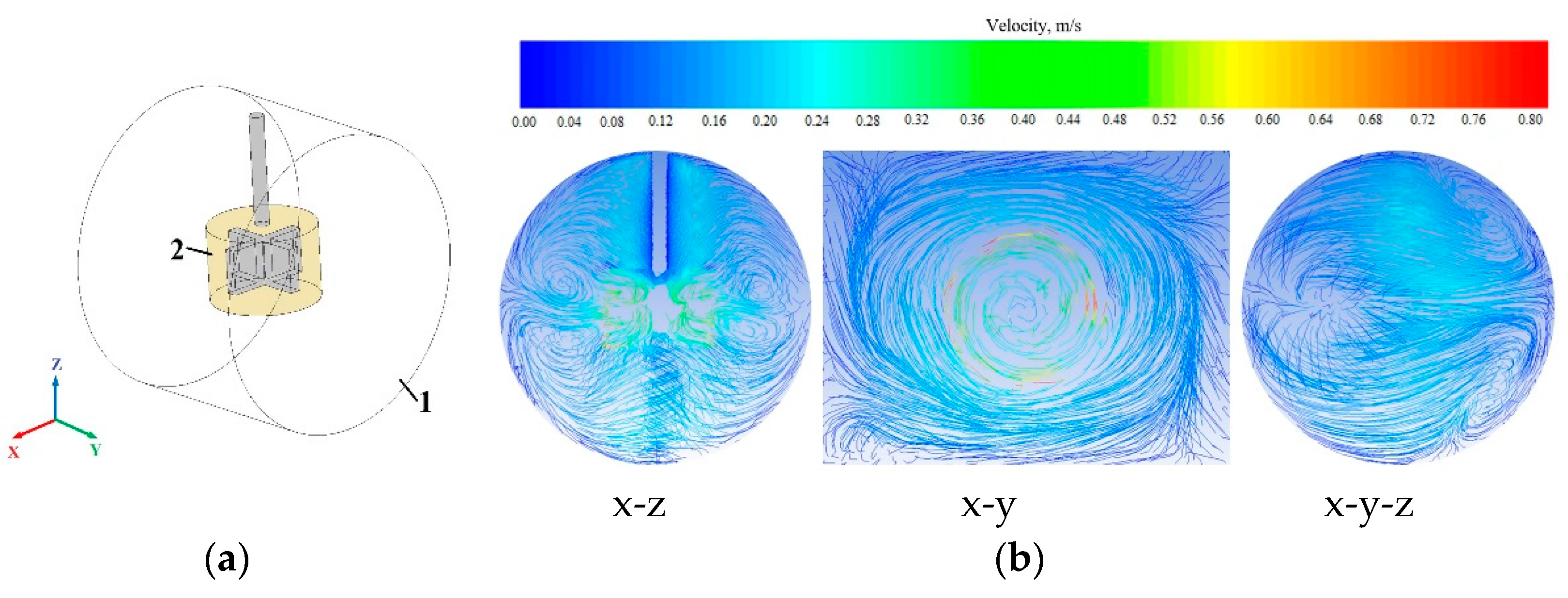
2.5. Simulation Method and Conditions of Mixing Process
3. Results and Discussion
3.1. Vibration Analysis
3.2. Mixing Analysis
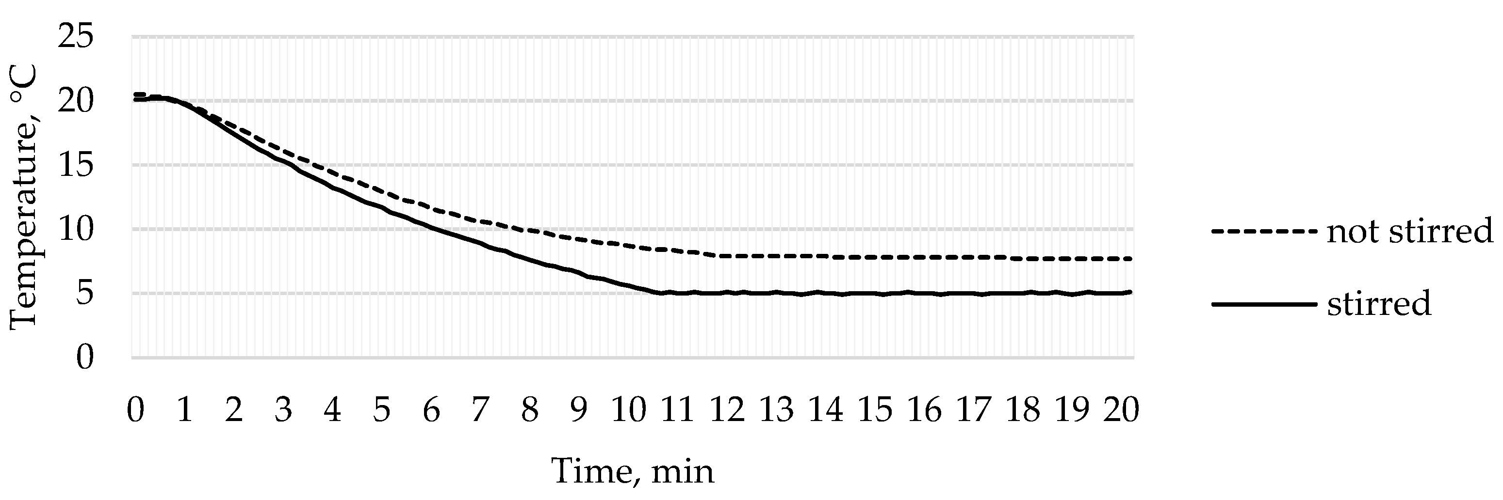
3.3. Temperature Analysis
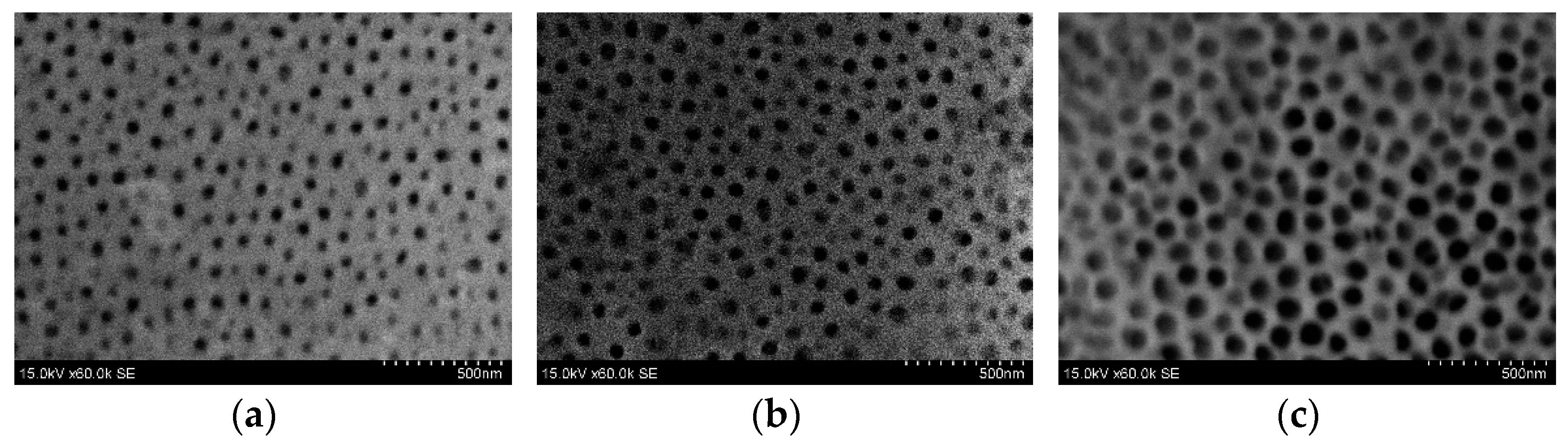
3.4. Fabrication of AAO Nanoporous Membrane
4. Conclusions
- The high-frequency excitation method was used during the vibration experiment. Five vibration mode shapes were obtained at different frequencies: the first mode shape (0, 1) at 3.0 kHz and 3.1 kHz, the second mode shape (1, 1) at 4.8 kHz and 4.1 kHz, the third mode shape (2, 1) at 6.5 kHz and 6.3 kHz, the fourth mode shape (0, 2) at 6.9 kHz and 7.1 kHz, and the fifth mode shape (3, 1) at 8.8 kHz and 9.1 kHz. The simulation and the experimental results of membrane surface displacements were close, but not identical, because of nonideal structural stability and material properties and the inaccuracy of the measuring equipment;
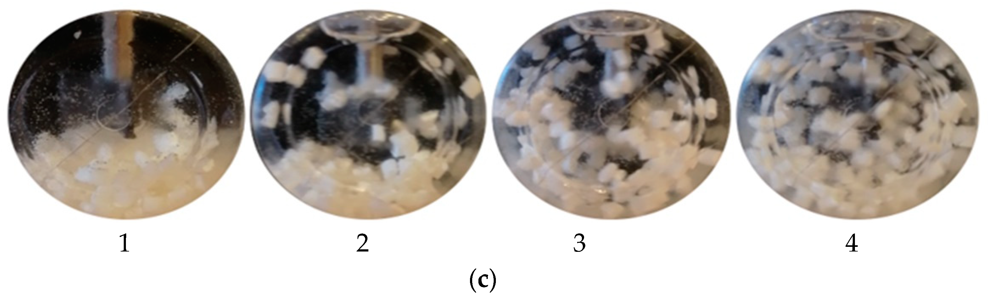
- It was found that the designed impeller was sufficient for the mixing process. The whole volume in the reactor was mixed. However, specific particle motions were not clearly captured during the experiment. When the mixing device was turned off, the particles did not move throughout the reactor volume, but in the case of the mixing process, the particles were distributed throughout the reactor volume. It was assumed that the mixing experiment was related to the simulation results;
- In the case where the liquid in the reactor was not stirred, the uniform temperature of 5 °C was not reached during the experiment. In addition, in some places, the temperature in the reactor was significantly lower, and cold zones with ice were formed. The temperature sensor recorded the lowest temperature of 7.7 °C. In the case where the liquid was stirred inside the reactor, the temperature ranged from 4.5 °C to 6.0 °C using an automatic temperature control system. Such temperature changes were acceptable.
Author Contributions
Funding
Institutional Review Board Statement
Informed Consent Statement
Data Availability Statement
Conflicts of Interest
References
- Domagalski, J.T.; Xifre-Perez, E.; Marsal, L.F. Recent Advances in Nanoporous Anodic Alumina: Principles, Engineering, and Applications. Nanomaterials 2021, 11, 430. [Google Scholar] [CrossRef] [PubMed]
- Tan, C.; Cao, X.; Wu, X.; He, Q.; Yang, J.; Zhang, X.; Chen, J.; Zhao, W.; Han, S.; Nam, G.; et al. Recent Advances in Ultrathin Two-Dimensional Nanomaterials. Chem. Rev. 2017, 117, 6225–6331. [Google Scholar] [CrossRef] [PubMed]
- Zhang, H. Ultrathin Two-Dimensional Nanomaterials. ACS Nano 2015, 9, 9451–9469. [Google Scholar] [CrossRef] [PubMed]
- Hwang, S.; Lee, C.; Cheng, H.; Jeong, J.; Kang, S.; Kim, J.; Shin, J.; Yang, J.; Liu, Z.; Ameer, G.; et al. Biodegradable Elastomers and Silicon Nanomembranes/Nanoribbons for Stretchable, Transient Electronics, and Biosensors. Nano Lett. 2015, 15, 2801–2808. [Google Scholar] [CrossRef]
- Zanghelini, F.; Frías, I.; Rêgo, M.; Pitta, M.; Sacilloti, M.; Oliveira, M.; Andrade, C. Biosensing breast cancer cells based on a three-dimensional TIO2 nanomembrane transducer. Biosens. Bioelectron. 2017, 92, 313–320. [Google Scholar] [CrossRef]
- Vervacke, C.; Bufon, C.; Thurmer, D.; Schmidt, O. Three-dimensional chemical sensors based on rolled-up hybrid nanomembranes. RSC Adv. 2014, 4, 9723. [Google Scholar] [CrossRef]
- Liu, X.; Ma, T.; Xu, Y.; Sun, L.; Zheng, L.; Schmidt, O.; Zhang, J. Rolled-up SnO2 nanomembranes: A new platform for efficient gas sensors. Sens. Actuators B Chem. 2018, 264, 92–99. [Google Scholar] [CrossRef]
- Tian, F.; Lyu, J.; Shi, J.; Tan, F.; Yang, M. A polymeric microfluidic device integrated with nanoporous alumina membranes for simultaneous detection of multiple foodborne pathogens. Sens. Actuators B Chem. 2016, 225, 312–318. [Google Scholar] [CrossRef]
- Pérez-Madrigal, M.; Armelin, E.; Puiggalí, J.; Alemán, C. Insulating and semiconducting polymeric free-standing nanomembranes with biomedical applications. J. Mater. Chem. B 2015, 3, 5904–5932. [Google Scholar] [CrossRef] [Green Version]
- Madrigal, M.; Giannotti, M.; Valle, L.; Franco, L.; Armelin, E.; Puiggalí, J.; Sanz, F.; Alemán, C. Thermoplastic Polyurethane: Polythiophene Nanomembranes for Biomedical and Biotechnological Applications. ACS Appl. Mater. Interfaces 2014, 6, 9719–9732. [Google Scholar] [CrossRef]
- Kumar, L. Role and adverse effects of nanomaterials in food technology. J. Toxicol. Health 2015, 2, 2. [Google Scholar] [CrossRef] [Green Version]
- Wang, X.; Chen, Y.; Schmid, O.; Yan, C. Engineered nanomembranes for smart energy storage devices. Chem. Soc. Rev. 2016, 45, 1308–1330. [Google Scholar] [CrossRef] [PubMed]
- Thibert, S.; Delaunay, M.; Ghis, A. Carbon-metal vibrating nanomembranes for high frequency microresonators. Diam. Relat. Mater. 2018, 81, 138–145. [Google Scholar] [CrossRef]
- Jakšić, Z.; Jakšić, O. Biomimetic Nanomembranes: An Overview. Biomimetics 2020, 5, 24. [Google Scholar] [CrossRef] [PubMed]
- Jakšić, Z.; Matovic, J. Functionalization of Artificial Freestanding Composite Nanomembranes. Materials 2010, 3, 165–200. [Google Scholar] [CrossRef] [Green Version]
- Huang, G.; Mei, Y. Assembly and Self-Assembly of Nanomembrane Materials-From 2D to 3D. Small 2018, 14, 1703665. [Google Scholar] [CrossRef] [PubMed]
- Winter, A.; Ekinci, Y.; Gölzhäuser, A.; Turchanin, A. Freestanding carbon nanomembranes and graphene monolayers nanopatterned via EUV interference lithography. 2D Mater. 2019, 6, 021002. [Google Scholar] [CrossRef] [Green Version]
- Yang, L.; Wei, J.; Ma, Z.; Song, P.; Ma, J.; Zhao, Y.; Huang, Z.; Zhang, M.; Yang, F.; Wang, X. The Fabrication of Micro/Nano Structures by Laser Machining. Nanomaterials 2019, 9, 1789. [Google Scholar] [CrossRef] [Green Version]
- Chan, E.; Lee, S. Thickness-dependent swelling of molecular layer-by-layer polyamide nanomembranes. J. Polym. Sci. Part B Polym. Phys. 2016, 55, 412–417. [Google Scholar] [CrossRef]
- Chen, X.; Zhang, W.; Lin, Y.; Cai, Y.; Qiu, M.; Fan, Y. Preparation of high-flux γ-alumina nanofiltration membranes by using a modified sol-gel method. Microporous Mesoporous Mater. 2015, 214, 195–203. [Google Scholar] [CrossRef]
- Tijing, L.; Dizon, J.; Ibrahim, I.; Nisay, A.; Shon, H.; Advincula, R. 3D printing for membrane separation, desalination and water treatment. Appl. Mater. Today 2020, 18, 100486. [Google Scholar] [CrossRef]
- Lee, J.; Tan, W.; An, J.; Chua, C.; Tang, C.; Fane, A.; Chong, T. The potential to enhance membrane module design with 3D printing technology. J. Membr. Sci. 2016, 499, 480–490. [Google Scholar] [CrossRef]
- Lee, W.; Park, S. Porous Anodic Aluminum Oxide: Anodization and Templated Synthesis of Functional Nanostructures. Chem. Rev. 2014, 114, 7487–7556. [Google Scholar] [CrossRef] [PubMed]
- Velleman, L.; Triani, G.; Evans, P.; Shapter, J.; Losic, D. Structural and chemical modification of porous alumina membranes. Microporous Mesoporous Mater. 2009, 126, 87–94. [Google Scholar] [CrossRef]
- Jani, A.; Anglin, E.; Mclnnes, S.; Losic, D.; Shapter, J.; Voelcker, N. Nanoporous anodic aluminium oxide membranes with layered surface chemistry. Chem. Commun. 2009, 2009, 3062–3064. [Google Scholar] [CrossRef]
- Ateş, S.; Baran, E.; Yazıcı, B. The nanoporous anodic alumina oxide formed by two-step anodization. Thin Solid Film. 2018, 648, 94–102. [Google Scholar] [CrossRef]
- Sulka, G. Highly Ordered Anodic Porous Alumina Formation by Self-Organized Anodizing. In Nanostructured Materials in Electrochemistry; Eftekhari, A., Ed.; Wiley-VCH Verlag GmbH & Co.: Hoboken, NJ, USA, 2008; pp. 1–116. [Google Scholar] [CrossRef]
- Stępniowski, W.; Forbot, D.; Norek, M.; Michalska-Domańska, M.; Król, A. The impact of viscosity of the electrolyte on the formation of nanoporous anodic aluminum oxide. Electrochim. Acta 2014, 133, 57–64. [Google Scholar] [CrossRef]
- Azami, H.; Omidkhah, M. Modeling and optimization of characterization of nanostructure anodized aluminium oxide membranes. J. Iran. Chem. Soc. 2019, 16, 985–997. [Google Scholar] [CrossRef]
- Stępniowski, W.; Moneta, M.; Norek, M.; Michalska-Domańska, M.; Scarpellini, A.; Salerno, M. The influence of electrolyte composition on the growth of nanoporous anodic alumina. Electrochim. Acta 2016, 211, 453–460. [Google Scholar] [CrossRef]
- Absalan, G.; Barzegar, S.; Moradi, M.; Behaein, S. Fabricating Al2O3-nanopores array by an ultrahigh voltage two-step anodization technique: Investigating the effect of voltage rate and Al foil thickness on geometry and ordering of the array. Mater. Chem. Phys. 2017, 199, 265–271. [Google Scholar] [CrossRef]
- Michalska-Domańska, M.; Norek, M.; Stępniowski, W.; Budner, B. Fabrication of high quality anodic aluminum oxide (AAO) on low purity aluminum-A comparative study with the AAO produced on high purity aluminum. Electrochim. Acta 2013, 105, 424–432. [Google Scholar] [CrossRef]
- Patel, Y.; Janusas, G.; Palevicius, A.; Vilkauskas, A. Development of Nanoporous AAO Membrane for Nano Filtration Using the Acoustophoresis Method. Sensors 2020, 20, 3833. [Google Scholar] [CrossRef] [PubMed]
- Kuscer, D.; Rojac, T.; Belavič, D.; Zarnik, M.; Bradeško, A.; Kos, T.; Malič, B.; Boerrigter, M.; Martin, D.; Faccini, M. Integrated piezoelectric vibration system for fouling mitigation in ceramic filtration membranes. J. Membr. Sci. 2017, 540, 277–284. [Google Scholar] [CrossRef]
- Ogawa, J.; Kanno, I.; Kotera, H.; Wasa, K.; Suzuki, T. Development of liquid pumping devices using vibrating microchannel walls. Sens. Actuators A Phys. 2009, 152, 211–218. [Google Scholar] [CrossRef]
- Cazorla, P.; Fuchs, O.; Cochet, M.; Maubert, S.; Rhun, G.; Fouillet, Y.; Defay, E. Integration of PZT thin films on a microfluidic complex system. In Proceedings of the 2014 IEEE International Ultrasonics Symposium, Chicago, IL, USA, 3–6 September 2014. [Google Scholar] [CrossRef]
- Janusas, T.; Pilkauskas, K.; Janusas, G.; Palevicius, A. Active PZT Composite Microfluidic Channel for Bioparticle Manipulation. Sensors 2019, 19, 2020. [Google Scholar] [CrossRef] [Green Version]
- Sathyanarayana, C.; Raja, S.; Ragavendra, H. Procedure to Use PZT Sensors in Vibration and Load Measurements. Smart Mater. Res. 2013, 2013, 173605. [Google Scholar] [CrossRef]
- Wang, G.; Zhao, Z.; Tan, J.; Cui, S.; Wu, H. A novel multifunctional piezoelectric composite device for mechatronics systems by using one single PZT ring. Smart Mater. Struct. 2020, 29, 055027. [Google Scholar] [CrossRef]
- Shen, L.; Li, Y.; Zhong, W.; Wu, J.; Cheng, J.; Jin, L.; Hu, X.; Ling, Z. Fabrication of micro/nanoporous templates with a novel hierarchical structure by anodization of a patterned aluminum surface. Electrochem. Commun. 2021, 126, 107014. [Google Scholar] [CrossRef]
- Mijangos, C.; Hernández, R.; Martín, J. A review on the progress of polymer nanostructures with modulated morphologies and properties, using nanoporous AAO templates. Prog. Polym. Sci. 2016, 54–55, 148–182. [Google Scholar] [CrossRef]
- Wei, Q.; Fu, Y.; Zhang, G.; Yang, D.; Meng, G.; Sun, S. Rational design of novel nanostructured arrays based on porous AAO templates for electrochemical energy storage and conversion. Nano Energy 2019, 55, 234–259. [Google Scholar] [CrossRef]
- Callister, W.D.; Rethwisch, D.G. Fundamentals of Materials Science and Engineering: An Integrated Approach, 5th ed.; Wiley: New York, NY, USA, 2018; pp. 214–216. ISBN 978-1-119-17550-6. [Google Scholar]
- Ge, J.; Ding, B.; Hou, S.; Luo, M.; Nam, D.; Duan, H.; Gao, H.; Lam, Y.C.; Li, H. Rapid fabrication of complex nanostructures using room-temperature ultrasonic nanoimprinting. Nat. Commun. 2021, 12, 3146. [Google Scholar] [CrossRef] [PubMed]
- Dai, J.; Singh, J.; Yamamoto, N. Non-brittle Nanopore Deformation of Anodic Aluminum Oxide Membranes. J. Am. Ceram. Soc. 2017, 101, 2170–2180. [Google Scholar] [CrossRef]
- Poinern, G.; Ali, N.; Fawcett, D. Progress in Nano-Engineered Anodic Aluminum Oxide Membrane Development. Materials 2011, 4, 487–526. [Google Scholar] [CrossRef] [PubMed] [Green Version]
- DeAngelis, D.; Schulze, G. Performance of PZT8 Versus PZT4 Piezoceramic Materials in Ultrasonic Transducers. Phys. Procedia 2016, 87, 85–92. [Google Scholar] [CrossRef]
- Jirout, T.; Jiroutová, D. Application of Theoretical and Experimental Findings for Optimization of Mixing Processes and Equipment. Processes 2020, 8, 955. [Google Scholar] [CrossRef]
- Xavior, M.; Nishanth, D.; Kumar, N.; Jeyapandiarajan, P. Synthesis and Testing of FGM made of ABS Plastic Material. Mater. Today Proc. 2020, 22, 1838–1844. [Google Scholar] [CrossRef]
- Kozhukhova, A.E.; Preez, S.P.; Bessarabov, D.G. Preparation of anodized aluminium oxide at high temperatures using low purity aluminium (Al6082). Surf. Coat. Technol. 2019, 378, 124970. [Google Scholar] [CrossRef]
- Ko, S.; Lee, D.; Jee, S.; Park, H.; Lee, K.; Hwang, W. Mechanical properties and residual stress in porous anodic alumina structures. Thin Solid Film. 2006, 515, 1932–1937. [Google Scholar] [CrossRef]
- Vojkuvka, L.; Santos, A.; Pallarès, J.; Ferré-Borrulla, J.; Marsal, L.F.; Celis, J.P. On the mechanical properties of nanoporous anodized alumina by nanoindentation and sliding tests. Surf. Coat. Technol. 2012, 206, 2115–2124. [Google Scholar] [CrossRef]
- Tsyntsaru, N.; Kavas, B.; Sort, J.; Urgen, M.; Celis, J.P. Mechanical and frictional behaviour of nano-porous anodised aluminium. Mater. Chem. Phys. 2014, 148, 887–895. [Google Scholar] [CrossRef]


| Parameter | Unit | Values |
|---|---|---|
| Membrane radius | mm | 20 |
| Membrane thickness | mm | 0.5 |
| Material Young’s modulus | MPa | 68,000 |
| Material mass density | kg/m3 | 2712 |
| Material Poisson’s ratio | - | 0.33 |
| Radial direction pretension load | MPa | 38 |
| Common factor in natural frequency | Hz | 1256 |
| 1st natural frequency mode, mode shape (0, 1) | Hz | 3020 |
| 2nd natural frequency mode, mode shape (1, 1) | Hz | 4812 |
| 3rd natural frequency mode, mode shape (2, 1) | Hz | 6450 |
| 4th natural frequency mode, mode shape (0, 2) | Hz | 6933 |
| 5th natural frequency mode, mode shape (3, 1) | Hz | 8835 |
| Simulation Results by Using COMSOL Multiphysics 5.4 Software | ||||
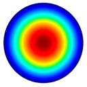 3.0 kHz 3.0 kHz | 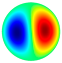 4.8 kHz 4.8 kHz | 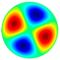 6.5 kHz 6.5 kHz |  6.9 kHz 6.9 kHz | 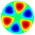 8.8 kHz 8.8 kHz |
| Experimental Results by Using the PRISM System | ||||
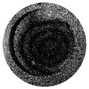 3.1 kHz 3.1 kHz |  4.1 kHz 4.1 kHz |  6.3 kHz 6.3 kHz | 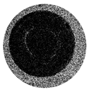 7.1 kHz 7.1 kHz | 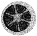 9.1 kHz 9.1 kHz |
| Parameter | No Frequency Excitation | Frequency Excitation at 3.1 kHz | Frequency Excitation at 4.1 kHz |
|---|---|---|---|
| Pore diameter (nm) | 55.0 ± 10 | 82.6 ± 10 | 86.1 ± 10 |
| Interpore distance (nm) | 121.4 ± 20 | 120.0 ± 20 | 120.5 ± 20 |
| Porosity (%) | 19 | 43 | 46 |
| Element | No Frequency | Frequency Excitation at 3.1 kHz | Frequency Excitation at 4.1 kHz | |||
|---|---|---|---|---|---|---|
| Atomic Concentration, at% | Error, % | Atomic Concentration, at% | Error, % | Atomic Concentration, at% | Error, % | |
| Carbon | 1.37 | 0.2 | 2.02 | 0.5 | 1.36 | 0.3 |
| Oxygen | 62.77 | 6.1 | 65.18 | 7.8 | 62.69 | 6.6 |
| Aluminum | 35.57 | 2.4 | 32.51 | 2.4 | 35.67 | 2.3 |
| Sulfur | 0.30 | 0.0 | 0.29 | 0.1 | 0.29 | 0.1 |
Publisher’s Note: MDPI stays neutral with regard to jurisdictional claims in published maps and institutional affiliations. |
© 2022 by the authors. Licensee MDPI, Basel, Switzerland. This article is an open access article distributed under the terms and conditions of the Creative Commons Attribution (CC BY) license (https://creativecommons.org/licenses/by/4.0/).
Share and Cite
Cigane, U.; Palevicius, A.; Jurenas, V.; Pilkauskas, K.; Janusas, G. Development and Analysis of Electrochemical Reactor with Vibrating Functional Element for AAO Nanoporous Membranes Fabrication. Sensors 2022, 22, 8856. https://doi.org/10.3390/s22228856
Cigane U, Palevicius A, Jurenas V, Pilkauskas K, Janusas G. Development and Analysis of Electrochemical Reactor with Vibrating Functional Element for AAO Nanoporous Membranes Fabrication. Sensors. 2022; 22(22):8856. https://doi.org/10.3390/s22228856
Chicago/Turabian StyleCigane, Urte, Arvydas Palevicius, Vytautas Jurenas, Kestutis Pilkauskas, and Giedrius Janusas. 2022. "Development and Analysis of Electrochemical Reactor with Vibrating Functional Element for AAO Nanoporous Membranes Fabrication" Sensors 22, no. 22: 8856. https://doi.org/10.3390/s22228856
APA StyleCigane, U., Palevicius, A., Jurenas, V., Pilkauskas, K., & Janusas, G. (2022). Development and Analysis of Electrochemical Reactor with Vibrating Functional Element for AAO Nanoporous Membranes Fabrication. Sensors, 22(22), 8856. https://doi.org/10.3390/s22228856