3.1. GDMIP Architecture
The thematic demonstration of our proposed GDMIP approach is shown in
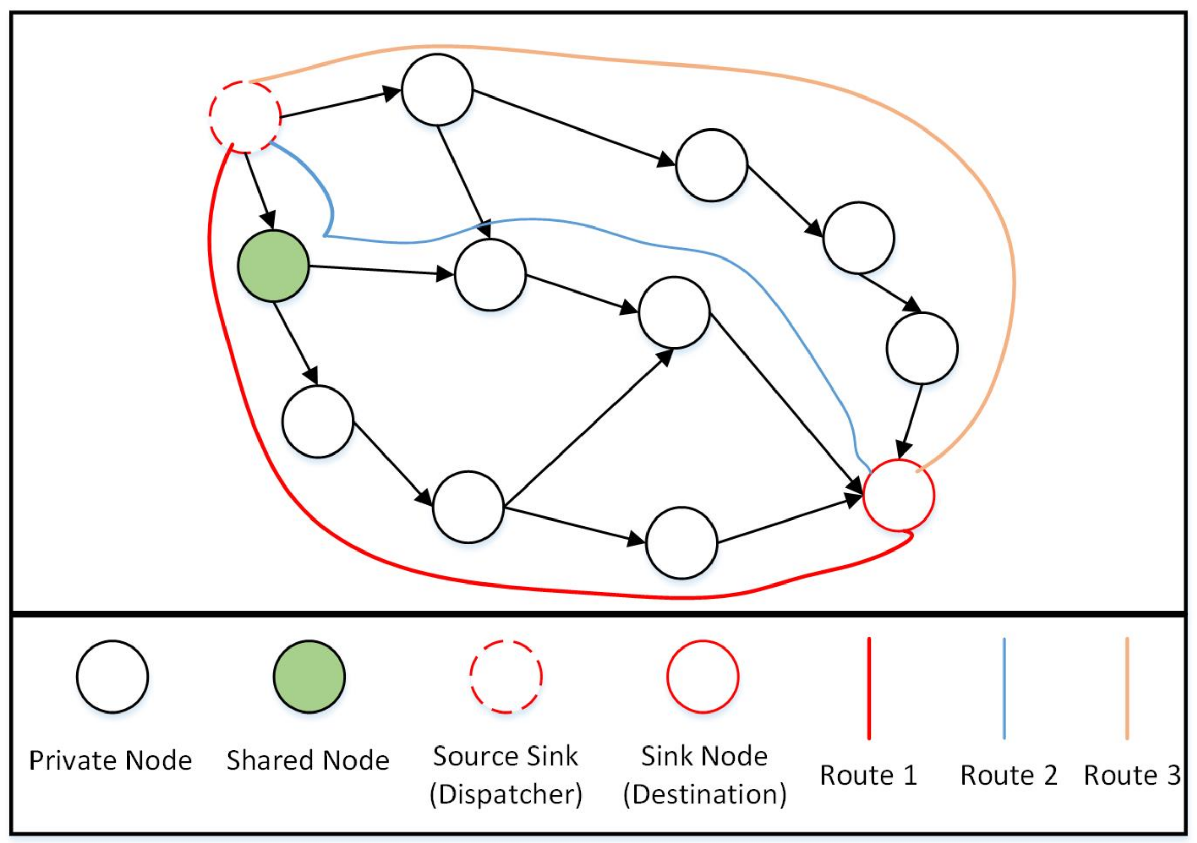
Figure 1 (GDMIP). All important elements are described, including itineraries, MAs, nodes, faulty nodes, and gathered data, and each component works its own certain function. It displays the arrangement of the related nodes with the specified route. The discovered shared nodes form the basis of the grouping. All network nodes are covered by the routes that are created. The sink node is in charge of allocating MAs to a specific group to gather data from. If a node is faulty in the group as a result of energy depletion during MA migration, the MA will pass that node in the group. The MA moves and collects data only from the groups that have been assigned to it. As an illustration, the path to the designated group is shown by the “itinerary” (orange line circles).
We employ a number of MAs to prevent reporting delays and to promote local interactions. We use a methodology similar to that described in [
36,
37] to determine the volume of sensory data that MAs should gather. In order to eliminate duplication and inconsistency, we use equivalent data aggregation techniques. A combination of sensory data effects and the ratio of an aggregation (“
”) is used.
is the quantity of the related sensor data for aggregation via the fusion factor
, with
having the actual quantity of related sensor data after the mobile agent receives data input from the source node
i.
Equation (
3) indicates that there is no data aggregation for the first node; also the value of
depends on the type of application being used.
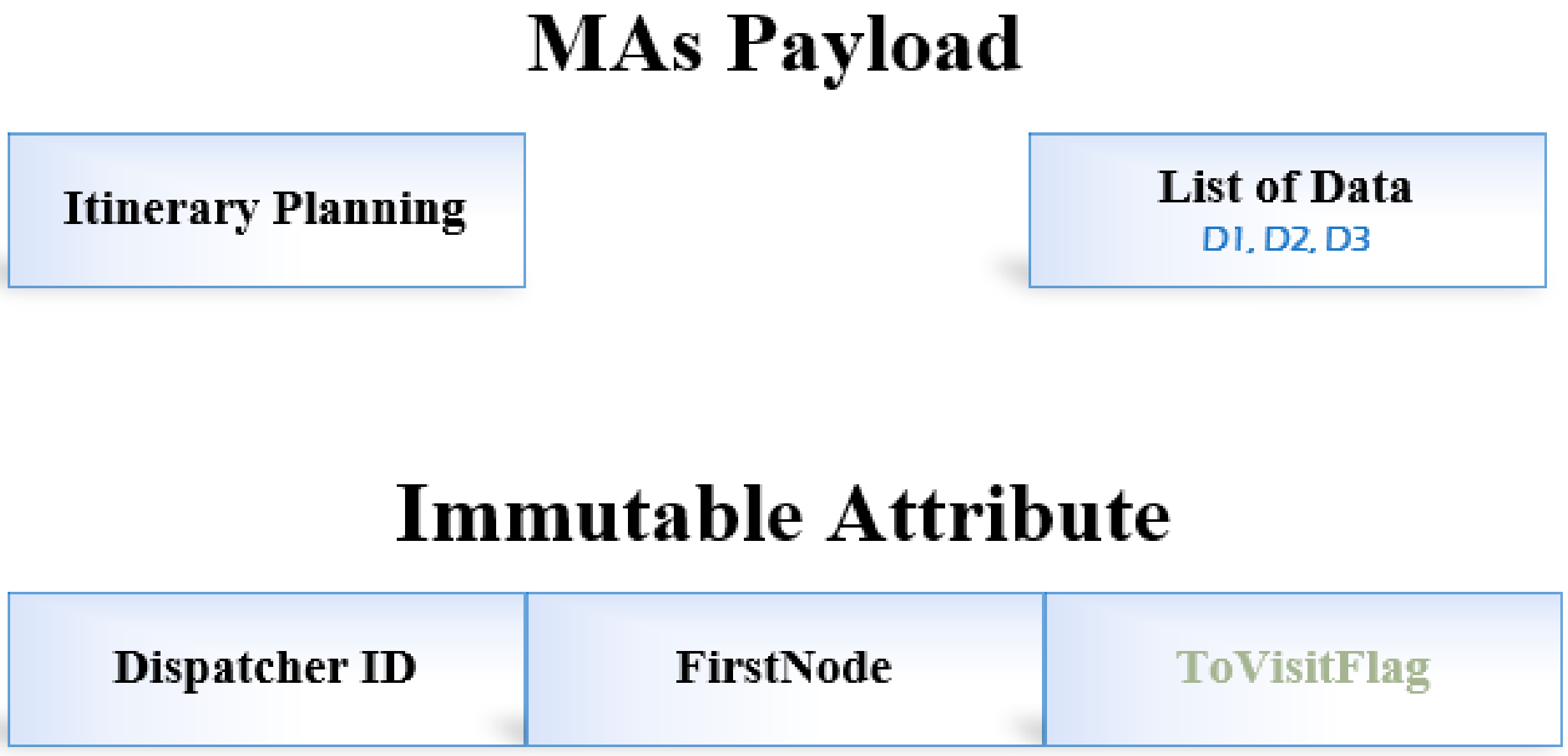
Figure 2 defines the proposed GDMIP data packet format. The initial data collection from the source node and the MA are represented by
FirstNode. We have established groups and routes. A group merely decides which nodes the MAs should collect data from. However, all computed routes are constructed with MAs migrating to every node on the route.
The agents’ payload consists of the messages Itinerary Planning and List of data. The node at the root that posts and generates the current mobile agent is recognized by the Dispatcher ID. ToVisitFlag is set up to check whether an agent visited the node or not. In order to gather data from the nodes along this specific path, routes are computed for the mobile agents to travel towards and visit each node and the group of nodes.
Additionally, we are of the view that sensors are expected to generate similar data when placed close together in order to simulate a real-world scenario. In light of this, agents may remove unnecessary data through fusion.
3.3. Intuitionistic Fuzzy Weighted Averaging (IFWA)
In multi-mobile agent itinerary planning algorithms, there are many factors involved. These factors are uncertain due to their nature. Fuzzy logic is similar to the natural decision-making process. It interacts with unclear and ambiguous knowledge. This is a simplified view of authentic situations, relying on stages of truth instead of the typical 1/0 or true/false as Boolean reasoning.
The phrase “fuzzy” refers to things that are unclear. We commonly meet circumstances in the real world in which we are unable to determine if such a condition is factually true, such as in this proposed approach, we are uncertain of the identified shortest route with the least number of nodes, in which fuzzy logic provides a highly useful variety of thinking. We may use this strategy to investigate the mistakes and inconsistencies in any circumstance. The Boolean paradigm represents 1.0 as the ultimate truth value and 0.0 as the ultimate false value. However, in the case of fuzzy systems, there is an intermediary value that is both partially true and most likely partially false. Lofti A. Zadeh invented fuzzy logic in his academic research “fuzzy sets (FSs)” in 1965 [
38].
A FS
F in the universe X can be characterised as a set of ordered pairs and formally depicted as
here,
represents the “membership function (MF)” whose range is
.
Fuzzy logics have various uses, such as altitude management of spaceships and rockets in the aviation industry. It has been utilised in automobile systems to manage speed and traffic, for decision-making assistance systems and security appraisal, for chemical process industries to manage the pH, drying, and chemical distillation processes, for natural language translation, and a variety of intense machine learning and artificial intelligence. Fuzzy logic is often employed in control design systems such as expert systems and in conjunction with Neural Networks because it simulates how humans make judgments, only much faster.
It is not always the case that the grade of non-membership of an object in an FS is equivalent to 1 minus the membership degree; this statement is not always accurate. As a result, intuitionistic fuzzy sets (IFSs) were proposed as a generalisation of FSs. The idea of defining IFSs as generalised FSs is intriguing and beneficial in a variety of application areas. Because it incorporates the “degree of belongingness”, “degree of non-belongingness”, and the hesitation margin, the information and semantic description of IFS become more significant, resourceful, and useful. A IFS
I in the universe X can be characterised as a set and formally depicted as,
here
represents the MF and
represents the non-MF; their ranges are
, with the constraint that the
X [
39].
Data aggregation is a key step in the selection process across many domains, including corporate, legislative, social, academic, technological, intellectual, and intelligent machines. Throughout the course of human history, comprehension of options has traditionally been regarded as a discrete or spoken amount. In the most recent decades, there has been a significant focus placed on the consolidation of various types of information. The efficiency of the AO, as well as their constraints, have been ingrained in the decision-making process. It should come as no surprise that AO incorporates a variety of standard procedures for combining a limited number of fuzzy numbers into a single fuzzy number.
Many elements are included in itinerary planning algorithms, including
grouping,
energy efficiency,
least number of nodes, and
avoiding excessive delays. Because these characteristics are ambiguous and unpredictable, we employ intuitionistic fuzzy numbers (IFNs) to better explain the information. In
Figure 3, as can be seen, there are three different routes (route 1, route 2, and route 3), and if we have a decision-maker (DM) to determine the best route based on the parameters (criteria) listed above, the DM assigns an IFN to each route based on its assessments of each criterion. We get a decision matrix after evaluating all paths and then use the “intuitionistic fuzzy weighted averaging (IFWA) operator” to aggregate the data [
40]. In IFWA operators, each criterion has a weight vector (WV) that specifies its relevance. An IFWA operator defines if we have a collection of IFNs given as
, where
. The IFWA operator is a mapping from
and is given as
where
is the WV of
with the constraint that the sum of WV is a unit.
A score function is used to define how one IFN is larger than another IFN. An IFN having a larger score value than another IFN , then is larger than . The score function is defined as .
A DM (or group of DMs) evaluates the three routes (route 1, route 2, and route 3) on the basis of the four criteria,
grouping,
energy efficiency,
least number of nodes, and
avoiding excessive delays, given in
Table 1. The WV of these criteria is
. Using the IFWA operator, we aggregate all IFNs for each route to obtain a single IFN for each route. Following that, we apply the scoring function to each aggregated IFN. If an aggregated IFN has a higher score value, the route associated with this IFN is a shorter route. As per the data given in
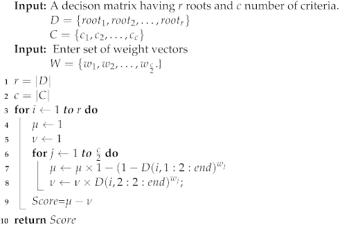
Table 1, the best route is “route 2”. Algorithm 2 is given for the working of an IFWA operator for selecting the optimum route solution.
| Algorithm 2: Working of IFWA operator to select optimal route |
![Sensors 22 08037 i002 Sensors 22 08037 i002]() |
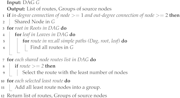
The algorithm related to the source grouping of the input nodes (Algorithm 3) is made explicitly for making a group of the input nodes for all of the MAs, networks, and practices, using G from Algorithm 1 as an input. It determines whether the node has two or more out-degree connections and at least one connection or more in-degree connections. This is a shared node as a result. Because of its multiple routes and status as a generating group construction piece, it plays a significant part in the network. It also serves as the primary hub for linking together the nodes in the DAG network. By figuring out the roots and leaves of the network, the specific algorithm learns and determines a set of various routes that cover all the related nodes and paths. Then, it determines every path between the leaves and roots. The source grouping method evaluates all routes to determine which has the fewest nodes based on Algorithm 2, which employs fuzzy aggregation operators, in order to determine the least route. A shared node is one that is a part of numerous routes, according to our definition. This indicates that many routes can be used to access common nodes. Following is how shared nodes between various routes will be distributed: (1) A collection of nodes that are exclusive to a given route are initially assigned to each route (these nodes are referred to as private nodes on the route) and (2) the group that currently has the fewest nodes among the associated routes will be given a shared node. Each created group specifies a collection of nodes from which the sent MAs can gather information.
| Algorithm 3: Source grouping of sensor nodes |
![Sensors 22 08037 i003 Sensors 22 08037 i003]() |
Figure 3 is an illustration of how the algorithms’ underlying ideas work. It displays a series of routes (in this example, routes 1, 2, and 3) that cover all nodes in the network, including shared and private nodes. Private nodes are those that are exclusive to a given route. Source nodes on several routes are referred to as shared nodes. In this example, there is just one shared node, and it is present on both routes 1 and 2. A group is also a collection of assigned shared nodes and private nodes in a specific route. The groups are created by assigning shared nodes to the group of a route that contains the fewest nodes overall. As an illustration, see
Figure 3. We assign the shared node to the group for route 2 since there are only two private nodes in the group for route 2, compared to the three private nodes in the group for route 1. Keep in mind that, in practice, the source sink (such as the dispatcher) and the sink node (such as the destination) may be the same (sink) node. Here, since the entire network is modelled as a DAG, it is effectively split into two nodes that each utilise a portion of the network’s links to source nodes.
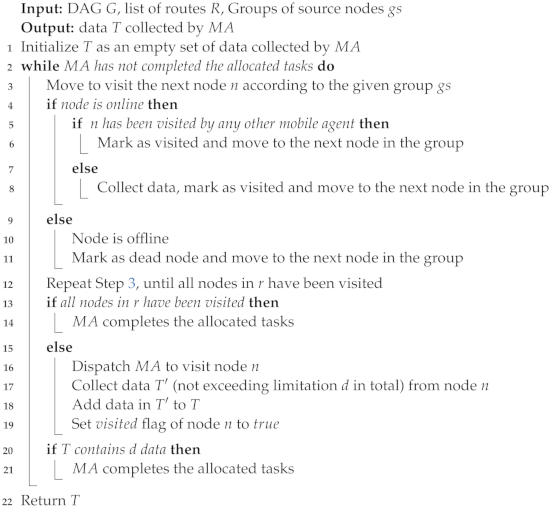
Mobile agents are dispatched to groups by Algorithm 4. The first inputs are a DAG ( (gs), which are provided using Algorithm 3. T will then be initialised with a blank bundle of data. In order to avoid having two agents take the same group, it starts by sending mobile agents to a certain group in . During the journey, each MA visits nodes on the specified group . First, it determines whether the node is accessible and online; if so, it gathers the information and marks the node as visited. Then, it checks if the node is offline; if so, it will be marked as dead, and the agent will move to the next node in the group. If the node’s flag is set to , it then moves on to visit the next node in the path. If not, the MA collects data up until its d data load and sets this node’s flag to . The MA completes the tasks assigned to it, then leaves by either travelling to every online node along the predetermined route or by gathering d data on the trip. The d data load threshold for each agent ensures that the agent buffer will not become overloaded with data in a single trip.
| Algorithm 4: Dispatch mobile agents MAs to collect data |
![Sensors 22 08037 i004 Sensors 22 08037 i004]() |

