

Generation of Prior Information in a Dual-Mode Microwave-Ultrasound Breast Imaging System


Abstract
1. Introduction
2. Materials and Methods
- Hold the breast in a known, fixed position and geometry while imposing minimal compression on the breast;
- Allow the US transducers to make direct contact with its surface, via slight compression or the use of an ultrasonic coupling gel;
- Have favourable acoustic properties: limited attenuation and limited reflection at the skin interface so that sufficient acoustic energy penetrates the breast; and
- Have favourable MW properties that allow MW energy to interrogate the breast while being easily incorporated in the MWI inversion model (as prior information).
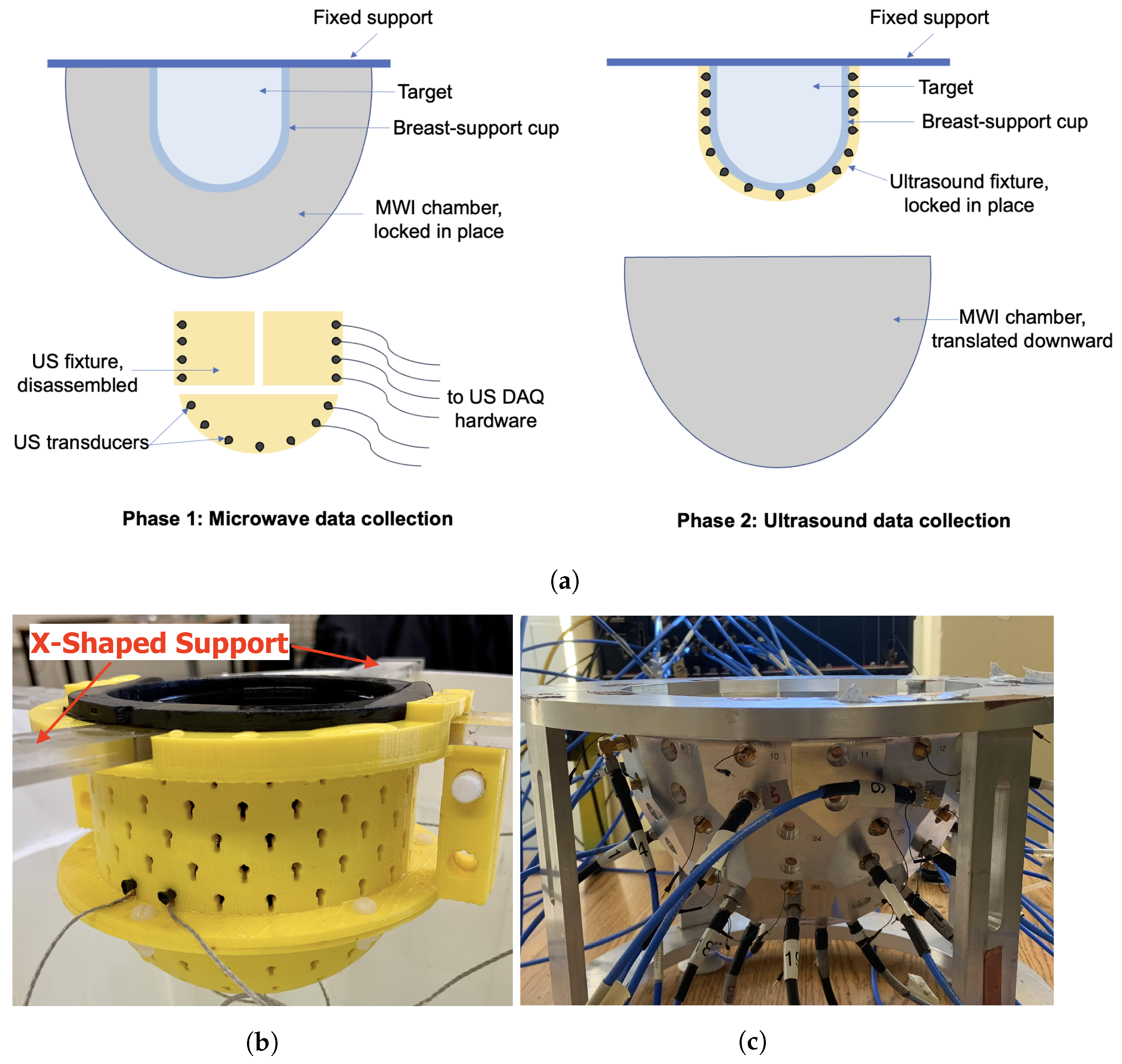
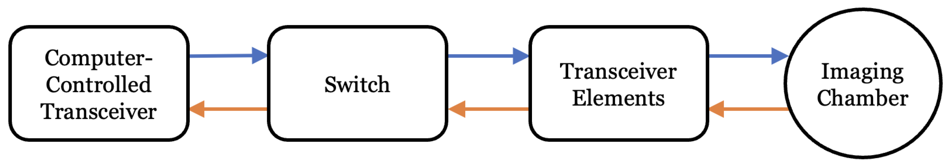
2.1. Ultrasound System Description
- An arbitrary waveform generator (AWG), comprised of four PC-based waveform generator cards (Signatec PXDAC4800), each with four channels. A pulsed sinusoid truncated after five periods was used to drive the US transducers at their observed resonant frequency of 1.4 MHz.
- A 32-channel digital oscilloscope, composed of four PC-based oscilloscope cards (GaGe Octopus 8387 CompuScope digitizer boards), each with 8 channels.
- A custom switch module that routes the transmitted signal from the waveform generator to the specified transducer and received signals from transducers to the corresponding oscilloscope channels.
- Custom MATLAB control software that coordinates the above components, including a graphical user interface (GUI).
- A novel, 3D-printed fixture that holds the 64 piezoelectric transducers in direct contact with the breast-support cup.
2.2. Microwave System Description
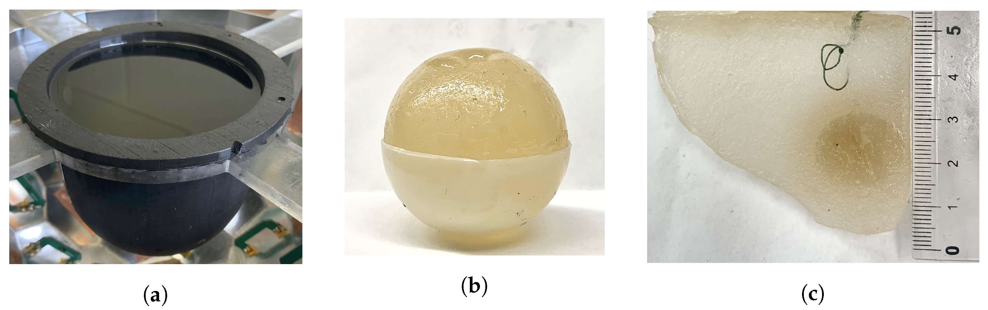
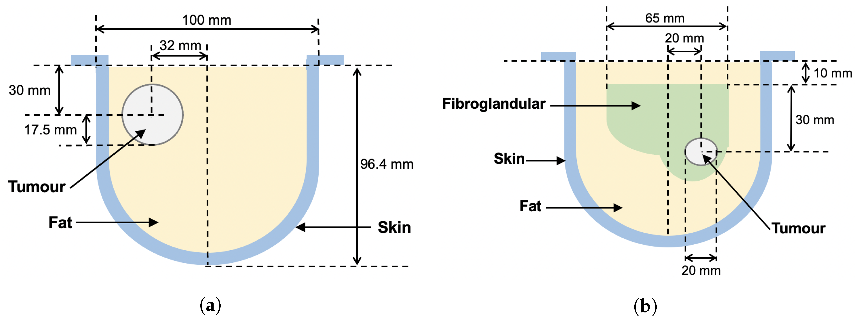
2.3. Breast Phantoms
2.4. US and MW Inversion Algorithms
2.5. Converting Sound Speed to Permittivity
- Segmented mapping—a k-means clustering algorithm was used to segment the sound speeds into two or more regions, e.g., fat and fibroglandular. Representative complex permittivity values for the tissues are assigned to the respective regions.
- Linear mapping—reconstructed sound speed values c are linearly re-scaled to ranges representative of real and imaginary parts of complex permittivity, using the following equations:
- Tissue-range mapping—a range of values of each physical property for each tissue type is set, based on the representative complex permittivity values. For each reconstructed value of speed, the distance from the mean of the corresponding tissue-dependent range is calculated. Complex permittivity is then assigned as the same relative distance from the mean for the given tissue type. This type of mapping is based on the tissue-dependent mapping technique described in [26].
3. Results
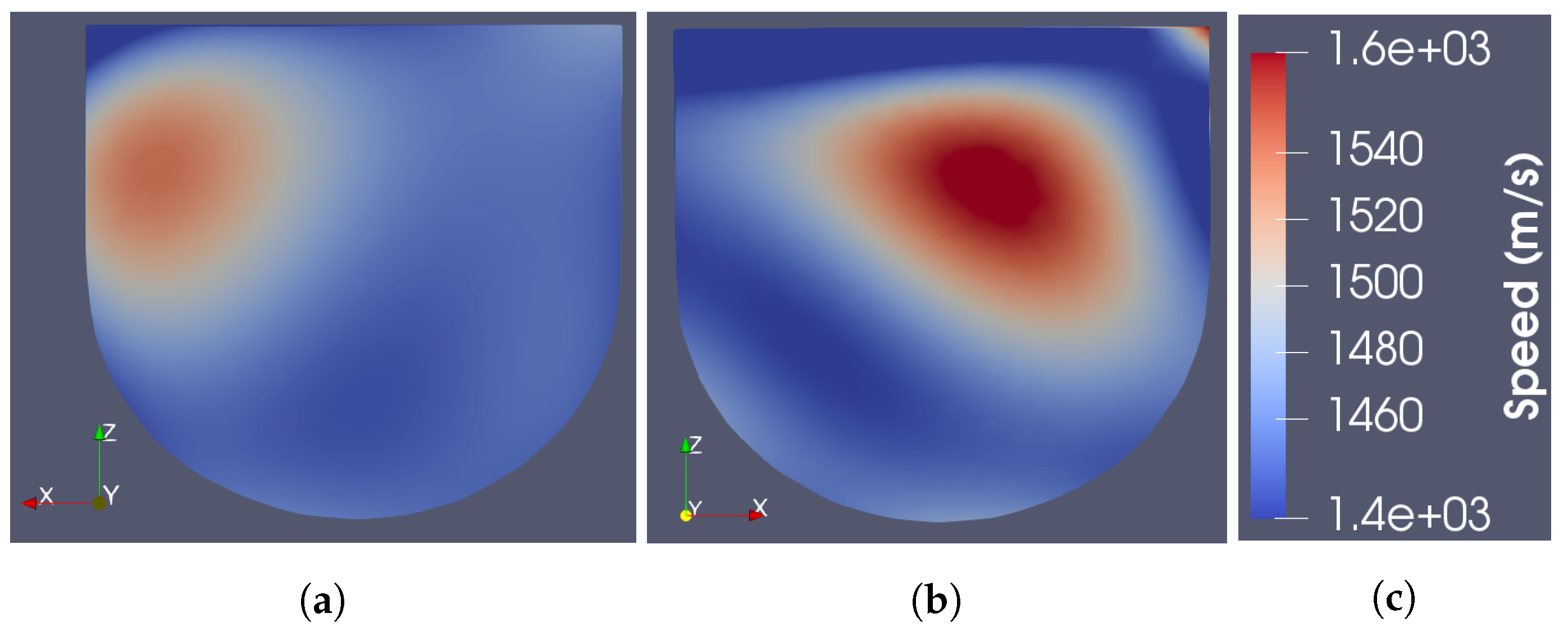
3.1. Ray-Based Ultrasound Speed Reconstruction
3.2. Sound Speed to Permittivity Mappings
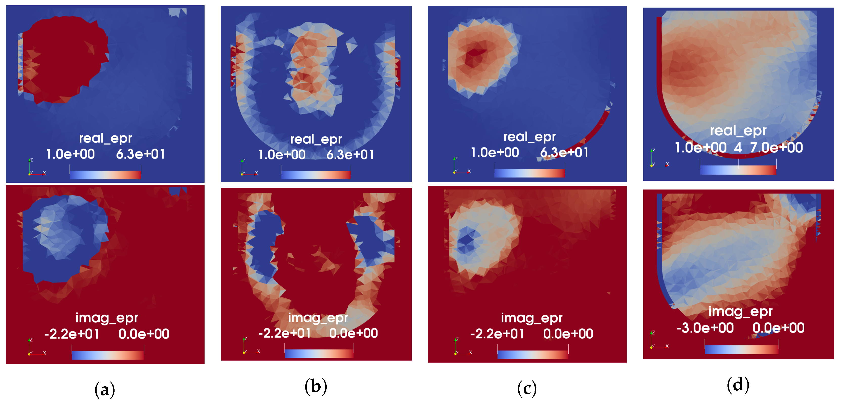
3.3. Microwave Reconstruction Results
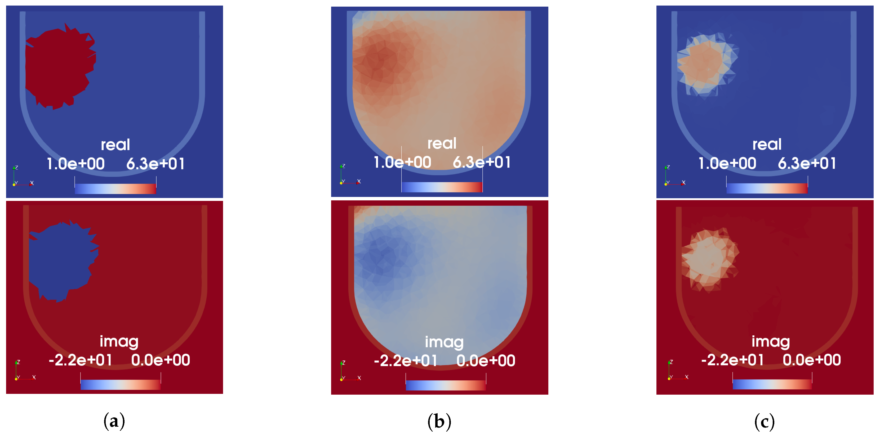
3.3.1. Phantom 1
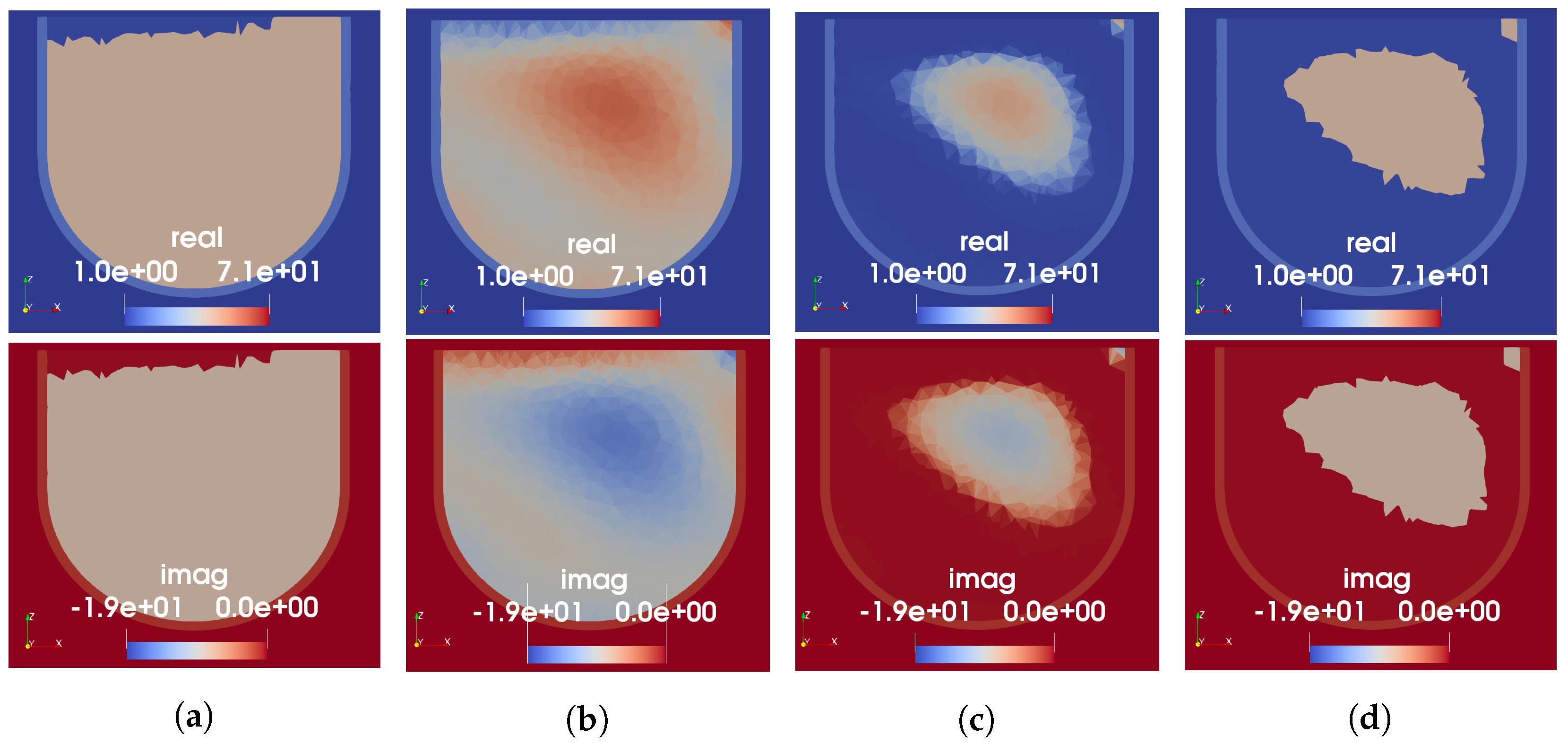
3.3.2. Phantom 2
4. Discussion
Author Contributions
Funding
Data Availability Statement
Conflicts of Interest
Abbreviations
| AIC | Akaike information criterion |
| AWG | arbitrary waveform generator |
| CCT | computer-controlled transceiver |
| CSI | contrast source inversion |
| FEM | finite element method |
| MER | modified energy ratio |
| MRI | magnetic resonance imaging |
| MWI | microwave imaging |
| MWR | microwave radar |
| OI | object of interest |
| PC | personal computer |
| TOF | time-of-flight |
| USI | ultrasound imaging |
| VNA | vector network analyzer |
References
- Bolomey, J.C. Crossed viewpoints on microwave-based imaging for medical diagnosis: From genesis to earliest clinical outcomes. In The World of Applied Electromagnetics; Springer: Berlin/Heidelberg, Germany, 2018; pp. 369–414. [Google Scholar]
- Moloney, B.M.; O’Loughlin, D.; Abd Elwahab, S.; Kerin, M.J. Breast cancer detection—A synopsis of conventional modalities and the potential role of microwave imaging. Diagnostics 2020, 10, 103. [Google Scholar] [CrossRef] [PubMed]
- Mojabi, P.; LoVetri, J. Experimental evaluation of composite tissue-type ultrasound and microwave imaging. IEEE J. Multiscale Multiphys. Comput. Tech. 2019, 4, 119–132. [Google Scholar] [CrossRef]
- O’Loughlin, D.; O’Halloran, M.; Moloney, B.M.; Glavin, M.; Jones, E.; Elahi, M.A. Microwave breast imaging: Clinical advances and remaining challenges. IEEE Trans. Biomed. Eng. 2018, 65, 2580–2590. [Google Scholar] [CrossRef] [PubMed]
- Boverman, G.; Davis, C.E.; Geimer, S.D.; Meaney, P.M. Image registration for microwave tomography of the breast using priors from nonsimultaneous previous magnetic resonance images. IEEE J. Electromagn. Microwaves Med. Biol. 2017, 2, 2–9. [Google Scholar] [CrossRef] [PubMed]
- Kurrant, D.; Fear, E. Regional estimation of the dielectric properties of inhomogeneous objects using near-field reflection data. Inverse Probl. 2012, 28, 075001. [Google Scholar] [CrossRef]
- Omer, M.; Mojabi, P.; Kurrant, D.; LoVetri, J.; Fear, E. Proof-of-concept of the incorporation of ultrasound-derived structural information into microwave radar imaging. IEEE J. Multiscale Multiphys. Comput. Tech. 2018, 3, 129–139. [Google Scholar] [CrossRef]
- Golnabi, A.H.; Meaney, P.M.; Geimer, S.D.; Paulsen, K.D. 3D microwave tomography using the soft prior regularization technique: Evaluation in anatomically realistic MRI-derived numerical breast phantoms. IEEE Trans. Biomed. Eng. 2019, 66, 2566–2575. [Google Scholar] [CrossRef]
- Jiang, H.; Li, C.; Pearlstone, D.; Fajardo, L.L. Ultrasound-guided microwave imaging of breast cancer: Tissue phantom and pilot clinical experiments. Med. Phys. 2005, 32, 2528–2535. [Google Scholar] [CrossRef]
- Bayat, N.; Mojabi, P.; Lovetri, J.; Mojabi, P. On Microwave Breast Imaging with Ultrasound Spatial Priors. In Proceedings of the 2020 XXXIIIrd General Assembly and Scientific Symposium of the International Union of Radio Science, Rome, Italy, 29 August–5 September 2020; pp. 1–4. [Google Scholar]
- Abdollahi, N.; Kurrant, D.; Mojabi, P.; Omer, M.; Fear, E.; LoVetri, J. Incorporation of Ultrasonic Prior Information for Improving Quantitative Microwave Imaging of Breast. IEEE J. Multiscale Multiphys. Comput. Tech. 2019, 4, 98–110. [Google Scholar] [CrossRef]
- Mojabi, P.; Abdollahi, N.; Omer, M.; Kurrant, D.; Jeffrey, I.; Fear, E.; LoVetri, J. Tissue-Type Imaging for Ultrasound-Prior Microwave Inversion. In Proceedings of the 2018 18th International Symposium on Antenna Technology and Applied Electromagnetics (ANTEM), Waterloo, ON, Canada, 19–22 August 2018; pp. 1–3. [Google Scholar] [CrossRef]
- Duric, N.; Littrup, P.; Poulo, L.; Babkin, A.; Pevzner, R.; Holsapple, E.; Rama, O.; Glide, C. Detection of breast cancer with ultrasound tomography: First results with the Computed Ultrasound Risk Evaluation (CURE) prototype. Med. Phys. 2007, 34, 773–785. [Google Scholar] [CrossRef]
- Duric, N.; Littrup, P.; Kuzmiak, C. Breast ultrasound tomography. In Breast Imaging; IntechOpen: London, UK, 2018; Chapter 6. [Google Scholar]
- Duric, N.; Sak, M.; Fan, S.; Pfeiffer, R.M.; Littrup, P.J.; Simon, M.S.; Gorski, D.H.; Ali, H.; Purrington, K.S.; Brem, R.F.; et al. Using whole breast ultrasound tomography to improve breast cancer risk assessment: A novel risk factor based on the quantitative tissue property of sound speed. J. Clin. Med. 2020, 9, 367. [Google Scholar] [CrossRef] [PubMed]
- Fogel, H. Development of a Dual-Mode Microwave-Ultrasound Breast Imaging System. Master’s Thesis, University of Manitoba, Winnipeg, MB, Canada, 2022. [Google Scholar]
- Khoshdel, V.; Ashraf, A.; LoVetri, J. Enhancement of multimodal microwave-ultrasound breast imaging using a deep-learning technique. Sensors 2019, 19, 4050. [Google Scholar] [CrossRef] [PubMed]
- Qin, Y.; Rodet, T.; Lambert, M.; Lesselier, D. Microwave breast imaging with prior ultrasound information. IEEE Open J. Antennas Propag. 2020, 1, 472–482. [Google Scholar] [CrossRef]
- Qin, Y.; Rodet, T.; Lambert, M.; Lesselier, D. Joint inversion of electromagnetic and acoustic data with edge-preserving regularization for breast imaging. IEEE Trans. Comput. Imaging 2021, 7, 349–360. [Google Scholar] [CrossRef]
- Hughson, M. Quantitative Transmission Tomography for Non-Destructive Imaging of Stored Grain and Biological Tissue. Master’s Thesis, University of Manitoba, Winnipeg, MB, Canada, 2021. [Google Scholar]
- Asefi, M.; Baran, A.; LoVetri, J. An experimental phantom study for air-based quasi-resonant microwave breast imaging. IEEE Trans. Microw. Theory Tech. 2019, 67, 3946–3954. [Google Scholar] [CrossRef]
- Nemez, K.; Baran, A.; Asefi, M.; LoVetri, J. Modeling error and calibration techniques for a faceted metallic chamber for magnetic field microwave imaging. IEEE Trans. Microw. Theory Tech. 2017, 65, 4347–4356. [Google Scholar] [CrossRef]
- Fogel, H.C.; Hughson, M.; Asefi, M.; Jeffrey, I.; LoVetri, J. An Integrated Microwave-Ultrasound Breast Imaging System: Initial Phantom Results. In Proceedings of the 2022 16th European Conference on Antennas and Propagation (EuCAP), Madrid, Spain, 27 March–1 April 2022; pp. 1–5. [Google Scholar]
- Garrett, J.D. Average Dielectric Property Analysis of Non-Uniform Structures: Tissue Phantom Development, Ultra-Wideband Transmission Measurements, and Signal Processing Techniques. Master’s Thesis, University of Calgary, Calgary, AB, Canada, 2014. [Google Scholar]
- Medina-Valdés, L.; Pérez-Liva, M.; Camacho, J.; Udías, J.; Herraiz, J.; González-Salido, N. Multi-modal ultrasound imaging for breast cancer detection. Phys. Procedia 2015, 63, 134–140. [Google Scholar] [CrossRef][Green Version]
- Kaye, C.; Jeffrey, I.; LoVetri, J. Improvement of multi-frequency microwave breast imaging through frequency cycling and tissue-dependent mapping. IEEE Trans. Antennas Propag. 2019, 67, 7087–7096. [Google Scholar] [CrossRef]
- Wong, J.; Han, L.; Bancroft, J.; Stewart, R. Automatic time-picking of first arrivals on noisy microseismic data. CSEG. 0 0.2 0.4 0.6 0.8 2009, 1, 1–4. [Google Scholar]
- Liu, K.Y.; Fear, E.C.; Potter, M.E. Antenna aperture localization for arrival time correction using first-break. Prog. Electromagn. Res. 2015, 62, 105–120. [Google Scholar] [CrossRef]
- St-Onge, A. Akaike information criterion applied to detecting first arrival times on microseismic data. In SEG Technical Program Expanded Abstracts 2011; Society of Exploration Geophysicists: Houston, TX, USA, 2011; pp. 1658–1662. [Google Scholar]
- Zakaria, A.; Gilmore, C.; LoVetri, J. Finite-element contrast source inversion method for microwave imaging. Inverse Probl. 2010, 26, 115010. [Google Scholar] [CrossRef]
- Amer Zakaria, I.J.; LoVetri, J.; Zakaria, A. Full-vectorial parallel finite-element contrast source inversion method. Prog. Electromagn. Res. 2013, 142, 463–483. [Google Scholar] [CrossRef]
- Kurrant, D.; Baran, A.; LoVetri, J.; Fear, E. Integrating prior information into microwave tomography Part 1: Impact of detail on image quality. Med. Phys. 2017, 44, 6461–6481. [Google Scholar] [CrossRef]
- Kurrant, D.; Fear, E.; Baran, A.; LoVetri, J. Integrating prior information into microwave tomography part 2: Impact of errors in prior information on microwave tomography image quality. Med. Phys. 2017, 44, 6482–6503. [Google Scholar] [CrossRef] [PubMed]
- Ostadrahimi, M.; Mojabi, P.; Gilmore, C.; Zakaria, A.; Noghanian, S.; Pistorius, S.; LoVetri, J. Analysis of incident field modeling and incident/scattered field calibration techniques in microwave tomography. IEEE Antennas Wirel. Propag. Lett. 2011, 10, 900–903. [Google Scholar] [CrossRef]
- Pérez-Liva, M.; Herraiz, J.; Udías, J.; Miller, E.; Cox, B.; Treeby, B. Time domain reconstruction of sound speed and attenuation in ultrasound computed tomography using full wave inversion. J. Acoust. Soc. Am. 2017, 141, 1595–1604. [Google Scholar] [CrossRef] [PubMed]
- Mojabi, P.; Hughson, M.; Khoshdel, V.; Jeffrey, I.; LoVetri, J. CNN for compressibility to permittivity mapping for combined ultrasound-microwave breast imaging. IEEE J. Multiscale Multiphys. Comput. Tech. 2021, 6, 62–72. [Google Scholar] [CrossRef]
- Bayat, N.; Mojabi, P. A Multiplicative Regularizer Augmented with Spatial Priors for Microwave Imaging. IEEE Trans. Antennas Propag. 2021, 69, 606–611. [Google Scholar] [CrossRef]
- Song, X.; Li, M.; Yang, F.; Xu, S.; Abubakar, A. Study on joint inversion algorithm of acoustic and electromagnetic data in biomedical imaging. IEEE J. Multiscale Multiphys. Comput. Tech. 2019, 4, 2–11. [Google Scholar] [CrossRef]
- Qin, Y.; Ran, P.; Rodet, T.; Lesselier, D. Breast imaging by convolutional neural networks from joint microwave and ultrasonic data. IEEE Trans. Antennas Propag. 2022, 70, 6265–6276. [Google Scholar] [CrossRef]


| Skin | Fat | Fibroglandular | Tumour | |
|---|---|---|---|---|
| Ingredients | graphite, | canola oil | 50 mL water | 100 mL water |
| urethane, | 50 mL 1-propanol | 1/8 tsp table salt | ||
| as given in [24] | 7 g gelatin | 7 g gelatin | ||
| 3 g agar | 3 g agar | |||
| 25 mL glycerin | 12.5 mL glycerin | |||
| Sound Speed | not measured | 1460 | 1595 | 1587 |
| , at 1.4 MHz | (1470) | (1515) | (1555) | |
| Relative Permittivity | 11-j1.3 | 2.9-j0.23 | 41-j8.4 | 63-j22, Phantom 1 |
| at 1 GHz | (35-j23) | (13-j10) | (33-j21) | 71-j19, Phantom 2 |
| (53-j19) |
| Tissue Type | Speed of Sound | ||
|---|---|---|---|
| Fat | 1430–1480 m/s | 2.5–3.5 | 0.15–0.25 |
| Transitional | 1481–1499 | 3.51–40.0 | 0.26–9.49 |
| Fibro | 1500–1559 | 40.01–52.5 | 9.50–12.50 |
| Tumour | 1560–1600 | 52.51–66.98 | 12.51–25.17 |
Publisher’s Note: MDPI stays neutral with regard to jurisdictional claims in published maps and institutional affiliations. |
© 2022 by the authors. Licensee MDPI, Basel, Switzerland. This article is an open access article distributed under the terms and conditions of the Creative Commons Attribution (CC BY) license (https://creativecommons.org/licenses/by/4.0/).
Share and Cite
Fogel, H.; Hughson, M.; Asefi, M.; Jeffrey, I.; LoVetri, J. Generation of Prior Information in a Dual-Mode Microwave-Ultrasound Breast Imaging System. Sensors 2022, 22, 7087. https://doi.org/10.3390/s22187087
Fogel H, Hughson M, Asefi M, Jeffrey I, LoVetri J. Generation of Prior Information in a Dual-Mode Microwave-Ultrasound Breast Imaging System. Sensors. 2022; 22(18):7087. https://doi.org/10.3390/s22187087
Chicago/Turabian StyleFogel, Hannah, Max Hughson, Mohammad Asefi, Ian Jeffrey, and Joe LoVetri. 2022. "Generation of Prior Information in a Dual-Mode Microwave-Ultrasound Breast Imaging System" Sensors 22, no. 18: 7087. https://doi.org/10.3390/s22187087
APA StyleFogel, H., Hughson, M., Asefi, M., Jeffrey, I., & LoVetri, J. (2022). Generation of Prior Information in a Dual-Mode Microwave-Ultrasound Breast Imaging System. Sensors, 22(18), 7087. https://doi.org/10.3390/s22187087