
Research Scenarios of Autonomous Vehicles, the Sensors and Measurement Systems Used in Experiments


Abstract
:1. Introduction
- -
- the number of systems to be checked at the same time is significant and the vehicles have a very complex structure;
- -
- the number of places where conducting research is possible is limited;
- -
- the trajectory of the tested vehicle may deviate significantly from the planned trajectory;
- -
- the legal regulation of AVs’ participation in traffic is inconsistent and unclear in different countries.
- -
- -
- the results of analysis focusing on cooperation between computer models and the systems of a real vehicle (technologies: HIL [8]);
- -
- -
- results of the validation of the human–machine interface through the interaction between the driver and the autonomous vehicle (technologies: DIL [7]);
- -
- research results of the vehicle at the proving grounds (closed area, dedicated track).
- -
- aim of the research;
- -
- test vehicle (platforms) data and the method of their preparation and configuration;
- -
- the use of the environment (surroundings, test track) in which the research will be conducted;
- -
- a set of elements and additional objects (complementary) which are required to be included in the research;
- -
- initial conditions and the planned course of the study (test sequence);
- -
- measuring equipment, its tasks, and method of use;
- -
- the quantities necessary to measure, the level of accuracy of the measurements, and the method of evaluation of the results;
- -
- safety procedures.
- -
- research tasks that currently dominate;
- -
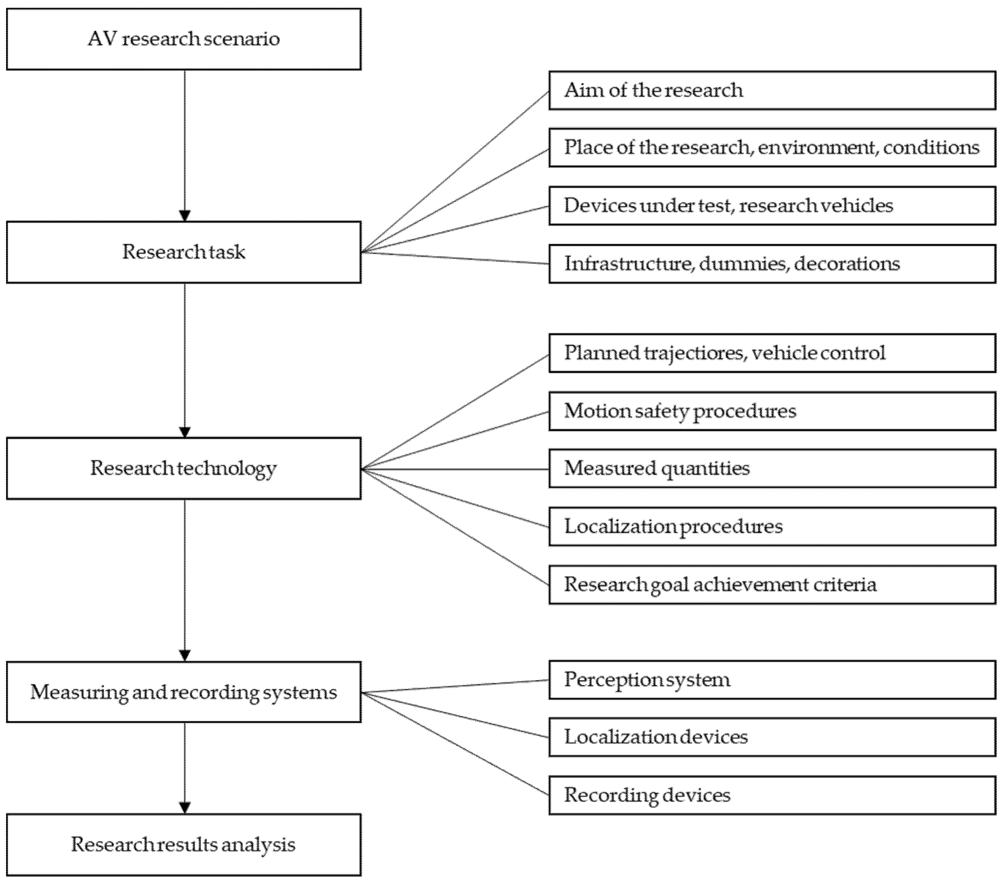
- elements to be included in the AV research scenario;
- -
- which normative documents are useful for organizing research;
- -
- what measuring and recording equipment is necessary.
2. Objectives and Scope of AV Research
- -
- recognition of the road situation;
- -
- planning a collision-free path;
- -
- current assessment of the real trajectory in relation to the planned path and making the necessary corrections.
- -
- navigation and digital maps of the driving area;
- -
- location of the vehicle in relation to the road infrastructure;
- -
- environment perception to recognize the situation around the vehicle.
3. Experimental Research Scenarios
3.1. Scope and Features of Typical AV Research
- -
- effectiveness of road line (lane boundary) detection;
- -
- the planning of a safe path for avoiding a slower moving vehicle.
3.2. Normative and Unified AV Test Procedures
- −
- EU [18];
- −
- −
- −
- −
- −
- −
3.3. Nonnormative Research Scenarios
- −
- −
- following the previous vehicle, e.g., as part of the movement within two circles [19];
- −
- −
- AV lane keeping:
- −
- −
- −
- 2D object detection, localization, and tracking:
- −
4. Technical Aspects of AV Research
4.1. Research Vehicles
4.2. Research Site
- −
- −
- −
- proving grounds containing an oval track (such as KATRI—Korea Apparel Testing and Research Institute) [30];
- −
- tracks used in car racing (Monza in Italy) [31];
- −
- fragments of road infrastructure excluded from public traffic which have been specially selected for conducting research according to specific scenarios [89];
- −
4.3. Infrastructure Elements and Other Objects
5. Measuring Systems, Sensors, and Measurement Ranges
5.1. Sensors Used for Perception and Control Systems
5.2. Sensors in Research Scenarios
5.2.1. Cameras
5.2.2. Radars
5.2.3. Lidars
5.2.4. Other Sensors
5.3. Measuring Equipment
- −
- waveforms related to the movement of the vehicle/obstacle (e.g., position and acceleration);
- −
- information and warning signals from the AV system interface;
- −
- course of the experiment (image from internal and external cameras installed on vehicle);
- −
- signals related to the vehicle control process.
6. Summary and Conclusions
- -
- normative and unified (e.g., SAE, Euro NCAP), which are applicable when testing vehicles and their systems in a repeatable manner (testing, inspection tests); unification of scenarios will make it possible to compare the different solutions used in AVs;
- -
- nonnormative, which were developed in various research centers; their course is adapted to the current needs of researchers. The research is of a cognitive nature and indicates the ways AVs can be improved and developed.
- -
- there is a lack of publications reporting experimental research related to AVs;
- -
- there is little information that can be obtained about the experimental research scenarios in the analyzed publications;
- -
- the lack of many legal regulations in the field of these studies means that a large part of the scenarios should be treated as individual ideas and solutions.
Author Contributions
Funding
Institutional Review Board Statement
Informed Consent Statement
Data Availability Statement
Conflicts of Interest
Abbreviations
| ACC | Active Cruise Control |
| ADAS | Advanced Driver Assistance Systems |
| ADMA | Automotive Dynamic Motion Analyzer |
| AEB–C2C | Autonomous Emergency Braking–Car-to-Car |
| AEB–VRU | Autonomous Emergency Braking–Vulnerable Road User |
| AEB | Autonomous Emergency Braking |
| AV | Autonomous/Automated Vehicle |
| CAN | Controller Area Network |
| CBFA | Car-to-Bicyclist Farside Adult |
| CBLA | Car-to-Bicyclist Longitudinal Adult |
| CBNA | Car-to-Bicyclist Nearside Adult |
| CBNAO | Car-to-Bicyclist Nearside Adult Obstructed |
| CCFtap | Car-to-Car Front Turn-Across-Path |
| CCRb | Car-to-Car Rear Braking |
| CCRm | Car-to-Car Rear Moving |
| CCRs | Car-to-Car Rear Stationary |
| CMOS | Complementary Metal-Oxide-Semiconductor |
| CPFA | Car-to-Pedestrian Farside Adult |
| CPLA | Car-to-Pedestrian Longitudinal Adult |
| CPNA | Car-to-Pedestrian Nearside Adult |
| CPNC | Car-to-Pedestrian Nearside Child |
| CPRA | Car-to-Pedestrian Reverse Adult |
| CPTA | Car-to-Pedestrian Turning Adult |
| DGNSS | Differential GNSS |
| DIL | Driver in the Loop |
| UNECE | United Nations Economic Commission for Europe |
| ELK | Emergency Lane Keeping |
| ESP | Electronics Stability Program |
| EU | European Union (European Parliament and the Council) |
| EURO NCAP | European New Car Assessment Programme |
| f | Frequency/refresh rate |
| FCW | Forward Collision Warning |
| FEB | Forward Emergency Braking |
| GLONASS | Global Navigation System |
| GNSS RTK | Global Navigation Satellite Systems Real Time Kinematic |
| GPS | Global Positioning System |
| H | Horizontal field of view |
| HIP | Hardware in the Loop |
| IIHS | Insurance Institute for Highway Safety |
| IMU | Inertial Measurement Unit |
| INS | Inertial Navigation System |
| ISO | International Organization for Standardization |
| KATRI | Korea Apparel Testing and Research Institute |
| Layers | number of scanning layers |
| LDW | Lane Departure Warning |
| LKA | Lane Keeping Assist |
| LSS | Lane Support Systems |
| MIL | Model in the Loop |
| NHTSA | National Highway Traffic Safety Administration |
| OXTS | Oxford Technical Solutions |
| P-AEB | Pedestrian-Autonomous Emergency Braking |
| R | Resolution |
| Range | maximum scanning distance |
| RGB | Red Green Blue |
| SAE | Society of Automotive Engineers |
| SAS | Speed Assist Systems |
| SIL | Software in the Loop |
| SLIF | Speed Limit Information Function |
| SLR | Single-Lens Reflex |
| UAV | Unmanned Aerial Vehicle |
| V | Vertical field of view |
| VIL | Vehicle in the Loop |
References
- J3016_201609; Taxonomy and Definitions for Terms Related to Driving Automation Systems for On-Road Motor Vehicles—SAE International. Available online: https://www.sae.org/standards/content/j3016_201609/ (accessed on 2 August 2022).
- J3016_201806; Taxonomy and Definitions for Terms Related to Driving Automation Systems for On-Road Motor Vehicles—SAE International. Available online: https://www.sae.org/standards/content/j3016_201806/ (accessed on 2 August 2022).
- Guerra, E. Planning for Cars That Drive Themselves: Metropolitan Planning Organizations, Regional Transportation Plans, and Autonomous Vehicles. J. Plan. Educ. Res. 2016, 36, 210–224. [Google Scholar] [CrossRef]
- Prochowski, L.; Ziubiński, M.; Szwajkowski, P.; Gidlewski, M.; Pusty, T.; Stańczyk, T.L. Impact of Control System Model Parameters on the Obstacle Avoidance by an Autonomous Car-Trailer Unit: Research Results. Energies 2021, 14, 2958. [Google Scholar] [CrossRef]
- Prochowski, L.; Ziubiński, M.; Szwajkowski, P.; Pusty, T.; Gidlewski, M. Experimental and Simulation Examination of the Impact of the Control Model on the Motion of a Motorcar with a Trailer in a Critical Situation. In Proceedings of the 15th International Conference Dynamical Systems-Theory and Applications DSTA, Łódź, Poland, 4 December 2019. [Google Scholar]
- Winner, H. Safety Assurance for Highly Automated Driving—The PEGASUS Approach. In Proceedings of the Automated Vehicle Symposium (AVS) 2017, San Francisco, CA, USA, 11–13 July 2017. [Google Scholar]
- Nabhan, M. Models and Algorithms for the Exploration of the Space of Scenarios: Toward the Validation of the Autonomous Vehicle. Ph.D. Thesis, Université Paris-Saclay, Paris, France, 2020. [Google Scholar]
- Pietruch, M.; Młyniec, A.; Wetula, A. An overview and review of testing methods for the verification and validation of ADAS, active safety systems, and autonomous driving. Min. Inform. Autom. Electr. Eng. 2020, 58, 19–27. [Google Scholar] [CrossRef]
- Duleba, S.; Tettamanti, T.; Nyerges, Á.; Szalay, Z. Ranking the Key Areas for Autonomous Proving Ground Development Using Pareto Analytic Hierarchy Process. IEEE Access 2021, 9, 51214–51230. [Google Scholar] [CrossRef]
- Aparicio, A. Badania Walidacyjne Samochodów Autonomicznych—Trudne Wyzwanie | Polska Izba Motoryzacji. Available online: https://pim.pl/badania-walidacyjne-samochodow-autonomicznych-trudne-wyzwanie/ (accessed on 2 August 2022).
- Morris, A.P.; Haworth, N.; Filtness, A.; Nguatem, D.-P.A.; Brown, L.; Rakotonirainy, A.; Glaser, S. Autonomous Vehicles and Vulnerable Road-Users—Important Considerations and Requirements Based on Crash Data from Two Countries. Behav. Sci. 2021, 11, 101. [Google Scholar] [CrossRef] [PubMed]
- Jurecki, R.S.; Stańczyk, T.L. A Methodology for Evaluating Driving Styles in Various Road Conditions. Energies 2021, 14, 3570. [Google Scholar] [CrossRef]
- Huang, W.; Wang, K.; Lv, Y.; Zhu, F. Autonomous Vehicles Testing Methods Review. In Proceedings of the 2016 IEEE 19th International Conference on Intelligent Transportation Systems (ITSC), Rio de Janeiro, Brazil, 1–4 November 2016; pp. 163–168. [Google Scholar]
- Németh, H.; Háry, A.; Szalay, Z.; Tihanyi, V.; Tóth, B. Proving Ground Test Scenarios in Mixed Virtual and Real Environment for Highly Automated Driving. In Mobilität in Zeiten der Veränderung: Technische und Betriebswirtschaftliche Aspekte; Proff, H., Ed.; Springer Fachmedien: Wiesbaden, Germany, 2019; pp. 199–210. ISBN 978-3-658-26107-8. [Google Scholar]
- Li, L.; Huang, W.-L.; Liu, Y.; Zheng, N.-N.; Wang, F.-Y. Intelligence Testing for Autonomous Vehicles: A New Approach. IEEE Trans. Intell. Veh. 2016, 1, 158–166. [Google Scholar] [CrossRef]
- J3045_201808; Truck and Bus Lane Departure Warning Systems Test Procedure and Minimum Performance Requirements—SAE International. Available online: https://www.sae.org/standards/content/j3045_201808 (accessed on 2 August 2022).
- Euro-Ncap-Aeb-C2c-Test-Protocol-V303.Pdf. Available online: https://cdn.euroncap.com/media/62794/euro-ncap-aeb-c2c-test-protocol-v303.pdf (accessed on 2 August 2022).
- Commission Delegated Regulation (EU) 2021/1958 of 23 June 2021 Supplementing Regulation (EU) 2019/2144 of the European Parliament and of the Council by Laying down Detailed Rules Concerning the Specific Test Procedures and Technical Requirements for the Type-Approval of Motor Vehicles with Regard to Their Intelligent Speed Assistance Systems and for the Type-Approval of Those Systems as Separate Technical Units and Amending Annex II to That Regulation (Text with EEA Relevance). Available online: http://data.europa.eu/eli/reg_del/2021/1958/oj (accessed on 2 August 2022).
- Spencer, M.; Jones, D.; Kraehling, M.; Stol, K. Trajectory Based Autonomous Vehicle Following Using a Robotic Driver. In Proceedings of the 2009 Australasian Conference on Robotics and Automation, ACRA 2009, Sydney, Australia, 2–4 December 2009. [Google Scholar]
- Ahmed, S.; Huda, M.N.; Rajbhandari, S.; Saha, C.; Elshaw, M.; Kanarachos, S. Pedestrian and Cyclist Detection and Intent Estimation for Autonomous Vehicles: A Survey. Appl. Sci. 2019, 9, 2335. [Google Scholar] [CrossRef]
- Ragesh, N.K.; Rajesh, R. Pedestrian Detection in Automotive Safety: Understanding State-of-the-Art. IEEE Access 2019, 7, 47864–47890. [Google Scholar] [CrossRef]
- Euro-Ncap-Sas-Test-Protocol-V20.pdf. Available online: https://cdn.euroncap.com/media/32290/euro-ncap-sas-test-protocol-v20.pdf (accessed on 2 August 2022).
- Negahbani, F.; Töre, O.B.; Güney, F.; Akgun, B. Frustum Fusion: Pseudo-LiDAR and LiDAR Fusion for 3D Detection 2021. arXiv 2021, arXiv:2111.04780. [Google Scholar]
- Kumar, G.A.; Lee, J.H.; Hwang, J.; Park, J.; Youn, S.H.; Kwon, S. LiDAR and Camera Fusion Approach for Object Distance Estimation in Self-Driving Vehicles. Symmetry 2020, 12, 324. [Google Scholar] [CrossRef] [Green Version]
- Meyer, G.P.; Charland, J.; Hegde, D.; Laddha, A.; Vallespi-Gonzalez, C. Sensor Fusion for Joint 3D Object Detection and Semantic Segmentation. In Proceedings of the IEEE/CVF Conference on Computer Vision and Pattern Recognition Workshops, Long Beach, CA, USA, 16–17 June 2019. [Google Scholar]
- Nkosi, M.P.; Hancke, G.P.; dos Santos, R.M.A. Autonomous Pedestrian Detection. In Proceedings of the AFRICON 2015, Addis Ababa, Ethiopia, 14–17 September 2015; pp. 1–5. [Google Scholar]
- Wu, C.-F.; Lin, C.-J.; Lee, C.-Y. Applying a Functional Neurofuzzy Network to Real-Time Lane Detection and Front-Vehicle Distance Measurement. Syst. Man Cybern. Part C Appl. Rev. IEEE Trans. 2012, 42, 577–589. [Google Scholar] [CrossRef]
- Euro-Ncap-Lss-Test-Protocol-V302.Pdf. Available online: https://cdn.euroncap.com/media/64973/euro-ncap-lss-test-protocol-v302.pdf (accessed on 2 August 2022).
- Gidlewski, M.; Jackowski, J.; Jemioł, L.; Żardecki, D. Sensitivity of a Vehicle Lane Change Control System to Disturbances and Measurement Signal Errors—Modeling and Numerical Investigations. Mech. Syst. Signal Processing 2021, 147, 107081. [Google Scholar] [CrossRef]
- Kang, C.M.; Lee, J.; Yi, S.G.; Jeon, S.J.; Son, Y.S.; Kim, W.; Lee, S.-H.; Chung, C.C. Lateral Control for Autonomous Lane Keeping System on Highways. In Proceedings of the 2015 15th International Conference on Control, Automation and Systems (ICCAS), Busan, Korea, 13–16 October 2015; pp. 1728–1733. [Google Scholar]
- Cudrano, P.; Mentasti, S.; Matteucci, M.; Bersani, M.; Arrigoni, S.; Cheli, F. Advances in Centerline Estimation for Autonomous Lateral Control. In Proceedings of the 2020 IEEE Intelligent Vehicles Symposium (IV), Las Vegas, NV, USA, 9 October–13 November 2020. [Google Scholar]
- Törő, O.; Bécsi, T.; Aradi, S. Design of Lane Keeping Algorithm of Autonomous Vehicle. Period. Polytech. Transp. Eng. 2016, 44, 60–68. [Google Scholar] [CrossRef]
- Li, X.; Sun, Z.; He, Z.; Zhu, Q.; Liu, D. A Practical Trajectory Planning Framework for Autonomous Ground Vehicles Driving in Urban Environments. In Proceedings of the 2015 IEEE Intelligent Vehicles Symposium (IV), Seoul, Korea, 28 June–1 July 2015; pp. 1160–1166. [Google Scholar]
- Hayashi, R.; Isogai, J.; Raksincharoensak, P.; Nagai, M. Autonomous Collision Avoidance System by Combined Control of Steering and Braking Using Geometrically Optimised Vehicular Trajectory. Veh. Syst. Dyn. 2012, 50, 151–168. [Google Scholar] [CrossRef]
- Favarò, F.M.; Nader, N.; Eurich, S.O.; Tripp, M.; Varadaraju, N. Examining Accident Reports Involving Autonomous Vehicles in California. PLoS ONE 2017, 12, e0184952. [Google Scholar] [CrossRef]
- Katzorke, N.; Moosmann, M.; Imdahl, R.; Lasi, H. A Method to Assess and Compare Proving Grounds in the Context of Automated Driving Systems. In Proceedings of the 2020 IEEE 23rd International Conference on Intelligent Transportation Systems (ITSC), Rhodes, Greece, 20–23 September 2020; pp. 1–6. [Google Scholar]
- Regulation No 130 of the Economic Commission for Europe of the United Nations (UN/ECE)—Uniform Provisions Concerning the Approval of Motor Vehicles with Regard to the Lane Departure Warning System (LDWS). Available online: http://data.europa.eu/eli/reg/2014/130/oj (accessed on 2 August 2022).
- UN Regulation No 152—Uniform Provisions Concerning the Approval of Motor Vehicles with Regard to the Advanced Emergency Braking System (AEBS) for M1 and N1 Vehicles [2020/1597]. Available online: https://op.europa.eu/en/publication-detail/-/publication/fc2d3589-1a7c-11eb-b57e-01aa75ed71a1 (accessed on 2 August 2022).
- UN Regulation No 157—Uniform Provisions Concerning the Approval of Vehicles with Regards to Automated Lane Keeping Systems [2021/389]. Available online: https://op.europa.eu/en/publication-detail/-/publication/36fd3041-807a-11eb-9ac9-01aa75ed71a1 (accessed on 2 August 2022).
- ISO 17361:2017. Available online: https://www.iso.org/cms/render/live/en/sites/isoorg/contents/data/standard/07/23/72349.html (accessed on 2 August 2022).
- ISO 15623:2013. Available online: https://www.iso.org/cms/render/live/en/sites/isoorg/contents/data/standard/05/66/56655.html (accessed on 2 August 2022).
- ISO 21202:2020. Available online: https://www.iso.org/cms/render/live/en/sites/isoorg/contents/data/standard/07/00/70072.html (accessed on 2 August 2022).
- Euro-Ncap-Aeb-Vru-Test-Protocol-V304.Pdf. Available online: https://cdn.euroncap.com/media/62795/euro-ncap-aeb-vru-test-protocol-v304.pdf (accessed on 2 August 2022).
- Forkenbrock, G.; Hoover, R.L.; Gerdus, E.; Buskirk, T.V.; Heitz, M. Blind Spot Monitoring in Light Vehicles—System Performance. Available online: https://www.nhtsa.gov/sites/nhtsa.gov/files/812045_blind-spot-monitoring-in-light-vehicles-system-performance.pdf (accessed on 2 August 2022).
- Howe, G.; Xu, G.; Hoover, D.; Elsasser, D.; Barickman, F. Commercial Connected Vehicle Test Procedure Development and Test Results—Blind Spot Warning/Lane Change Warning. 2016. Available online: https://www.nhtsa.gov/sites/nhtsa.gov/files/documents/812317_connectedveh.pdf (accessed on 2 August 2022).
- Thorn, E.; Kimmel, S.; Chaka, M. A Framework for Automated Driving System Testable Cases and Scenarios. 2018. Available online: https://www.nhtsa.gov/sites/nhtsa.gov/files/documents/13882-automateddrivingsystems_092618_v1a_tag.pdf (accessed on 2 August 2022).
- J2808_201701; Lane Departure Warning Systems: Information for the Human Interface—SAE International. Available online: https://www.sae.org/standards/content/j2808_201701 (accessed on 2 August 2022).
- Test_protocol_aeb.Pdf. Available online: https://www.iihs.org/media/a582abfb-7691-4805-81aa-16bbdf622992/REo1sA/Ratings/Protocols/current/test_protocol_aeb.pdf (accessed on 2 August 2022).
- Test_protocol_pedestrian_aeb.Pdf. Available online: https://www.iihs.org/media/f6a24355-fe4b-4d71-bd19-0aab8b39aa7e/TfEBAA/Ratings/Protocols/current/test_protocol_pedestrian_aeb.pdf (accessed on 2 August 2022).
- Paula, D.; Böhm, K.; Kubjatko, T.; Schweiger, H.-G. Autonomous Emergency Braking (AEB) Experiments for Traffic Accident Reconstruction. In Proceedings of the 25th International Scientific Conference Transport Means, Kaunas, Lithuania, 6–8 October 2021. [Google Scholar]
- Böhm, K.; Paula, D.; Geidl, B.; Graßl, L.; Kubjatko, T.; Schweiger, H.-G. Reliability and Performance of the AEB System of a Tesla Model X under Different Conditions. In Proceedings of the 29th Annual Congress of the European Association for Accident Research, Haifa, Israel, 6–7 October 2021. [Google Scholar]
- ISO 19237:2017. Available online: https://www.iso.org/cms/render/live/en/sites/isoorg/contents/data/standard/06/41/64111.html (accessed on 2 August 2022).
- ISO 22078:2020. Available online: https://www.iso.org/cms/render/live/en/sites/isoorg/contents/data/standard/07/25/72508.html (accessed on 2 August 2022).
- ISO 22839:2013. Available online: https://www.iso.org/cms/render/live/en/sites/isoorg/contents/data/standard/04/53/45339.html (accessed on 2 August 2022).
- Ivanov, A.M.; Shadrin, S.S.; Kristalniy, S.R.; Popov, N.V. Possible Scenarios of Autonomous Vehicles’ Testing in Russia. IOP Conf. Ser. Mater. Sci. Eng. 2019, 534, 012001. [Google Scholar] [CrossRef]
- Ivanov, A.M.; Kristalniy, S.R.; Popov, N.V.; Toporkov, M.A.; Isakova, M.I. New Testing Methods of Automatic Emergency Braking Systems and the Experience of Their Application. IOP Conf. Ser. Mater. Sci. Eng. 2018, 386, 012019. [Google Scholar] [CrossRef]
- Ivanov, A.M.; Shadrin, S.S. System of Requirements and Testing Procedures for Autonomous Driving Technologies. IOP Conf. Ser. Mater. Sci. Eng. 2020, 819, 012016. [Google Scholar] [CrossRef]
- Ivanov, A.; Kristalniy, S.; Popov, N. Russian National Non-Commercial Vehicle Safety Rating System RuNCAP. IOP Conf. Ser. Mater. Sci. Eng. 2021, 1159, 012088. [Google Scholar] [CrossRef]
- ISO 11270:2014. Available online: https://www.iso.org/cms/render/live/en/sites/isoorg/contents/data/standard/05/03/50347.html (accessed on 2 August 2022).
- ISO 17387:2008. Available online: https://www.iso.org/cms/render/live/en/sites/isoorg/contents/data/standard/04/36/43654.html (accessed on 2 August 2022).
- ISO 11067:2015. Available online: https://www.iso.org/cms/render/live/en/sites/isoorg/contents/data/standard/05/00/50091.html (accessed on 2 August 2022).
- ISO 15622:2018. Available online: https://www.iso.org/cms/render/live/en/sites/isoorg/contents/data/standard/07/15/71515.html (accessed on 2 August 2022).
- ISO 22178:2009. Available online: https://www.iso.org/cms/render/live/en/sites/isoorg/contents/data/standard/04/07/40752.html (accessed on 2 August 2022).
- ISO 16787:2017. Available online: https://www.iso.org/cms/render/live/en/sites/isoorg/contents/data/standard/07/37/73768.html (accessed on 2 August 2022).
- ISO 17386:2010. Available online: https://www.iso.org/cms/render/live/en/sites/isoorg/contents/data/standard/05/14/51448.html (accessed on 2 August 2022).
- ISO 22737:2021. Available online: https://www.iso.org/cms/render/live/en/sites/isoorg/contents/data/standard/07/37/73767.html (accessed on 2 August 2022).
- Bruno, D.; Peres Nunes Matias, L.; Amaro, J.; Osório, F.S.; Wolf, D. Computer Vision System with 2D and 3D Data Fusion for Detection of Possible Auxiliaries Routes in Stretches of Interdicted Roads. In Proceedings of the 52nd Hawaii International Conference on System Sciences HICSS, Grand Wailea, Maui, HI, USA, 8–11 January 2019; ISBN 978-0-9981331-2-6. [Google Scholar]
- Madawy, K.E.; Rashed, H.; Sallab, A.E.; Nasr, O.; Kamel, H.; Yogamani, S. RGB and LiDAR Fusion Based 3D Semantic Segmentation for Autonomous Driving. In Proceedings of the 2019 IEEE Intelligent Transportation Systems Conference (ITSC), Auckland, New Zealand, 27–30 October 2019. [Google Scholar]
- Yang, Z.; Li, J.; Li, H. Real-Time Pedestrian Detection for Autonomous Driving. In Proceedings of the 2018 International Conference on Intelligent Autonomous Systems (ICoIAS), Singapore, 1–3 March 2018; pp. 9–13. [Google Scholar]
- Wu, B.F.; Lin, C.-T.; Chen, C.-J. Real-Time Lane and Vehicle Detection Based on A Single Camera Model. Int. J. Comput. Appl. 2010, 32, 149–159. [Google Scholar] [CrossRef]
- Matsubayashi, K.; Yamad, Y.; Iyoda, M.; Koike, S.; Kawasaki, T.; Tokuda, M. Development of Rear Pre-Crash Safety System for Rear-End Collisions. In Proceedings of the 20th International Technical Conference on the Enhanced Safety of Vehicles (ESV), Lyon, France, 18–21 June 2007. [Google Scholar]
- Jansson, J. Collision Avoidance Theory: With Application to Automotive Collision Mitigation. Ph.D. Thesis, Linköping studies in science and technology Dissertations. Linköping University Electronic Press, Sweden, Switzerland, 2005. [Google Scholar]
- Janai, J.; Güney, F.; Behl, A.; Geiger, A. Computer Vision for Autonomous Vehicles: Problems, Datasets and State of the Art. Found. Trends Comput. Graph. Vis. 2017, 12, 1–308. [Google Scholar] [CrossRef]
- Aryal, M. Object Detection, Classification, and Tracking for Autonomous Vehicle. Master’s Thesis, Grand Valley States University, Grand Rapids, MI, USA, 2018. [Google Scholar]
- Blachut, K.; Danilowicz, M.; Szolc, H.; Wasala, M.; Kryjak, T.; Komorkiewicz, M. Automotive Perception System Evaluation with Reference Data from a UAV’s Camera Using ArUco Markers and DCNN. J. Sign Process Syst. 2022, 94, 675–692. [Google Scholar] [CrossRef]
- Gao, F.; Li, C.; Zhang, B. A Dynamic Clustering Algorithm for Lidar Obstacle Detection of Autonomous Driving System. IEEE Sens. J. 2021, 21, 25922–25930. [Google Scholar] [CrossRef]
- Lim, B.; Woo, T.; Kim, H. Integration of Vehicle Detection and Distance Estimation Using Stereo Vision for Real-Time AEB System. In Proceedings of the 3rd International Conference on Vehicle Technology and Intelligent Transport Systems—VEHITS, Porto, Portugal, 22–24 April 2017; pp. 211–216, ISBN 978-989-758-242-4. [Google Scholar] [CrossRef]
- Song, W.; Zou, S.; Tian, Y.; Fong, S.; Cho, K. Classifying 3D Objects in LiDAR Point Clouds with a Back-Propagation Neural Network. Hum. Cent. Comput. Inf. Sci. 2018, 8, 29. [Google Scholar] [CrossRef]
- Shilo, A. Detection and Tracking of Unknown Objects on the Road Based on Sparse LiDAR Data for Heavy Duty Vehicles. Master’s Thesis, KTH School of Electrical Engineering and Computer Science (EECS), Stockholm, Sweden, 2018. Available online: http://www.diva-portal.org/smash/get/diva2:1256042/FULLTEXT01.pdf (accessed on 2 August 2022).
- Vincke, B.; Rodriguez Florez, S.; Aubert, P. An Open-Source Scale Model Platform for Teaching Autonomous Vehicle Technologies. Sensors 2021, 21, 3850. [Google Scholar] [CrossRef]
- Scheffe, P.; Maczijewski, J.; Kloock, M.; Kampmann, A.; Derks, A.; Kowalewski, S.; Alrifaee, B. Networked and Autonomous Model-Scale Vehicles for Experiments in Research and Education. This Research Is Supported by the Deutsche Forschungsgemein-Schaft (German Research Foundation) within the Priority Program SPP 1835 “Cooperative Interacting Automobiles” (Grant Number: KO 1430/17-1) and the Post Graduate Program GRK 1856 “Integrated Energy Supply Modules for Roadbound E-Mobility”. IFAC-PapersOnLine 2020, 53, 17332–17337. [Google Scholar] [CrossRef]
- Lapapong, S.; Gupta, V.; Callejas, E.; Brennan, S. Fidelity of Using Scaled Vehicles for Chassis Dynamic Studies. Veh. Syst. Dyn. 2009, 47, 1401–1437. [Google Scholar] [CrossRef]
- Liburdi, A. Development of a Scale Vehicle Dynamics Test Bed. Master’s Thesis, University of Windsor, Windsor, ON, Canada, 2010. Available online: https://scholar.uwindsor.ca/etd/195/ (accessed on 2 August 2022).
- Park, Y.; Kim, B.; Ahn, C. Scaled Experiment with Dimensional Analysis for Vehicle Lateral Dynamics Maneuver. In Proceedings of the Advances in Dynamics of Vehicles on Roads and Tracks; Klomp, M., Bruzelius, F., Nielsen, J., Hillemyr, A., Eds.; Springer International Publishing: Cham, Switzerland, 2020; pp. 1288–1294. [Google Scholar]
- Szalay, Z.; Tettamanti, T.; Esztergár-Kiss, D.; Varga, I.; Bartolini, C. Development of a Test Track for Driverless Cars: Vehicle Design, Track Configuration, and Liability Considerations. Period. Polytech. Transp. Eng. 2018, 46, 29–35. [Google Scholar] [CrossRef]
- Katzorke, N. Proving Ground Requirements for Automated Vehicle Testing. In Proceedings of the ADAS & Autonomous Vehicle Technology Conference, San Jose, CA, USA, 7–8 September 2022. [Google Scholar] [CrossRef]
- Chen, R.; Arief, M.; Zhang, W.; Zhao, D. How to Evaluate Proving Grounds for Self-Driving? A Quantitative Approach. IEEE Trans. Intell. Transp. Syst. 2021, 22, 5737–5748. [Google Scholar] [CrossRef]
- Chen, R.; Arief, M.; Zhao, D. An “Xcity” Optimization Approach to Designing Proving Grounds for Connected and Autonomous Vehicles. arXiv 2018, arXiv:1808.03089. [Google Scholar]
- Fremont, D.J.; Kim, E.; Pant, Y.V.; Seshia, S.A.; Acharya, A.; Bruso, X.; Wells, P.; Lemke, S.; Lu, Q.; Mehta, S. Formal Scenario-Based Testing of Autonomous Vehicles: From Simulation to the Real World. In Proceedings of the 2020 IEEE 23rd International Conference on Intelligent Transportation Systems (ITSC), Rhodes, Greece, 20–23 September 2020; pp. 1–8. [Google Scholar]
- Xiong, L.; Fu, Z.; Zeng, D.; Leng, B. An Optimized Trajectory Planner and Motion Controller Framework for Autonomous Driving in Unstructured Environments. Sensors 2021, 21, 4409. [Google Scholar] [CrossRef]
- Yang, S.M.; Lin, Y.A. Development of an Improved Rapidly Exploring Random Trees Algorithm for Static Obstacle Avoidance in Autonomous Vehicles. Sensors 2021, 21, 2244. [Google Scholar] [CrossRef] [PubMed]
- Szalay, Z. Structure and Architecture Problems of Autonomous Road Vehicle Testing and Validation. In Proceedings of the 15th Mini Conference on Vehicle System Dynamics, Identification and Anomalies-VSDIA, Budapest, Hungary, 7–9 November 2016; Volume 24, pp. 229–236, ISBN 978-963-313-266-1. [Google Scholar]
- Aparicio, A.; Boltshauser, S.; Lesemann, M.; Jacobson, J.; Eriksson, H.; Herard, J. Status of Test Methods for Active Safety Systems; SAE International: Warrendale, PA, USA, 2012. [Google Scholar]
- Aparicio, A.; Lesemann, M.; Eriksson, H. Status of Test Methods for Autonomous Emergency Braking Systems—Results from the Active Test Project. In Proceedings of the SAE 2013 World Congress and Exhibition, Detroit, MI, USA, 16–18 April 2013. [Google Scholar]
- Christiansen, P.H. TractorEYE: Vision-Based Real-Time Detection for Autonomous Vehicles in Agriculture; Aarhus University Library Scholarly: Aarhus, Denmark, 7 November 2018; ISBN 978-87-7507-426-6. [Google Scholar] [CrossRef]
- Haris, M.; Hou, J. Obstacle Detection and Safely Navigate the Autonomous Vehicle from Unexpected Obstacles on the Driving Lane. Sensors 2020, 20, 4719. [Google Scholar] [CrossRef] [PubMed]
- Bae, H.; Lee, G.; Yang, J.; Shin, G.; Choi, G.; Lim, Y. Estimation of the Closest In-Path Vehicle by Low-Channel LiDAR and Camera Sensor Fusion for Autonomous Vehicles. Sensors 2021, 21, 3124. [Google Scholar] [CrossRef]
- Regulation (EU) 2019/2144 of the European Parliament and of the Council of 27 November 2019 on Type-Approval Requirements for Motor Vehicles and Their Trailers, and Systems, Components and Separate Technical Units Intended for Such Vehicles, as Regards Their General Safety and the Protection of Vehicle Occupants and Vulnerable Road Users, Amending Regulation (EU) 2018/858 of the European Parliament and of the Council and Repealing Regulations (EC) No 78/2009, (EC) No 79/2009 and (EC) No 661/2009 of the European Parliament and of the Council and Commission Regulations (EC) No 631/2009, (EU) No 406/2010, (EU) No 672/2010, (EU) No 1003/2010, (EU) No 1005/2010, (EU) No 1008/2010, (EU) No 1009/2010, (EU) No 19/2011, (EU) No 109/2011, (EU) No 458/2011, (EU) No 65/2012, (EU) No 130/2012, (EU) No 347/2012, (EU) No 351/2012, (EU) No 1230/2012 and (EU) 2015/166 (Text with EEA Relevance). Available online: http://data.europa.eu/eli/reg/2019/2144/oj (accessed on 2 August 2022).


| Task and aim of the research | The research task in the described scenarios is automated driving along a detected road lane on a curvilinear track. The aim of the research is to keep the vehicle in the road lane. The lane is maintained by controlling the steered wheels or additionally by selecting the driving velocity. |
| Research object | The research used passenger cars equipped with systems enabling autonomous driving [30,31] or a go-kart which performs AV functions [32]. For this purpose, elements of the perception system, path planning, and the steering wheel control system were used. In this research, the path planning system determines the reference trajectory along the center line of the road lane. |
| Research site/environment | The location used for this research is specialized research tracks. KATRI [30], Aci-Sara Lainate and the Monza Eni Circuit [31] tracks were used. They create road infrastructure for safe and repeatable research in the form of closed loops. In [32], the perception system used track elements in the form of road signs to select driving velocity. |
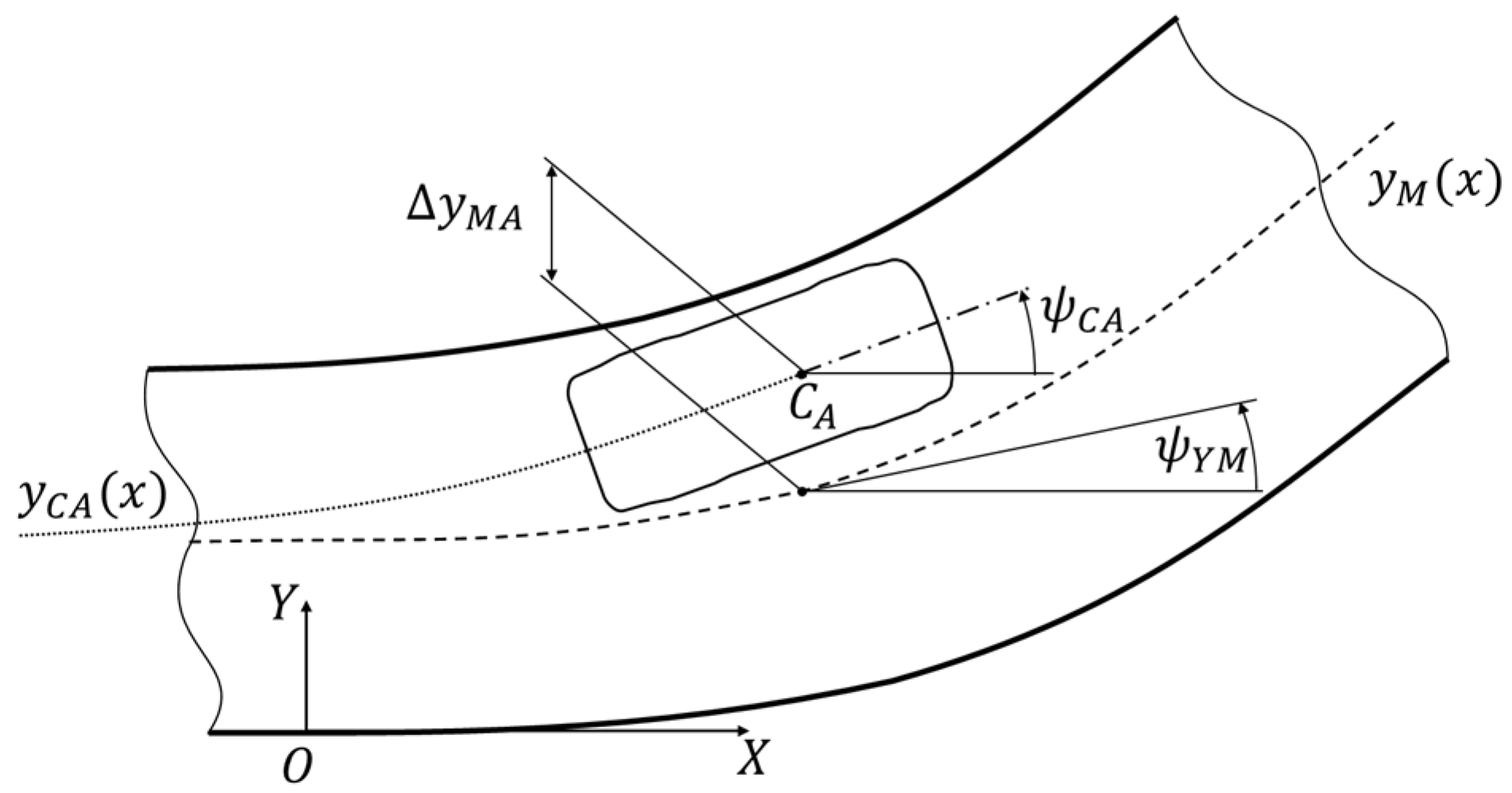
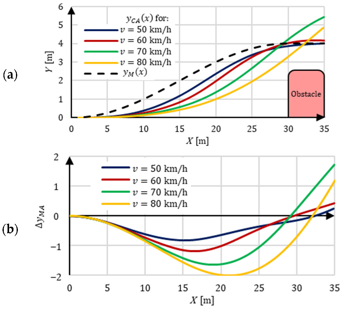
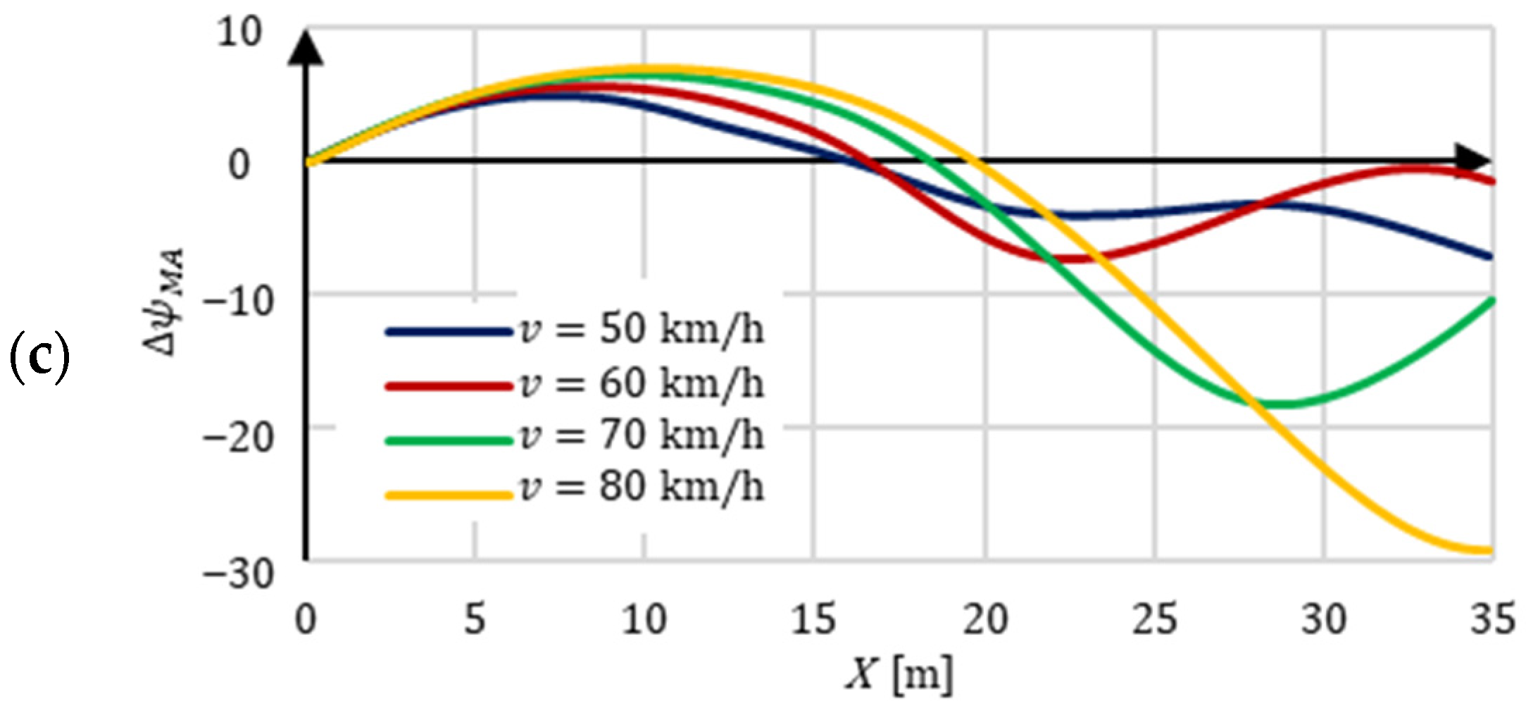
| Vehicle control system | The control process was carried out by turning the vehicle wheels. The value of the steering angle results from the need to keep the vehicle on the road lane. The necessary correction takes into account the lateral and angular deviation (Figure 4 and Figure 5) between the planned path and the actual vehicle trajectory. The deviations are measured from the center line of the road lane [31] or the reference trajectory [30]. For example, the control process in [30] was carried out in a feedback loop, in which the lateral deviation of the vehicle from the planned path was taken into account. This deviation was the basis for calculating the steering angle of the vehicle’s wheels. An actuator with a stepper motor was used to make the turn. |
| Additional information | In [32], HIL technology was used, in which computer simulation uses the position of the road lines and the vehicle. The position of the vehicle was simulated according to the so-called bicycle model (CarSim—Matlab software). Images from the computer screen, observed through the camera, were the basis (in the feedback loop) for the evaluation of the position of the vehicle in relation to the computer simulation. The difference of these positions makes it possible to calculate the necessary correction in the form of the steering wheel. However, the camera is sensitive to shocks and even its minimal displacement makes it difficult to detect lines on the computer screen and calculate the correct deviation from the planned path. |
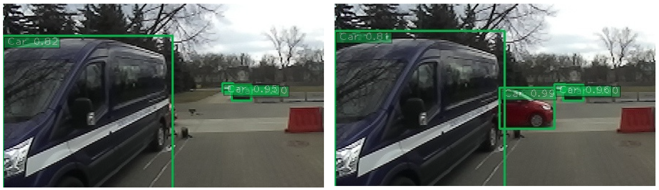
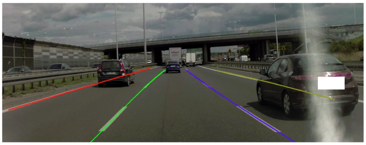
| Task and aim of the research | The research task in the described scenarios is automated lane detection and keeping [27], as well as avoiding a slower moving vehicle [33]. The aim of the research has two aspects: effective detection of road lane boundary lines in conditions of traffic with other vehicles and determination of a non-collision (safe) trajectory while avoiding a slower car. In [27], a scenario was used in which the perception system was tested in terms of its effectiveness in detecting lines on the road. A more complex research task covers the scenario in [33]. The task additionally includes determining a non-collision path of movement so as to obtain smooth avoidance of a slower moving car. |
| Research object | Passenger cars and their measuring equipment were used during the research. Little information has been provided about the equipment of the vehicle in [27]. The scope of the planned research indicates that the vehicle perception system (camera and software) was involved. |
| Research site/environment | In both scenarios, research was planned in an urban area. In [33], a section of the road was simulated in a closed area (e.g., with dummies). In this area, a two-lane roadway was separated, which made it possible to avoid vehicles. In this area, driving velocities reached up to 25 km/h. In [27], there was a limited stretch of road traffic used in the scenario. The car’s perception system was used during analysis of the effectiveness of detecting the road lane lines. |
| Vehicle control system | During the research in scenario [27], attention was focused on the effective detection of lane boundaries in urban conditions. Vehicles in scenario [33] performed automated driving by turning the wheels and selecting driving velocity. The choice of velocity took into account the limitations of driving safety and smoothness. |
| Additional information | The IMU sensors used are inertial sensors, hence, when measuring the angle of deviation of the longitudinal axis of the vehicle, it is necessary to include the deviation value, which makes the result susceptible to the phenomenon of drift [33]. In scenario [27], a neural network was used to estimate the safe driving distance. |
| Task and aim of the research | The research task related to avoiding a suddenly appearing obstacle. This research is a reference for active safety technology aiming to prevent road accidents. A scenario was used that involved two aspects of research: obstacle avoidance and braking. |
| Research object | The research subject was a single-person AV that performed autonomous driving during obstacle avoidance. The functioning of perception, risk analysis, and obstacle avoidance path planning systems was investigated. |
| Research site/environment | The research was conducted in a closed area. Cardboard boxes were used to define the research area (roads and obstacles). A velocity limit of 30 km/h was introduced. |
| Vehicle control system | The vehicle was controlled by the braking and steering systems. The location of the edge of the road and the obstacle allowed for geometric location (in global coordinates) of the obstacle avoidance trajectory. This made it possible to calculate the necessary correction of the trajectory compared to the planned path in the vehicle control system. |
| Additional information | Cardboard boxes are often used to mark road boundaries and obstacles. |
| Scope and Aim of the Research | Scenario Identification |
|---|---|
| Tests of the emergency braking system/collision warning system against an obstacle (vehicle, pedestrian, bicyclist). The aim of the test was to assess the effectiveness of a given AV system. Images from cameras and system interface signals were recorded. Measured values for the car: position, driving velocity, angular velocities, acceleration, steering wheel angular velocity, and the intensity of acceleration and braking. | Euro NCAP: AEB C2C (CCRs, CCRm, CCRb, CCFtap) [17], AEB VRU (CPFA, CPNA, CPNC [50,51], CPLA, CPTA, CPRA, CBNA, CBNAO, CBFA, CBLA) [43] |
| ISO: 15623 [41], 19237 [52], 22078 [53], 22839 [54] | |
| IIHS: AEB [48], P-AEB [49] | |
| UNECE: 152 ] [38] | |
| RuNCAP: AEB [55,56,57,58] | |
| Tests related to lane keeping, driver lane departure warnings, semi-automatic lane changes, and emergency lane keeping systems. The aim of the test was to assess the system’s effectiveness in different driving conditions (types of road lines and specificity of obstacles on the road). Images from cameras and system interface signals were recorded. Measured values for the car: position, driving velocity, angular velocities, and steering wheel angular velocity. | Euro NCAP: LSS (ELK, LKA, LDW) [28] |
| SAE: J2808 [47], J3045 [16] | |
| ISO: 11270 [59], 17361 [40], 21202 [42] | |
| UNECE: 130 [37], 157 [39] | |
| Tests of the system responsible for informing about speed limits and a system that adjusts driving velocity to road limits. The aim of the test was to assess the system’s effectiveness with different road types and driving velocities. Road infrastructure (road speed limit signs) and signaling of restrictions via the AV interface were recorded. | Euro NCAP: SAS (SLIF) [22] |
| EU 2021/1958 [18] | |
| Tests of the vehicle’s blind spot monitoring system and lane change support system. The aim of the test was to assess the system’s effectiveness in various road maneuvers. Images from cameras and system interface signals about lane departure hazards were recorded. Measured values for the car: driving velocity, acceleration, and steering wheel angle. | NHTSA: 812045 [44], 812317 [45] |
| ISO: 17387 [60] | |
| Tests of the driver warning system for excessive driving velocity on the curve of the road. The aim of the test was to assess the correctness of signaling related to excessive velocity on the curve of the road through the system interface. Arc radius value and overspeed signaling via the system interface were recorded. Measured values for the car: position and driving velocity. | ISO: 11067 [61] |
| Testing of the active cruise control system and the system that controls following the vehicle in front at low speeds (traffic jam assistant). The aim of the test was to assess the effectiveness of the system for different driving modes. Detected vehicles before the AV were recorded. Measured values for the car: AV motion parameters and distance to the obstacle. | ISO: 15622 [62], 22178 [63] |
| Testing of the assisted parking system, maneuvering aids system, and the system for predefined routes for low-speed operations. The aim of the test was to assess the effectiveness of parking area detection, detection of obstacles, scanning the space around the vehicles, path planning, and control. Images from cameras, information about obstacles, and signals from the scanning sensors were recorded. Measured values for the car: position and distance to the obstacle. | ISO: 16787 [64], 17386 [65], 22737 [66] |
| Aim of the Research | Artificial Objects | Role in the Research | Publication |
|---|---|---|---|
| Avoiding obstacles, braking in front of obstacles | Cardboard boxes | Marking a road lane | [34] |
| Control of the vehicle braking process | Dummy parts of the rear of a car body (stationary or movable) | Imitation of a car on the road | [72,93,94] |
| 2D and 3D obstacle identification | Road cones | Objects to be identified by the perception system | [67] |
| Critical maneuvers to avoid collisions with suddenly appearing obstacles | Soft wall covered with a metallized mirrored film | Obstacle on the AV’s driving path (stationary, mobile) | [55] |
| Critical maneuvers to avoid front-end collisions with suddenly appearing obstacles | Pedestrian, child, and bicyclist dummies on a moving platform; soft car target | Moving objects on the path intersecting with the AV’s driving path | [51,56] |
| Defensive maneuvers before the collision; the lane change problem | Susceptible obstacle on a moving platform | Moving objects on the path intersecting with the AV’s driving path | [17,28] |
| Parameter | Camera | Thermal Camera | Radar | Lidar |
|---|---|---|---|---|
| Resolution | Good | Good | Fair | Fair |
| Illumination | Poor | Good | Good | Good |
| Weather | Fair | Good | Fair | Good |
| Cost | Good | Fair | Poor | Poor |
| Research Scope of the Scenario | Type, Manufacturer, Model, and Selected Sensor Parameters | Publication |
|---|---|---|
| Lane keeping by AVs | Camera, Bosch (first generation, CMOS). | [32] |
| 3D obstacle detection, braking and avoiding the obstacle | RGB camera (H: 48 deg). | [72] |
| 2D obstacle detection, localization and object tracking, lane/road detection | Camera, Hitachi KP-F3 (R: 644 × 493 px.). | [70] |
| 3D obstacle detection | RGB camera (H: 90 deg, V: 30 deg, R: 1920 × 640 px.). | [25] |
| 2D and 3D obstacle detection, localization, tracking | Stereo camera. | [21,23,67,77] |
| 2D and 3D obstacle detection, localization, tracking, research of emergency braking/collision warning systems (car, pedestrian, bicyclist) | RGB camera. | [20,26,50,68,69] |
| 2D object detection, localization, tracking | Thermal camera. | [20] |
| Research of emergency braking/collision warning systems (car, pedestrian, bicyclist) | Camera in the Subaru EyeSight system. | [55] |
| Research of emergency braking/collision warning systems (car, pedestrian, bicyclist) | Camera in the Infinity FEB system. | [56] |
| Research of emergency braking/collision warning systems (car, pedestrian, bicyclist), research of the lane keeping/lane departure warning/semi-automatic lane change/emergency lane keeping systems, research of blind spot monitoring/lane change assist systems | RGB camera. | [17,28,43,44,51] |
| Lane keeping by the AV, 3D object detection | Stereo camera, Stereolabs ZED (R: 672 × 376 px., F: 100 Hz, Range: 25 m). | [31,79,96] |
| Lane/road detection, 3D object detection | Camera, Sony PC-350. | [27] |
| 3D object detection | Camera, Sekonix SF3321 (f: 30 Hz). | [24] |
| 2D and 3D object detection, localization, tracking | Camera, Logitech HD Pro C920 (R: 1920 × 1080 px., f: 30 Hz); Camera, Giroptic HD (H: 360 deg, R: 2048 × 1024 px., f: 30 Hz); Thermal camera, FLIR A320 (R: 380 × 240 px., f: 9 Hz); Thermal camera, FLIR A65 (R: 640 × 512 px., f: 30 Hz); Thermal camera, Tonbo Imaging Inc. HawkVision (R: 640 × 480 px., f: 25 Hz); Camera, New Imaging Technology NSC1003 (CMOS, R: 1280 × 1024 px., f: 25 Hz); Camera, Point Grey Two Flea/FL3-GE-28S4C-C (R: 1928 × 1448 px., f: 15 Hz); Camera, Carnegie Robotics Multi Sense S21 (f: 30 Hz). | [95] |
| 2D and 3D object detection, localization, tracking | Camera (H: 85 deg, R: 3840 × 2160 px., f: 30 Hz). | [75] |
| 2D and 3D object detection, localization, tracking | Stereo camera, Point Grey Bumblebee XB3 (BBX3-13S2C-38) (R: 1280 × 960 px., f: 16 Hz, H: 66 deg); Camera, Point Grey Grasshopper2 (GS2-FW-14S5C-C) (R: 1024 × 1024 px., f: 11 Hz, H: 180 deg). | [74] |
| 2D and 3D object detection | Logitech StreamCam (R: 1280 × 720 px., f: 60 Hz, H: 78 deg) | [97] |
| 3D obstacle detection | Leopard Imaging AR023ZWDR | [89] |
| Research Scope of the Scenario | Type, Manufacturer, Model, and Selected Sensor Parameters | Publication |
|---|---|---|
| Braking and avoiding the obstacle | Short-range radar (H: 30 deg, Range: 30 m, f: 76.5 GHz); Long-range radar (H: 20 deg, Range: 150 m, f: 76.5 GHz). | [71] |
| Braking and avoiding the obstacle, 3D object detection | Radar, Fujitsu Ten (Range: 120 m, H: 16 deg); Radar, Mitsubishi (Range: 150 m, H: 12–16 deg); Radar, Denso (Range: 150 m, H: 20 deg); Radar, Nec (Range: 120 m, H: 16 deg); Radar, Hitachi (Range: 120 m, H: 16 deg); Radar, A.D.C. (Range: 150 m, H: 10 deg); Radar, Bosch (Range: 150 m, H: 8 deg); Radar, Autocruise (Range: 150 m, H: 12 deg); Radar, Delphi (Range: 150 m, H:16 deg); Radar, Eaton (Range: 150 m, H:12 deg); Radar, Visteon (Range: 150 m, H: 12 deg). | [72] |
| Research into emergency braking/collision warning systems (car, pedestrian, bicyclist) | Radar, Continental ARS510 (H: 9 deg, Range: 120 m); Radar, Continental SRR510 (H: 90 deg, Range: 30 m). | [17,43,50,51,55,57] |
| Research into emergency braking/collision warning systems (car, pedestrian, bicyclist) | Radar in the Infinity FEB system. | [56] |
| 3D object detection | Radar, Delphi ESR 64. | [95] |
| Research Scope of the Scenario | Type, Manufacturer, Model, and Selected Sensor Parameters | Publication |
|---|---|---|
| Planning the driving path of an AV, 3D object detection | Lidar, Velodyne HDL-64E (H: 360 deg, Layers: 64, Range: 120 m). | [23,24,25,33,79] |
| Planning the driving path of an AV, braking and avoiding the obstacle | Lidar, Sick. | [34] |
| Braking and avoiding the obstacle, 3D object detection | Lidar, Mitsubishi (H: 12 deg, V: 4 deg, Range: 130 m); Lidar, Denso (H: 16 deg, V: 4.4 deg, Range: 120 m); Lidar, Denso (gen.II, H: 40 deg, V: 4.4 deg, Range: 120 m); Lidar, Nec (H: 20 deg, V: 3 deg, Range: 100 m); Lidar, Omron (H: 10.5 deg, V: 3.3 deg, Range: 150 m); Lidar, Omron (gen.II, H: 20–30 deg, V: 6.5 deg, Range: 150 m); Lidar, Kansei (H: 12 deg, V: 3.5 deg, Range: 120 m); Lidar, A.D.C. (H: 17 deg, Range: 150 m). | [CYT42] [72] |
| 3D object detection | Lidar, Velodyne HDL32E (H: 360 deg, Layers: 32, Range: 100 m, f: 10 Hz). | [67,78,95] |
| 3D object detection | Lidar, (H: 90 deg, Layers: 64). | [68] |
| 3D object detection | Lidar, Ibeo Lux 8 (H: 110 deg, Layers: 8, Range: 50 m). | [76] |
| Research into blind spot monitoring/lane change assist systems for Avs | Lidar. | [44] |
| 3D object detection | Lidar, Velodyne VLP-16 (H: 360 deg, Layers: 16, Range: 100 m). | [79,97] |
| 3D object detection | Lidar, Hesai Pandar 40p (H: 360 deg, V: 40 deg, Layers: 40, Range: 200 m, f: 10 Hz). | [75] |
| 3D object detection | Lidar SICK LMS-151 2D (H: 270 deg, f: 50 Hz, Range: 50 m). Lidar SICK LD-MRS 3D (H: 85 deg, V: 3.2 deg, Layers: 4, f: 12.5 Hz, Range: 50 m). | [74] |
| Planning the driving path of an AV, 3D object detection | Lidar Sick LD MRS (H: 94 deg, Layers: 8, Range: 200 m). | [19] |
| 3D obstacle detection | Lidar Velodyne VLS-128 (H: 360 deg, Layers: 128, Range: 245 m). | [89] |
| Research Scope of the Scenario | Type, Manufacturer, Model, and Selected Sensor Parameters | Publication |
|---|---|---|
| Planning the driving path of an AV, 3D object detection | GPS. | [19,33] |
| Planning the driving path of an AV, braking and avoiding the obstacle | IMU. | [33,34] |
| Lane keeping by the AV, 2D and 3D object detection, localization, tracking | GNSS RTK SwiftNavigation. | [31,75] |
| 2D and 3D object detection, localization, tracking | IMU Vectornav VN-100. Single RTK GPS Trimble AG GPS361. Differential RTK GPS Trimble Dual Antennas A BD982. | [95] |
| 2D and 3D object detection, localization, tracking | OXTS RT-Range. | [75] |
| 2D and 3D object detection, localization, tracking | GPS/INS NovAtel SPAN-CPT Align inertial and GPS navigation system. GPS/GLONASS dual antenna. | [74] |
| 3D object detection | IMU Xsens Mti-G. | [19] |
| 2D and 3D object detection | RTK GNSS GPS MRP-2000. | [97] |
| 3D obstacle detection | GPS/IMU with RTK Novatel PwrPak7 dual antenna. | [89] |
Publisher’s Note: MDPI stays neutral with regard to jurisdictional claims in published maps and institutional affiliations. |
© 2022 by the authors. Licensee MDPI, Basel, Switzerland. This article is an open access article distributed under the terms and conditions of the Creative Commons Attribution (CC BY) license (https://creativecommons.org/licenses/by/4.0/).
Share and Cite
Prochowski, L.; Szwajkowski, P.; Ziubiński, M. Research Scenarios of Autonomous Vehicles, the Sensors and Measurement Systems Used in Experiments. Sensors 2022, 22, 6586. https://doi.org/10.3390/s22176586
Prochowski L, Szwajkowski P, Ziubiński M. Research Scenarios of Autonomous Vehicles, the Sensors and Measurement Systems Used in Experiments. Sensors. 2022; 22(17):6586. https://doi.org/10.3390/s22176586
Chicago/Turabian StyleProchowski, Leon, Patryk Szwajkowski, and Mateusz Ziubiński. 2022. "Research Scenarios of Autonomous Vehicles, the Sensors and Measurement Systems Used in Experiments" Sensors 22, no. 17: 6586. https://doi.org/10.3390/s22176586
APA StyleProchowski, L., Szwajkowski, P., & Ziubiński, M. (2022). Research Scenarios of Autonomous Vehicles, the Sensors and Measurement Systems Used in Experiments. Sensors, 22(17), 6586. https://doi.org/10.3390/s22176586