1. Introduction
Radio-frequency (RF)-based device-free localization (DFL) systems monitor the target area by measuring changes in the radio channel. Persons or other objects can be detected [
1], counted [
2], and localized. An advantage of RF-based DFL systems is that channel measurements such as the received signal strength indicator [
3], channel state information [
4], or channel impulse responses (CIRs) are available for regular RF transmissions. RF-based DFL systems exploit the radio channel measurements as sensor readings.
We distinguish between wideband and narrowband radio technologies, where wideband or even ultra-wideband (UWB) technologies are evolving. In narrowband DFL systems, multipath propagation results in constructive and destructive interference and prevails in that changes in the channel state can be mapped reliably to specific regions [
5]. To overcome this drawback, the authors propose to combine multiple narrowband channels [
6,
7,
8], which is a development comparable to a wideband system.
The focus of the paper is on multipath methods for UWB DFL systems. The UWB radio chip Decawave DW1000 provides complex-valued CIR measurements that include information about the direct path (sometimes called line-of-sight path) and echo paths. These CIR measurements vary in the magnitude and phase of multipath components (MPCs) when persons move in the direct or any echo path. UWB enables the extraction of MPCs and, respectively, mapping those MPCs to the target area. The high bandwidth, in this paper, approximately 500 MHz, allows distinguishing of MPCs when they are 1 ns apart from each other in the time domain. This enables distinguishing whether a person is in the proximity of any signal path.
Multipath localization has been the focus of research for many years, e.g., many tag-based localization systems, i.e., systems that locate tags by calculating, e.g., the time-of-flight between the tag and anchors, already exploit multipath to reduce the number of required sensors [
9,
10,
11]. Different from DFL systems, tag-based localization systems see persons as obstacles that obstruct the line-of-sight path and, therefore, decrease the localization accuracy [
12].
In this paper, we investigate two DFL methods that we will enhance to cope with and benefit from multipath propagation: The first method is radio tomographic imaging (RTI). RTI maps the attenuation of radio links into a heat map and, thus, localizes a person, where a radio link is the radio communication between transmitter and receiver. As a main contribution, we enhance RTI to benefit from multipath propagation and, thereby, increase the likelihood of detecting a person in either the direct path or in echo paths resulting from reflections on walls. The second method, multi-static radar (MSR), exploits the fact that persons create reflections that change the CIR. MSR approaches map additional reflections within the target area, thus localizing the person.
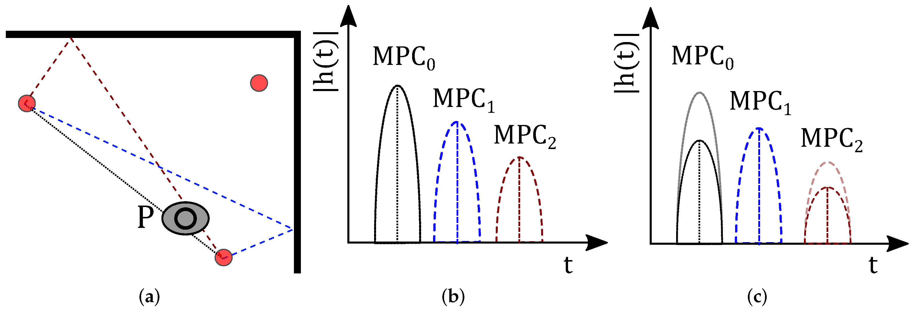
Figure 1 and
Figure 2 show the principle of how a person affects the channel measurement of both methods. Both methods will be described in detail in
Section 3. The red dots are sensor nodes that communicate via UWB radio technology. The black dotted line represents the direct path between each sensor pair. What is new in this work is that we consider also the echo paths (dashed lines), which are the first-order multipath components, i.e., RF paths based on a single bounce reflection on the walls depicted as the bold black lines in
Figure 1.
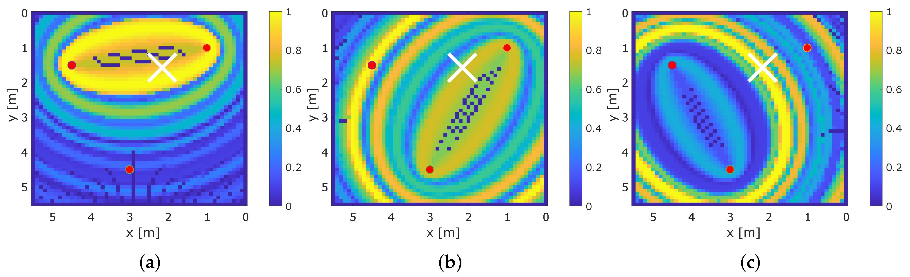
In the following, we describe how a person affects the MPCs that are extracted from the UWB CIR measurement: In
Figure 1a, the person
P located at position
affects the direct path between two sensors (
) and the red dashed echo path (
). When the target area is vacant, i.e., free of additional persons, we measure an idle CIR and determine the magnitude of the MPCs (see
Figure 1b). We will later use this idle case to subtract the background and identify changes in the MPCs due to the position of the person. Changes in the respective MPCs, in comparison to the idle CIR, shown in
Figure 1c, limit the possible locations of the person. To find the position of the person, radio tomographic imaging (RTI) [
6,
7,
13,
14] or fingerprinting (FP) algorithms [
15,
16,
17] are used. RTI algorithms map changes in the signal paths and display them in a heat map. In this work, we enhance RTI both to use the direct and echo paths of the UWB signal and describe the mapping of changes in the MPCs into a heat map. Fingerprinting algorithms compare the distance of the channel measurements prerecorded at reference positions with measured observations to determine the position of the person. Other possibilities for localization are geometric approaches [
18] and compressed sensing [
19,
20].
MSR approaches utilize changes within the UWB CIR (see
Figure 2). In
Figure 2a, the person stands in the middle of the target area. Here, he/she does not block any signal path of the sensor pair. In the CIR, we will see a new MPC by the reflection at the person. Different from RTI, MSR does not depend on the blocking of the signal paths. After background subtraction, it detects and exploits significant changes in the channel measurement.
Figure 2b shows the CIR measurement while the target area is vacant (black dotted CIR). A person that stands in the middle of the target area (see
Figure 2a) creates an additional MPC named
, shown in
Figure 2b as the red dotted line. Subtracting the CIR of the non-idle case from the CIR of the idle case shows differences due to the person within the target area; this step is called background subtraction. MSR now maps the time delay of the newly occurring MPC, which limits the possible position of the person within the target area.
In this work, we address multipath propagation for RTI and MSR. Furthermore, we propose to apply both DFL methods to the same set of UWB CIR measurements. We compare RTI, MA-RTI, and MSR within a real measurement setup and propose a novel scheme that combines MA-RTI and MSR to combine their advantages. We perform UWB CIR measurements with a commercial off-the-shelf (COTS) radio chip, the Decawave DW1000. Different from the Bayes methods such as Kalman or particle filters [
21,
22], MA-RTI and MSR create intuitive heat maps of the target area. A deeper understanding of the advantages of the effect on the CIR will also lead to better filters in the future. To the best of our knowledge, the combination and comparison of those DFL methods from real CIR measurements have not been performed before.
Our contributions are as follows:
We demonstrate how to exploit information from UWB CIR measurements to derive the position of a person within a target area with different DFL methods, namely RTI, MA-RTI, MSR, and a combination of MA-RTI and MSR.
We enhance RTI methods to benefit from multipath to reduce the number of required sensors and make RTI more robust against multipath propagation.
We test MSR under real conditions and propose to defeat multipath propagation by the so-called background subtraction.
We compare RTI, MA-RTI, and MSR and combine MA-RTI and MSR within a test setup.
The rest of the paper is structured as follows:
Section 2 presents the related work of DFL systems and multipath models. In
Section 3, we propose the idea of the solution, including a novel multipath-assisted RTI method, an MSR method, and their combination.
Section 4 shows the details of the implementation, such as the measurement hardware, firmware, measurement setup, and processing of the measurements. We evaluate the DFL methods and their combination in
Section 5. Finally, we conclude our work and give an outlook for future work in
Section 6.
2. Related Work
In this section, we provide a brief overview of the related field in the research on DFL systems. Youssef et al. proposed the first DFL system based on fingerprinting in [
15], enabling research in this field. A few years later, Wilson and Patwari proposed RTI, an approach that avoids the extensive training phase of a fingerprinting system, but requires many sensors [
13].
One major challenge of DFL systems, especially in indoor environments, is multipath propagation, which leads to the constructive and destructive interference of the received signal [
5]. When multipath propagation affects the channel measurement more strongly than the person, the performance of the DFL system degrades.
Although modeling the influence of a person and multipath propagation on the received signal is possible [
5], such approaches require exact knowledge of the sensor and multipath positions, which is impractical in real deployments. Therefore, different authors proposed to combine several RF channels for DFL and chose the radio links that are least affected by multipath or combined the results [
6,
7]. Schröder and Wolf provide another possibility to avoid narrowband channel measurements in [
23]. They swept through the 2.4 GHz ISM band and recorded the measured phase between two IEEE 802.15.4 nodes.
UWB radar sensor networks aim to localize persons within a target area, e.g., mono-static UWB sensor radar networks are proposed in [
24,
25]. Mono-static UWB radar sensor networks require that the same sensor node be able to receive the transmitted UWB pulses, e.g., with a second receive antenna. Multi-static UWB radar sensor networks are proposed in [
26,
27,
28]; there, one sensor node transmits UWB pulses, and at least one different node acts as the receiver. Those approaches have in common that they calculate the time-of-arrival upon receipt of the signal. With this information, tracking is performed, e.g., with the help of particle filters.
Different from our MSR approach, the authors acquired the time-of-arrival information upon receipt of the UWB pulses. Our solution is based on a COTS UWB radio chip, the Decawave DW1000, which enables the extraction of CIR measurements. The extracted CIR is processed, and information about the person is extracted and compared with several DFL methods.
UWB CIRs enable the exploitation of multipath components and can be measured using COTS low-cost UWB radio chips. On the one hand, UWB signals reduce the effect of multipath propagation for DFL systems. On the other hand, this helps reduce the number of required sensors for localization. In [
29], Moschevikin et al. described a method to carefully align CIR measurements of the Decawave DW1000, enabling pre-processing of the CIR. To model changes in the magnitude and phase of the UWB CIR due to the position of a person, we refer to [
30]. In previous work, we proposed to exploit multipath propagation, as well as the magnitude and phase of UWB CIRs to increase the accuracy of DFL systems and to reduce the number of physical sensor nodes [
31,
32]. However, those approaches depend on fingerprinting algorithms, which require an extensive training phase. Therefore, in this paper, we focus on methods that only require idle measurements for calibration and background subtraction.
RTI has been excessively researched for narrowband DFL systems [
6,
7,
8,
13]. To the best of our knowledge, there have been only a few works including multipath propagation in RTI systems. In narrowband DFL systems, multipath propagation typically reduces the accuracy of RTI [
33]. Kim et al. created a system that includes multipath with mmWave radios [
34]. In [
35], Zhang et al. introduced RTI with multipath, and for that, they included angle-of-arrival measurements with RFID. In this paper, we propose multipath-assisted (MA)-RTI, which extracts MPCs from the UWB CIRs and, therefore, benefits from the echo paths of the signal.
Next to conventional DFL approaches such as fingerprinting or RTI, UWB CIR measurements enable MSR approaches. Ledergerber et al. proposed an MSR based on UWB [
21]. From the variances of the UWB CIR measurements, they extracted the time delay of the new reflection and determined the position of a person with a particle filter. In [
36], Li et al. used the dataset provided by Ledergerber et al. [
21] to track persons. They used a convolutional neural network for time-of-flight estimation and deployed a particle filter for tracking persons. In [
37], the same authors elaborated on practical concerns of MSRs for pedestrian tracking. Bocus and Piechocki used the dataset from Ledergerber et al. to implement passive tracking [
38].
Another possibility to set up MSR is to draw the CIR differences in ellipses on the target area, as performed in [
39] in an anechoic chamber. Later, Ninnemann et al. applied this technique for the occupancy detection of cars [
40] and for detection of persons within an aircraft cabin [
41]. As MSR is a promising approach, we adapted the MSR approach proposed in [
39] and tested this approach under multipath conditions and with a person to be localized. Therefore, we added a background subtraction, as proposed in [
40].
In [
42], Hong et al. proposed a device-free angle-of-arrival estimation with UWB signals. Exploiting the angle-of-arrival measurements increases the accuracy; however, this requires multiple antennas on the receiver side. Furthermore, UWB CIR responses enable device-free activity detection, as shown in [
43]. Other approaches include MPCs with Bayesian filtering to localize and track a person [
22].
Recent research proved that MSR algorithms detect and track persons by variations of the UWB CIR. However, those methods rely on the dynamic variation of the CIR (e.g., the variances). Such approaches perform well in scenarios with moving persons, but fail with static persons. In this paper, we strive for two goals: First, we propose to enhance RTI by processing multipath signals that are extracted from a UWB CIR. Second, we combine MA-RTI with MSR. Both methods were extracted from the same UWB CIR. To the best of our knowledge, a comparison and combination of those DFL methods based on UWB CIRs has not been proposed before.
3. Approach
In the first part of this section, we describe the signal propagation including multipath components (MPCs). In the second part, we propose multipath-assisted (MA) radio tomographic imaging (RTI), a DFL method that uses MPCs for the localization of the person. We describe how RTI is applied to the direct and echo paths that are extracted from UWB CIR measurements to decrease the number of physical sensors needed. In the third part of this section, we present multi-static radar (MSR), an approach that scans the CIR for new reflections in order to detect the person.
3.1. Signal Propagation Including Multipath Components
In this paper, we extract and exploit MPCs from the UWB CIR. Therefore, we describe the propagation of UWB signals in this section.
A UWB pulse
sent by the transmitter
is sensed by the receiver
. The pulse propagates in a direct path between
and
and additional echo paths reflected on walls and other obstacles. All signal components are received by
. The echos of
passing the
i-th path are received with a corresponding time delay
and a decreased amplitude
. The CIR
depicts the multipath propagation of all
I signal echos between
and
:
where
is the Dirac function.
The received signal
at
is a superposition of all received signal echoes:
where
is additive white Gaussian noise [
44].
Figure 3 shows an exemplary multipath scenario with two walls. The black dotted line between Sensor 1 and Sensor 2 is the
-th component, which is the direct path between the transmitter and the receiver. Additionally, we depict echo paths that are the first-order MPCs in blue and brown dashed lines. To determine the echo paths, the positions of virtual sensors
, and
are calculated. These virtual sensor positions result from mirroring the physical sensor positions on the walls, as shown as the gray line in
Figure 3 on Sensor 1, e.g., the upper reflection (brown dashed line) is calculable with respect to virtual sensor position
. The path length of the connection between 2 and
equals the MPC’s length, and the connection’s intersection with the wall is the reflection point of the MPC. Therefore, we determine the path length and the resulting time delay
.
3.2. Multipath-Assisted Radio Tomographic Imaging
Radio tomographic imaging (RTI) creates a heat map from the target area. A person will mainly affect an MPC when he/she is present within the first Fresnel zone of the respective path. This usually results in blind spots or the deployment of many sensors. Therefore, RTI approaches require typically 10–20 sensors to achieve a sophisticated accuracy [
6,
7,
8,
13].
One contribution of this paper is exploiting multipath propagation for RTI and proving that this multipath-assisted (MA) approach works with only a few physical sensors.
3.2.1. Including MPCs in RTI
Narrowband RTI systems rely on channel measurements of radio links and are affected by multipath propagation. UWB CIR measurements enable the extraction of multiple MPCs from the CIR. In the following, we focus on an exemplary multipath scenario including two walls, as shown in
Figure 3. To exploit the MPCs for RTI, every sensor position is mirrored on each wall, resulting in additional virtual sensor positions
and
for the top wall and
and
for the right-hand wall. In the following, we use the permutations of the physical and virtual sensor pairs, namely
,
,
, and
. Together with the direct path
, this results in five different MPCs for each sensor pair, increasing the conventional number of paths by four echo paths, even for this simple setup. The difference from the conventional RTI system is that the former solely exploits the direct path
for the localization of a person. Note: With the permutations of the physical and virtual sensor pairs, we map each echo path onto the target area. As we extract the values for an echo path from the CIR, both the incident and the reflected ray will receive the same complex value. For RTI, the measurement vector
depicts the difference between the observation and the idle case modeled in a single value. For the
i-th MPC,
is defined as:
where
is the signal power of the observed and idle CIR at
, respectively. The more the person affects the MPC on the direct or echo path in comparison to an idle target area, the higher the input for MA-RTI is.
In this paper, we deploy the absolute difference for each MPC as the input for the MA-RTI system, as described by (
3).
Note, many narrowband RTI systems reduce the impact of multipath propagation, by calculating other features such as the variance as the input vector
[
7]. Using the variance, however, inherits the problem that the feature decreases when the person stands still within the target area. Although UWB signals are also affected by multipath propagation [
45], extracting MPCs from the UWB CIR reduces the problem.
3.2.2. Principle
In the following, we describe the principle of MA-RTI. First, we divide the target area A into J equally sized pixels. Each pixel has an assigned attenuation value, which is subject to be estimated from a measurement. The heat map (also called attenuation image) is represented by vector . A matrix of size assigns weights to the heat map. As a result, is the measurement vector of length I, with I being the number of the direct and echo paths (in our case, the MPC components of all sensors).
RTI systems are based on a simple linear model [
13]:
where
is
I-dimensional normally distributed noise.
The weight
for each path
i and each pixel
j is determined by the following equation [
13]:
where
is the distance from Sensor 1 to Sensor 2 on the
i-th path over the center of pixel
j,
is the distance of the
i-th path, and
is a tuning parameter in
[
13].
Figure 4 depicts the parameters. When the pixel
j is inside an ellipse with the sensors in its foci, then the weight
is assigned; otherwise, the weight is 0. When a person is outside the direct or echo path, this path will not affect the RTI system. The tuning parameter
controls the width of the ellipse.
In the following, we discuss solutions for linear equations such as (
4). Such equations are typically solved by L2-minimization (
6):
which leads to the well-known solution:
where
is the Moore–Penrose pseudo-inverse of
. Each weight
for each path
i and each pixel
j is calculated as described in (
5).
However, this approach leads to reliable results only if (
7) is well conditioned, i.e.,
has rank
J. Unfortunately, this is not the case for an RTI system as the number of paths
I is smaller than the number of pixels
J. RTI is an ill-posed inverse problem; many pixels are estimated by a low number of paths, so
. In addition, there are pixels that are not crossing any path; therefore, any measurement will lead to the same result, which causes an overall under-determined system [
13].
Solving the equation requires regularization of the pseudo-inverse with a covariance matrix of
v weighted by
. The elements of the covariance matrix are defined as [
13]:
where
is the distance from pixel
k to
l,
a space constant, and
is the pixel variance of the estimation error. Such an exponential covariance is a common approximation of a spatial attenuation, which is modeled as a Poisson process [
13].
Including the covariance matrix in the calculation of the pseudo-inverse, (
7) becomes:
We determine the estimated position of the person
by searching the maximum value in
:
where operator
returns the position vector of the
j-th pixel.
Finally, we normalize to result in .
3.3. Multi-Static Radar
This section describes MSR, a method that maps the CIR to a target area. The idea of this DFL method is to detect and track persons outside of MPCs. Instead of only finding the time delay of the reflection and inserting this into a particle filter [
21], we map the whole CIR difference to the target area as proposed in [
39]. One contribution of this paper is adapting the MSR approach of [
39] and evaluating this method in multipath conditions. Therefore, we performed measurements outside an anechoic chamber, and different from [
40], we localized a person instead of a parking car.
Idea: we will both use parts of the CIR (e.g., the magnitude of the I MPCs) and the complete time series. We expect that MSR works well for positions where a person does not affect a multipath component. Therefore, MSRs localize persons at positions where RTI systems provide low localization accuracy.
3.3.1. Principle
An MSR detects a person with changes in the received signal compared to the idle case. The transmitter and the receiver are placed at known positions. Emitted signals by are received at on the direct path and via echo paths on persons. In a target area without walls, we expect only the direct path. When there are echo paths available, a person must be present.
Figure 2c shows that the person causes a new
at the time
. With the speed of light
, the distance
between the transmitter with position
over the person at
to the receiver at
is defined by [
39]:
where
models the measurement error. The solution space for
draws an ellipse with
and
in the foci, as illustrated in
Figure 5.
If the system utilizes
o different sensor permutations, the solution
is found by solving a non-linear system of equations [
39].
Figure 5 also presents the parameters of the ellipses. The path length
between
and
is constant.
a being the semi-major axis of the ellipse,
b is the semi-minor axis
b and is calculated as
.
The UWB CIR represents the received signal over time. Every peak in the CIR is a potential person; the higher the peak, the more probable the location of the person is. To localize the person, we draw the peaks onto the target area. The position of , as well as must be known as they are the foci of the ellipse.
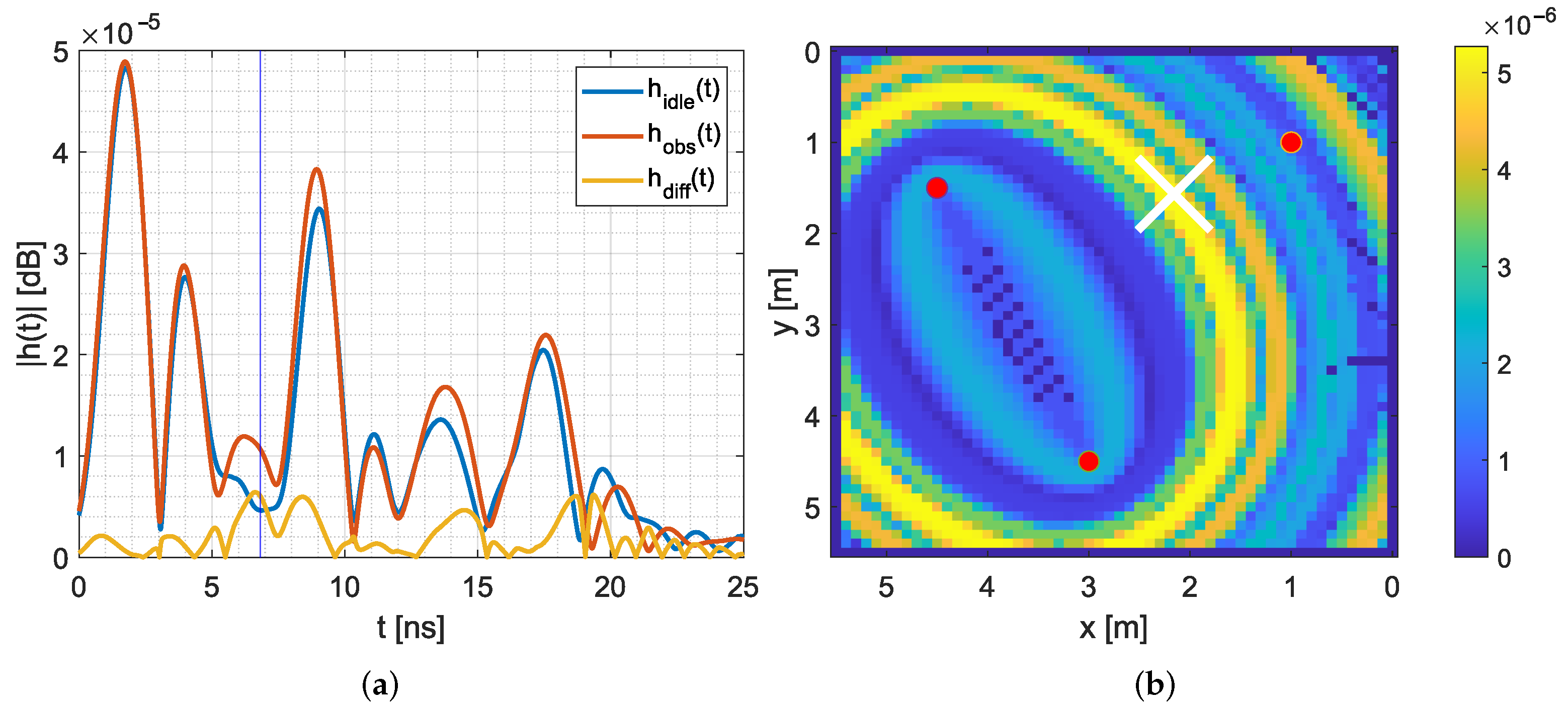
Figure 6 provides an example.
Figure 6a depicts the measured and pre-processed CIR for the idle case
(blue CIR) and when a person is located in the target area
(red CIR). The blue vertical line at 7 ns represents the expected time delay
due to the position of the person.
, the direct path, is located at 2 ns. As the direct path was not blocked by the person, this is the highest peak. The MPCs are at 9 ns and at 17 ns. Around 7 ns, we expect changes due to the position of the person, and indeed, the CIR differs from the idle case.
We calculate the difference
between the observed CIR
and the idle CIR
, shown as the yellow line in
Figure 6a. The highest differences
are at 7 ns and at 8.5 ns, so very close to the time delay of the person. The CIR difference is now mapped as a heat map onto the target area (see
Figure 6b). Starting at the peak of
, we draw an ellipse onto the target area with the height of the corresponding CIR difference. The white cross in
Figure 6b indicates the position of the person; it lies near the perimeter where the maximum of the CIR difference is located.
To map the values of the CIR to the target area, each ellipse must be rotated and calculated [
39]. For this, we calculate the center of the ellipse
with:
Next, we need the rotation of the ellipse:
Based on these values, we determine the radius of the ellipse within
:
3.3.2. General Approach
In the following, we describe how we map the ellipses for each sensor pair o onto the target area. For each sensor pair, one sensor will act as the transmitter and the other as the receiver.
Similar to MA-RTI, we divide the target area A into J equally sized pixels. Then, we create a heat map for every sensor pair o.
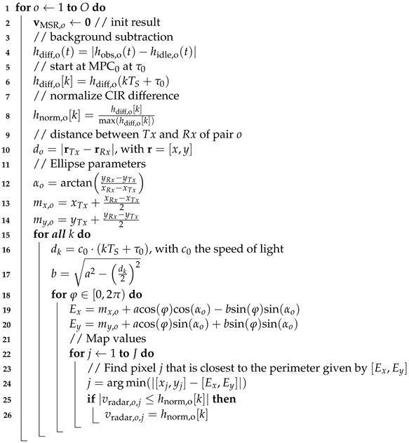
Algorithm 1 shows the pseudo-code that calculates the heat map
for every sensor pair
o. The idea of applying MSR is to extract additional changes within the CIR coming from persons. To detect changes in the CIR coming from the person, we perform so-called background subtraction as suggested by [
46]. Therefore, for every sensor pair
o, we calculate the difference:
where
is the current observation and
the idle CIR measurement while the target area was vacant.
The background subtraction focuses on the difference between the idle and the measured CIR measurement. By analyzing the difference, the influenced MPCs are detected. However, signal echoes on paths with a similar transmission delay
interfere and, finally, superpose in the CIR measurement
. Therefore, in the case of signal echo interference, the analysis will lead to ambiguous results, reducing the localization performance of the method.
| Algorithm 1: Pseudo-code for multi-static radar heat map calculation adapted from [39]. |
![Sensors 22 06255 i001]() |
In [
45], we discussed an algorithmic approach to detect and identify also interfering signal echoes successively up to a certain transmission delay difference
. However, since the placement of the anchor nodes was freely chosen in our setup, later on, we focus on anchor positions, where all transmission delays of the MPCs are distinct. Therefore, we can neglect the influence of interference in this case.
We start the mapping of the CIR difference at the peak of
:
After background subtraction, we normalize the CIR difference:
This implies that every sensor pair has the same weight.
As described in Algorithm 1, starting from the peak of
, we calculate the ellipses with steps of
according to (
16), meaning that we calculate one ellipse for every 1 ns in the CIR and map them to the target area. The mapping works as follows: For every
and
, we find the closest pixel and assign the value of the normalized CIR difference, when the current normalized CIR difference is larger than the previously saved one.
Figure 6b shows the result for an ellipse that is mapped to the target area.
Finally, we calculate the mean of the heat maps:
To localize the person, we determine the maximum:
3.4. Combination of Both DFL Methods
One contribution of this paper is the combination of MA-RTI and MSR. We expect that MA-RTI performs well on positions that are covered by multiple MPCs. In contrast, we expect that MSR performs well on positions that are uncovered by MPCs. In such cases, the background subtraction will be effective, and a person affects the measurements. As both methods can be applied to the same UWB CIR measurement, we expect that the combination of both methods increases the localization performance.
Both DFL methods create a heat map. MA-RTI results in
(see (
9)); MSR results in
(see (
20)).
As
and
are normalized, we calculate the combination of both approaches by pixelwise multiplication:
is the same size as its predecessors. As for MA-RTI and MSR, we determine the most likely position by searching the maximum
4. Implementation
In this section, we provide implementation details on the test setup including the hardware and software considerations. In the first part of this section, we showcase the hardware that runs the UWB radio chip, the Decawave DW1000. In the second part of this section, we introduce our firmware, which creates and extracts the CIR measurements on the sensor nodes. In the third part of this section, we present the pre-processing that is applied to the UWB CIR measurements and demonstrate how the MPCs are extracted from the UWB radio chip. In the fourth part, we provide an overview of the measurement setup that was used for the evaluation of the different DFL methods. Finally, we conclude this section by describing the flow chart of the algorithms. We provide the measurement data in the
Supplementary Materials.
4.1. Hardware and Radio-Frequency Settings
In this subsection, we depict the measurement hardware and the chosen RF settings of the Decawave DW1000 radio chip.
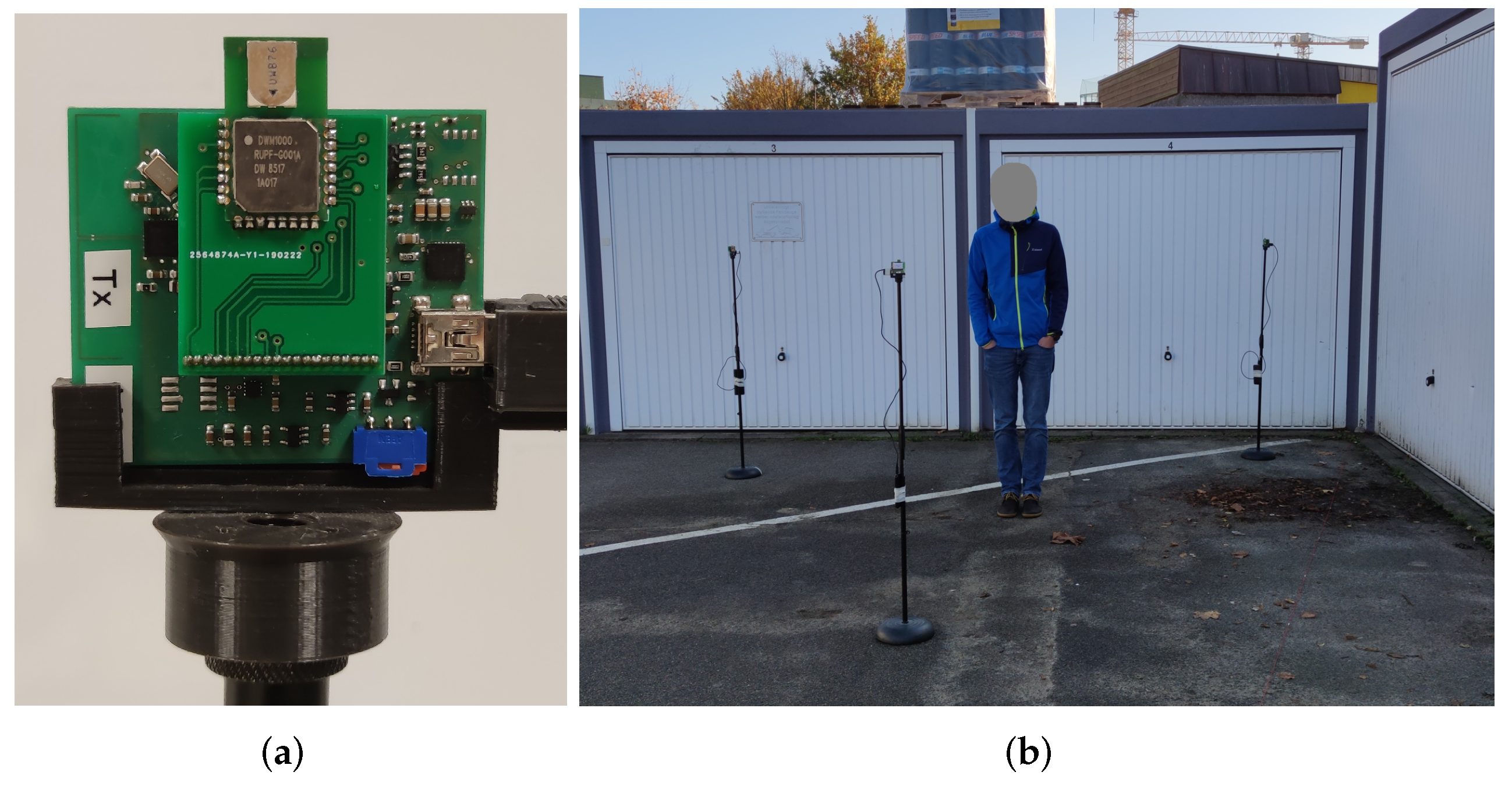
Figure 7a shows a sensor node, which is our TinyTriSOS platform utilizing a DW1000 UWB radio chip, which is controlled by an ATXMega128A1. During the measurements, the sensor nodes are powered via USB while mounted on a microphone stand at a 1.5 m height.
Table 1 provides the setting of the UWB radio chip.
4.2. Firmware
The firmware controls the sensor nodes to exchange data via the UWB radio. Upon reception of an UWB message, the CIR and other relevant parameters are saved and transported via UWB in the next cycle. The goal of the firmware is that one node that acts as the listener listens to the communication that saves and transports the CIR payload. Next to the CIR measurement, the CIR payload contains assisting parameters that are reported by the Decawave DW1000. The listener is connected via a serial interface to a computer that logs the incoming messages.
Table 2 provides the information of the payload each node transmits. The CIR is the most important variable; for each CIR sample, we save the real and imaginary parts as a uint16_t. Currently, we measure 60 CIR samples, resulting in
Byte as a payload. A signal with the speed of light
travels approximately 0.3 m/s. Therefore, 60 ns of the CIR covers MPCs up to a distance of approximately 18 m. As an IEEE 802.15.4 frame has a maximum of 127 Byte, we had to enable extended length data frames, which enabled us to transmit frames up to 1023 Byte [
47]. With the current version of the firmware, we were able to transfer CIRs measurements at approximately 20 Hz.
4.3. Pre-Processing of CIR Measurements
After measuring the CIR, we performed the pre-processing that we proposed in [
31]. The goal of the pre-processing is to align the CIRs in time and to increase the resolution by suitable sinc-interpolation. In the following, we briefly summarize the pre-processing of the CIRs.
The measured CIR is a series of K I/Q values with . The bandwidth of our chosen IEEE 802.15.4.a channel is MHz, resulting in ns. In the firmware, we decided to set samples, which allowed us to capture a CIR with a maximum length of approximately 60 ns.
We resampled the CIR with
and applied sinc-interpolation, resulting in
(
), to increase the resolution. After interpolation, we aligned the CIRs in time. For time alignment, we used the timestamp from the leading edge detection of the Decawave DW1000. This timestamp is based on an integer value that has an accuracy of about 1 ns and a fine-grained fractional part that provides the result of the leading edge detection below 1 ns. We recorded and transmitted the CIR measurements of five samples prior to the reported integer part. After time alignment, we scaled each CIR with its reported
, which is given by (
25). Finally, we cropped each CIR to be exactly
N samples long. The resulting CIR is
, with
. For the detailed information and example source code for the pre-processing, we refer to [
31]. There, the alignment of the CIR in time and sinc-interpolation is explained in more detail.
4.4. Extraction of MPCs from UWB CIR Measurements
This section describes how the MPC values are extracted from the pre-processed UWB CIR. After extraction, the values are used for MA-RTI and MSR.
Equation (
24) calculates the magnitude of the MPC in dBm:
where
,
, and
are the magnitude values of the CIR at time
.
is the preamble accumulation count, and the constant
dB is valid for the chosen pulse repetition frequency of 64 MHz [
47].
After calculating the magnitude of each MPC, we scaled
with the reported receive power level
of the measured CIR. Based on [
47],
in dBm is calculated as
For MA-RTI, we determine the input vector
as follows:
For this, we extracted for the idle reference CIR and the observation CIR the power of each MPC
with (
24).
4.5. Measurement Setup
In the following, we outline the details of our measurement setup.
We measured in an outdoor scenario, with two walls (garage doors) that create strong reflections.
Figure 7b shows an photograph of the setup,
Figure 8 depicts the sensors and measurement positions together with the signal paths. We decided on this setup because it creates sufficient MPCs to compare the different DFL methods, without too many parasitic effects, like in an indoor environment. Still, measuring an outdoor environment creates more MPCs than measurements within an anechoic chamber [
39].
The three sensor nodes were mounted on microphone stands at a 1.5 m height (depicted as red dots in
Figure 8). Sensor 1 was placed at the (
x,
y)-coordinate (1 m,1 m), Sensor 2 at (4.5 m,1.5 m), and Sensor 3 at (3, 4.5 m), respectively. The target area spans 5.5 m in the x- and y-direction. Based on the position of the sensors and the walls, we determined the time delays for the sensor pair (1,2) with
ns,
ns, after
. For sensor pair (1,3), we found
ns and
ns after
, and for sensor pair (2,3), the delays were
ns and
ns.
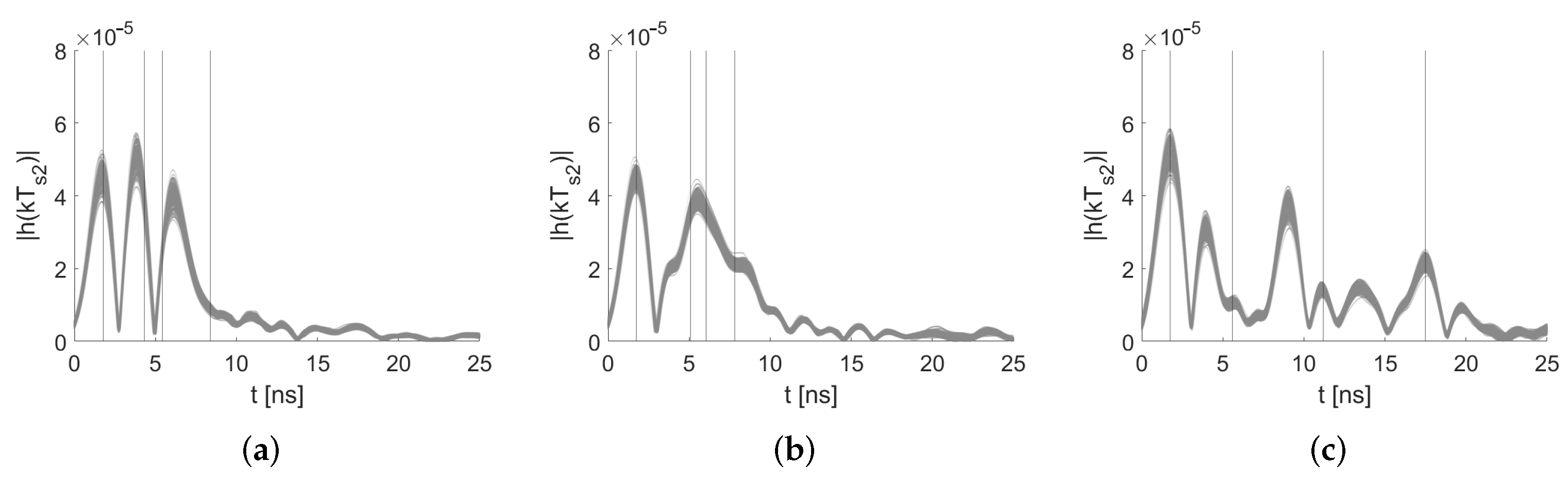
Figure 9 shows the pre-processed idle measurements of the three distinct node pairs. The determined first-order MPCs are depicted with solid lines. Due to superposition, the signal echoes interfere constructively and destructively and lead to the vanishing of the expected maxima. We took a closer look at this behavior in [
45]. The first line indicates the peak of
at
; the other peaks are the theoretical positions of the MPCs. Due to constructive and destructive interference and inaccuracies in the signal paths, the position of the MPCs does not always match the maximum in the CIRs. Still, those values are required for the extraction of the MPCs for MA-RTI. In the following, we briefly discuss the effect of the misalignment of the theoretical MPCs for MA-RTI and MSR: For MA-RTI, we extract the complex values of the CIR at the respective misaligned MPCs delay. This is sup-optimal, however; a person in the proximity of an MPC will also affect the CIR in direct proximity. For MSR, the misalignment between the theoretical positions of the MPCs and the measured ones is neglectable, as we used idle measurement (with the same misalignment) for background subtraction. Note: especially at peaks in close proximity, we expect that there is no misaligned, but superposition of MPCs. To detect this, we will apply an algorithmic approach in the future; however, this is out of the scope of this paper [
45].
Next to the idle measurements, we recorded at each of the 19 different reference positions CIR measurements while a person with a height of 1.95 m, a shoulder-to-shoulder length of approximately 0.45 m, and back-to-chest length of approximately 0.25 m was standing at each position. During the measurements, the person stood still, the body facing towards the south of the measurement setup. Outside of the setup, the listener node receives the UWB transmissions and forwards the data via a serial interface to a laptop, which saves the data.
Figure 8 summarizes the measurement setup with its three sensors (red dots) and 19 reference positions (black dots), as well as the signal paths up to the first order (dashed lines) between the sensor nodes. This set of reference positions enabled us to examine the advantages and disadvantages of the proposed DFL methods. Note: typically, RTI systems place sensors in a way that many signal paths cross the target area. Positions without crossing signal paths are then neglected. In contrast, MSR requires that the target area be far away from the signal paths, so that the person creates additional changes in the CIR that can be detected and processed. In the following, we describe the characteristics of the positions that are a mixture of both cases.
The measurement setup provides reference positions that cover both cases. The different positions are motivated as follows. Position 2 is approximately 0.5 m away from signal paths; therefore, we expect that this is ideal for localization with MSR. Many reference positions cross the direct path between the sensors, therefore, enabling us to determine the effect on blocked paths. The first three positions are outside the area that the direct paths of the sensors span, e.g., position 2 and position 3 are not crossed by signal paths. The fourth position is in direct proximity to the direct path and the echo path of the sensor pair (1,2) and additionally crosses the echo path of the sensor pair (2,3). Positions 6–8 are in the middle of the target area, resulting in that they are not in the proximity of the direct paths and cross only a few echo paths. We expect that MSR will perform well in those positions. Position 10–14 are placed close to the direct path of the sensor pair (1,3), and we expect MA-RTI to localize the person in those positions. Positions 15–19 are outside the middle of the target area, and only positions 16 and 18 cross an echo path. We provide the measurement data in the
Supplementary Material.
4.6. Algorithms
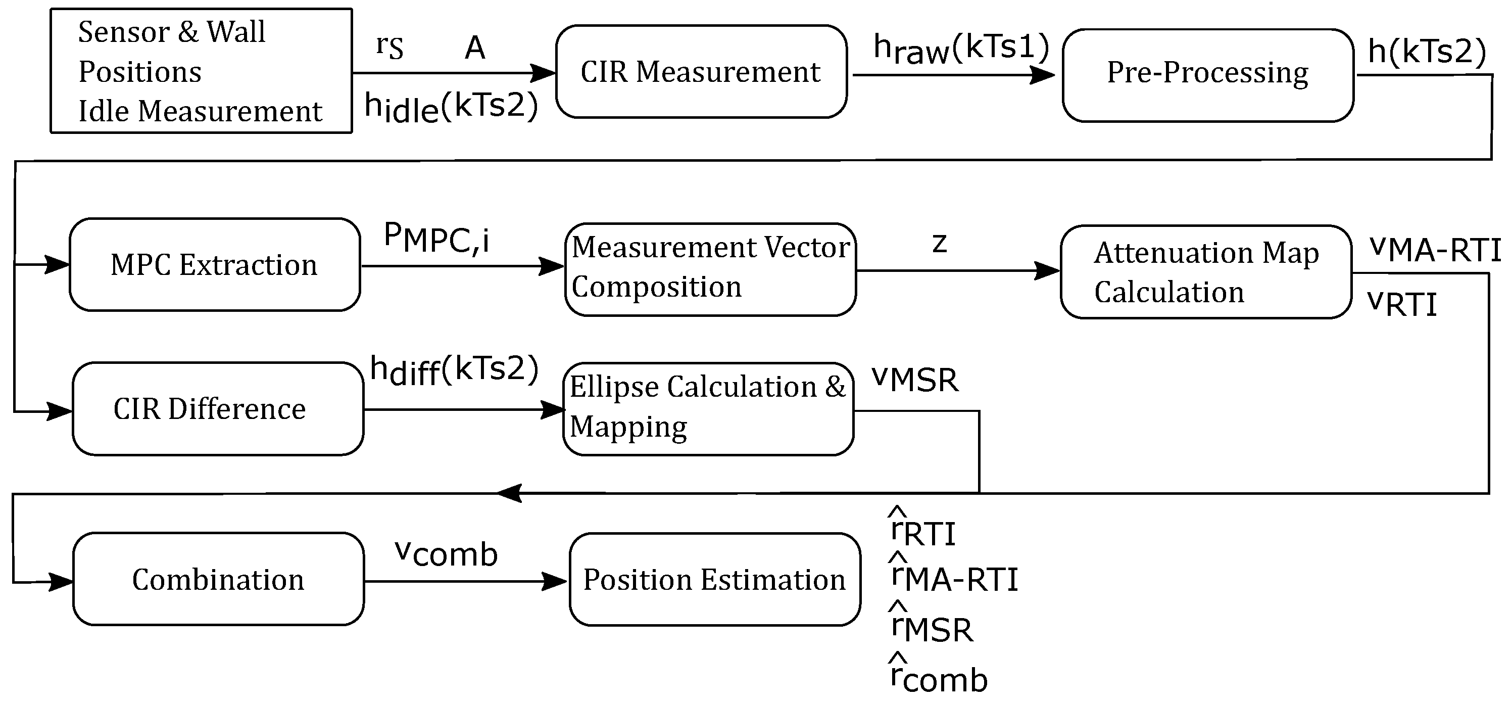
Figure 10 shows the flow chart of the algorithms we used in this paper. The initialization block requires information about the target area
A. That includes the physical sensor
and wall positions; furthermore, we recorded and pre-processed an idle UWB CIR measurement
, which is required for determining the absolute change of each MPC for MA-RTI and background subtraction for MSR.
For every position, or later in an online system, we acquire a CIR measurement , which is then pre-processed to , i.e., resampled, interpolated, and time aligned. After obtaining the observation, we calculate the results of the DFL methods. For MA-RTI, we extract the power magnitudes of the MPCs and compose the measurement vector z. After that, we calculate the heat map to obtain . For MSR, we perform the background subtraction and calculate the ellipses and map them unto the target area to obtain . Then, we calculate the combination of both methods . Finally, for each method, we obtain the most likely position and determine the localization error, which is defined in the upcoming section.
6. Conclusions and Future Work
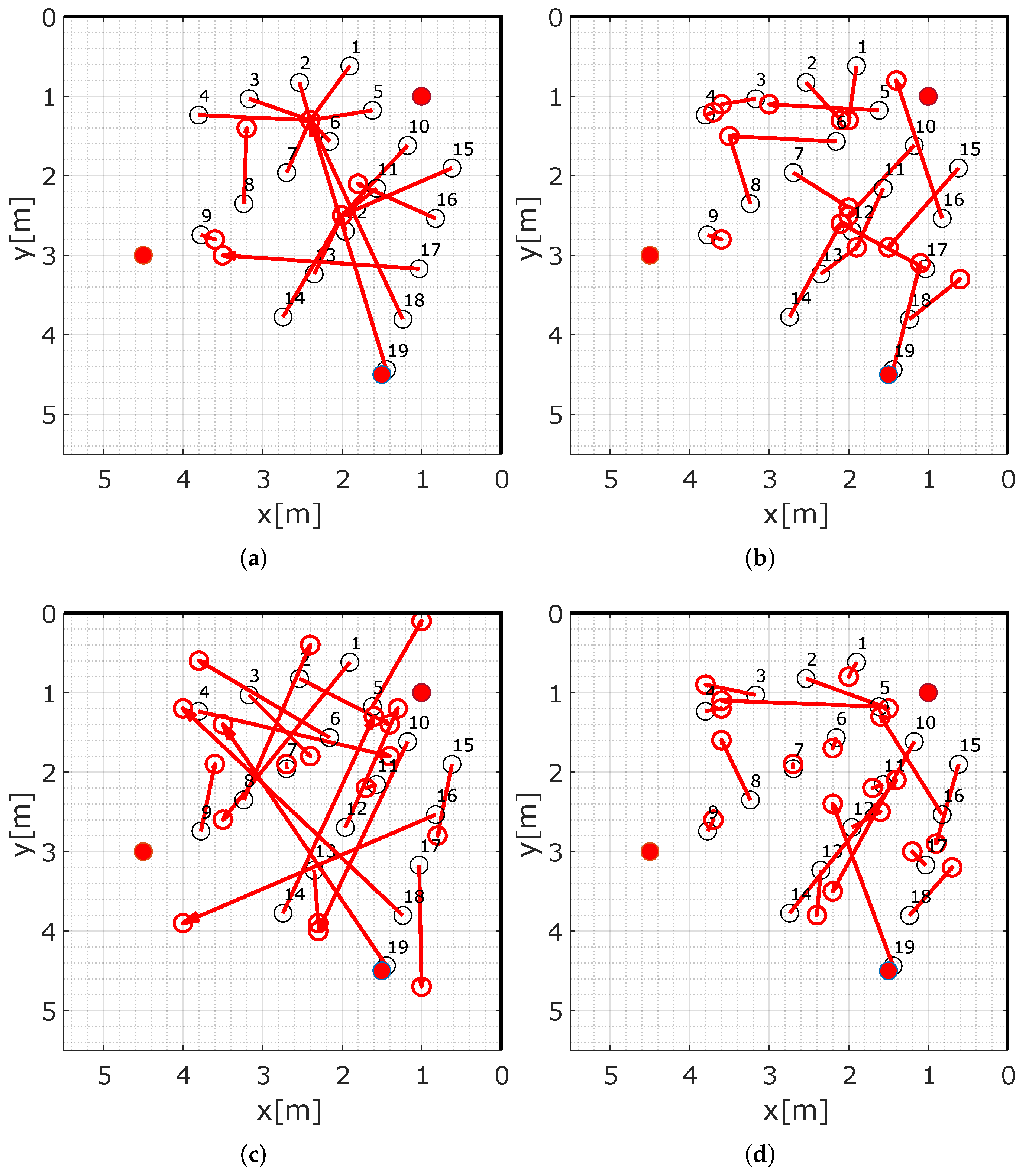
Two promising approaches for device-free localization (DFL) have been identified in the past: radio tomographic imaging (RTI) and multi-static radar (MSR). In this paper, we show how RTI benefits from the analysis of multipath propagation and show how MSR deals with multipath. We exploit the ultra-wideband (UWB) channel impulse response (CIR) measurements with four different DFL methods. To test and compare those DFL methods, we created a test setup with three sensor nodes and measured the UWB CIR with a commercially available off-the-shelf UWB radio chip, the Decawave DW1000. With our setup and 19 reference positions, we achieved the following results: RTI, which exploits the direct path without considering multipath in the CIR, results in a localization error of better than 0.84 m in 50% of all cases and in 1.5 m in 80% of all cases. Our proposed approach considering multipath effects MA-RTI results in a localization error of 0.82 m for 50% of the cases and in an error of 1.34 m for 80% of all cases. In comparison, MSR results in a localization error of 1.63 m (50% of the cases) and in an error of 2.72 m (80% of the cases). MSR performs worse, because the background subtraction applied to the measurement results does not compensate for all multipath propagation effects. Therefore, we propose a combination of MA-RTI and MSR that results in the best performance with a localization error of 0.64 m (50% of the cases) and 1.98 m (80% of the cases).
In the future, we will enhance the system and deploy it in an office-type indoor scenario. The indoor scenario will increase the effects of multipath, which can improve the localization results, if we manage to handle the complexity of the problem. Furthermore, we will implement a live system for evaluation and demonstration.


