Article

Design of a mmWave Antenna Printed on a Thick Vehicle-Glass Substrate Using a Linearly Arrayed Patch Director and a Grid-Slotted Patch Reflector for High-Gain Characteristics

1
Department of Electronic and Electrical Engineering, Hongik University, Seoul 04066, Korea
2
Department of Electrical Engineering, Ulsan National Institute of Science and Technology (UNIST), Ulsan 44919, Korea
*
Author to whom correspondence should be addressed.
Sensors 2022, 22(16), 6187; https://doi.org/10.3390/s22166187
Submission received: 21 July 2022 / Revised: 12 August 2022 / Accepted: 15 August 2022 / Published: 18 August 2022
(This article belongs to the Special Issue Antenna Design and Optimization for 5G, 6G, and IoT)

Abstract

:
This paper proposes a 5G glass antenna that can be printed on the thick window glass of a vehicle. The proposed antenna consists of a coplanar waveguide (CPW), a printed monopole radiator, parasitic elements, a linearly arrayed patch director, and a grid-slotted patch reflector. The linearly arrayed patch director and grid-slotted patch reflector are applied to improve the bore-sight gain of the antenna. To verify the performance improvement and feasibility, the proposed antenna is fabricated, and a reflection coefficient and a radiation pattern are measured and compared with the simulation results. The measured reflection coefficient shows broadband characteristics of less than −10 dB from 24.1 GHz to 31.0 GHz (fractional bandwidth of 24.6%), which agrees well with the simulation results. The reflection coefficients are −33.1 dB by measurement and −25.7 dB by simulation, and the maximum gains are 6.2 dBi and 5.5 dBi at 28 GHz, respectively. These results demonstrate that the proposed antenna has high-gain characteristics being suitable for 5G wireless communications.

1. Introduction

With the recent development of autonomous vehicle technologies, considerable efforts are devoted to employing 5G wireless communication systems for vehicle applications [1,2,3,4,5,6]. 5G vehicle wireless communication systems essentially require mmWave antennas that can stably maintain vehicle wireless communication links according to the signal transmission/reception environments while the vehicle is driving. To meet such requirements, many studies on the mmWave vehicle antennas have investigated by employing multiple antennas inside or outside vehicles [7,8,9,10,11,12], using a roof-top antenna for the coupling reduction with the vehicle body [13,14,15], and mounting the antennas inside the shark-fin radome [16,17]. These antennas have good impedance matching and high-gain characteristics for improving the reliability of 5G signal reception. However, it is difficult to practically use such antenna design techniques in vehicle applications because the change in the vehicle structures creates enormous costs in the vehicle manufacturing process. To resolve these problems, research on low-cost mmWave antennas that print various shapes such as a rectangular patch, a helical antenna, and a slot antenna on glass substrates, has been carried out [18,19,20]. Nevertheless, these antennas generally adopt thin glass substrates to reduce pattern distortion and radiation loss, and it is still difficult to apply them to thick glass substrates of actual vehicles. Although some mmWave antennas printed on very thick vehicle-glass substrates have been recently introduced, these vehicle-glass antennas generally exhibit low bore-sight gain characteristics [21,22,23].
In this paper, we propose an mmWave antenna printed on thick vehicle glass with a linearly arrayed patch director and a grid-slotted patch reflector for high-gain characteristics. The proposed antenna consists of a coplanar waveguide (CPW), a printed monopole radiator, parasitic elements, the linearly arrayed patch director, and the grid-slotted patch reflector. The monopole radiator with the parasitic elements is printed on the top surface of the thick vehicle glass. In addition, the linearly arrayed patch director is designed on the same surface with the monopole using seven rectangular patch elements to enhance the bore-sight gain. On the other side, the grid-slotted patch reflector, which consists of 5 × 4 rectangular patches, is printed to further improve the bore-sight gain and reduce the pattern distortion. This reflector can operate as a frequency selective surface (FSS), which reflects electromagnetic waves at a specific frequency [24,25]. The critical design parameters of the proposed antenna are then optimized using the CST Studio Suite EM simulation software [26] and re-validated by HFSS [27] and FEKO EM simulation software tool [28]. To verify the feasibility, it is fabricated and measured in a full anechoic chamber to obtain the antenna characteristics, such as reflection coefficients, gains, and radiation patterns. These results demonstrate that the proposed antenna on the thick vehicle glass has high-gain characteristics being suitable for 5G wireless communications.

2. Proposed Antenna Design

Figure 1 shows the geometry of the proposed on-glass antenna for the vehicle applications. The proposed antenna consists of a CPW transmission line, a printed monopole radiator, parasitic elements, a linearly arrayed patch director, and a grid-slotted patch reflector. Herein, the geometry and concept of the proposed antenna are modeled based on the previous research [23]. The CPW transmission line has an inner conductor with a length and a width of l1 and w4, and the rectangular grounds (l1 × w5) are designed on both sides of the inner line having a gap of g3. This CPW transmission line is printed on the top of a thick vehicle-glass substrate (εr = 6.9, tanδ = 0.03 at 28 GHz) having a thickness of t. Note that if the vehicle-glass substrate thickness becomes thicker, it is difficult to use the conventional monopole antenna due to performance degradations such as pattern distortion and gain reduction, which will be specifically discussed in Section 3. The CPW transmission line is usually less affected by the substrate thickness compared to other transmission lines (i.e., a microstrip line, a strip line, and a CPW with a ground), so that it is advantageous for use as a feeder in the proposed antenna employing the thick vehicle-glass substrate. The printed monopole radiator has a length of l3 and a width of w4 and is directly connected to the CPW inner conductor [29,30,31]. Four identical parasitic elements with a rectangular patch shape (l2 × w3) are located at distances of g2 from the CPW ground and g3 from the monopole radiator. The parasitic elements are indirectly coupled by electromagnetic fields from the monopole radiator, and surface current distributions near the parasitic elements can enlarge an effective aperture resulting in the improved radiation efficiency. On the same surface as the monopole and parasitic elements, seven rectangular patches having a width of w2 are linearly arrayed with an identical interval of g1 to model a director that can reduce the pattern distortion by focusing the electromagnetic fields at the bore-sight direction. The grid-slotted patch reflector with an M × N rectangular configuration is printed on the bottom of the thick vehicle-glass substrate, where M and N represent the number of reflector patches along the x- and y-axis, respectively. Each patch has a width w6 and an equal distance g4 between the adjacent patches, and the reflector can more improve the bore-sight gain by reflecting the back radiation field to make a constructive interference at the main lobe direction. The proposed antenna is modeled, and its critical design parameters are optimized using the CST Studio Suite EM simulator. The optimized parameters are listed in Table 1.

3. Analysis

Figure 2 presents the reflection coefficients according to the distance d from the end edge of the CPW ground to the starting edge of the grid-slotted patch reflector along the x-axis. The resonance of the proposed antenna can be adjusted by the overlapping area between the reflector and the printed monopole radiator with the parasitic elements, since the overlapping area can confine the strong electromagnetic fields inside the thick vehicle-glass substrate. Figure 3 illustrates the maximum gain and the main lobe direction θ0 in the upper hemisphere of the radiation pattern in accordance with a variation of d. The resulting maximum gain shows a peak level at the optimized distance of d = 1.06 mm, which allows the main lobe direction of θ0 to be approximately 0°.
Figure 4 shows the reflection coefficients according to the printed monopole length l3. The resonance frequency increases when l3 varies from 1.63 mm to 2.43 mm since the overlapping area between the printed monopole radiator and the reflector become larger.
To observe antenna characteristics according to the shape of the director, the bore-sight gain is simulated by changing the number of patch elements along the x- and y-axis, as shown in Figure 5. Lx and Ly specify the number of the patches in the x- and y-axis, respectively. High bore-sight gains are obtained when Lx is 1, which means the director is a linear array, and Ly of 7 is decided to have the maximum bore-sight gain of 5.5 dBi. Figure 6 shows the simulated bore-sight gains according to g1 and w2, while Lx and Ly are fixed to be 1 and 7. The bore-sight gains are examined in the parameter ranges of 0.1 mm ≤ g1 ≤ 1 mm and 1.5 mm ≤ w2 ≤ 2.5 mm. The peak gain of 5.5 dBi is obtained when the optimal values of g1 and w2 are 0.5 mm (0.125λ0) and 1.9 mm (0.48λ0), where λ0 is the wavelength at the operating frequency of 28 GHz.
Figure 7 illustrates the bore-sight gain in accordance with the gap (g4) and the width (w6) of the grid-slotted patch reflector. For a fixed M = 5 and N = 4, the bore-sight gain is observed in the ranges of 0.1 mm ≤ g4 ≤ 1 mm and 1.5 mm ≤ w6 ≤ 2.5 mm. Figure 8 shows the reflection coefficient and transmission coefficient of the grid-slotted patch reflector. The reflection coefficient is −1.7 dB, and the transmission coefficient is −10.1 dB at 28 GHz. These results mean that electromagnetic waves of 28 GHz are reflected well, thereby increasing the bore-sight gain [24,32,33].
Figure 9a,b present the maximum gain and the main lobe direction θ0 of the conventional printed monopole antenna in comparison with the proposed antenna according to the glass thickness t. For the conventional monopole antenna, the trends of the maximum gain and main lobe direction are considerably irregular. In particular, at a conventional vehicle glass thickness of 3.2 mm, θ0 is significantly tilted more than 150° from the bore-sight direction. On the other hand, for the proposed antenna, the main lobe direction θ0 is less than 10° in the range of 0.8 mm ≤ t ≤ 1.1 mm and 2.75 mm ≤ t ≤ 3.5 mm. In Figure 10, gain characteristics of the proposed antenna are observed according to variations of w1 from 2.5λ0 to 15λ0. The bore-sight gain fluctuates slightly when w1 is less than 5λ0, and it saturates to 4.5 dBi when w1 is more than 10λ0. The results confirm that the proposed antenna can be suitable for use in the large vehicle glass.

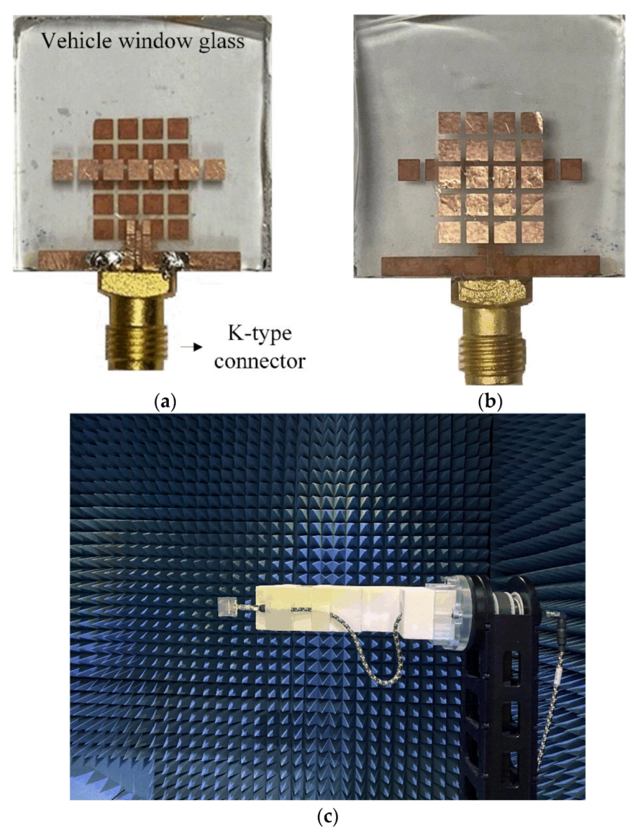
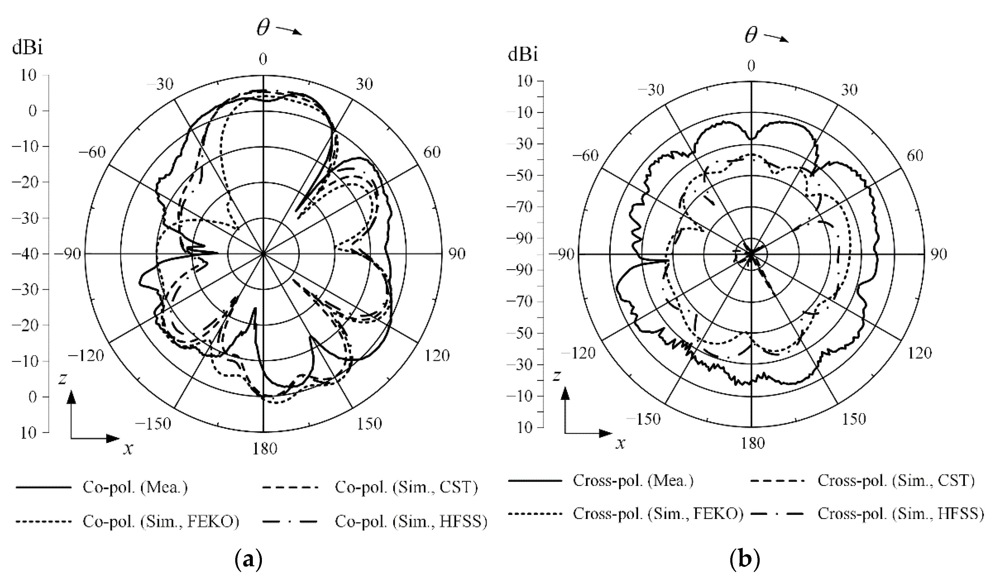
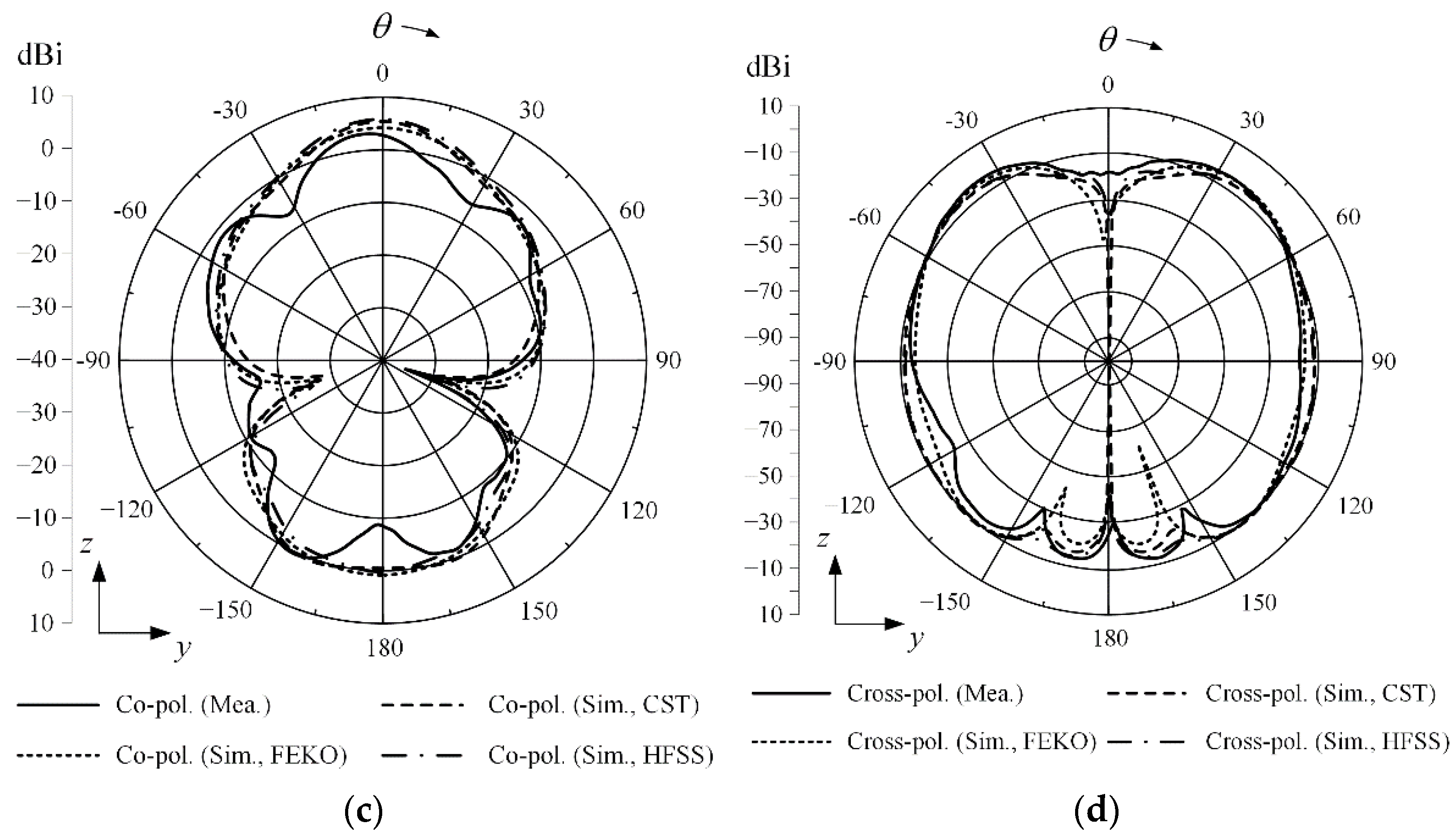
4. Fabrication and Measurement

Figure 11a,b shows the fabricated mmWave on-glass antenna with the linearly arrayed patch director and the grid-slotted patch reflector. The proposed antenna is fabricated using a thermosetting adhesive to strongly attach the printed antenna copper layers to the glass substrate. The proposed antenna is fed by a K-type (2.92 mm) connector operating at up to 40 GHz. The inner and outer conductors of the connector are electrically connected to the inner conductor and rectangular grounds of the CPW line by soldering. Figure 11c shows a photograph of the measurement setup, and antenna characteristics such as reflection coefficients and radiation patterns are measured in the full anechoic chamber.
As shown in Figure 12, the measured reflection coefficient shows broadband characteristics of less than −10 dB from 24.1 GHz to 31.0 GHz (fractional bandwidth of 24.6%), which agrees well with the simulation results. At 28 GHz, the measured reflection coefficient is −33.1 dB, while simulated reflection coefficients are −25.7 dB by CST, −23.8 dB by HFSS, and −27.9 dB by FEKO. Figure 13 illustrates maximum gains with or without the linearly arrayed patch director and the grid-slotted patch reflector. At 28 GHz, simulated result of the proposed antenna shows an improved maximum gain of 5.52 dBi. It is higher than the gain of 1.9 dBi without the reflector and the gain of 2.9 dBi without the director. The measurement results also agree well with the simulation, and the maximum measured gain is 6.20 dBi at 28 GHz. The radiation efficiency of the proposed antenna is 39%, which is higher than 31% without the reflector and 38% without the director.
Figure 14 shows the current distributions of the proposed antenna without the director and without the reflector. When the grid-slotted patch reflector is employed, the current distributions of the reflector are increased at 28 GHz.
Figure 15 shows two-dimensional (2-D) radiation patterns in zx- and zy-planes at 28 GHz. The measured maximum gain in the zx-plane is 6.20 dBi at θ = 14°, and the simulated maximum gain is 5.54 dBi at θ = −2° by CST. In the zy-plane, the measured maximum gain is 3.24 dBi at θ = −3°, and simulated result is 5.52 dBi at θ = 0° by CST. Figure 16 illustrates simulated 3-D radiation patterns according to the presence of the director and the reflector. The resulting 3-D radiation beam shapes obviously show that the bore-sight gain is improved by adding both the reflector and the director.

5. Conclusions

We proposed an mmWave on-glass antenna with a linearly arrayed patch director and a grid-slotted patch reflector. The proposed antenna was printed on the thick vehicle-glass substrate, which did not require the remodeling of the vehicle structures. To improve the bore-sight gain, the linearly arrayed patch director and the grid-slotted patch reflector were employed. The director and reflector were optimized to achieve high-gain characteristics on the thick glass substrate. The measured reflection coefficient of the proposed antenna was −33.1 dB, and the maximum gain was 6.2 dBi at 28 GHz. In addition, it was confirmed that the bore-sight gain was saturated to 4.5 dBi even when the size of the glass window was increased. Through the results, we verified that the proposed antenna achieving the high-gain characteristics could be suitable for 5G wireless communications.

Author Contributions

Conceptualization, C.I., T.H.L. and H.C.; methodology, C.I. and T.H.L.; software, C.I.; validation, C.I., T.H.L. and H.C.; formal analysis, C.I., T.H.L. and H.C.; investigation, C.I. and T.H.L.; resources, C.I.; data curation, C.I.; writing—original draft preparation, C.I., T.H.L. and H.C.; writing—review and editing, C.I., T.H.L. and H.C.; visualization, C.I.; supervision, H.C.; project administration, H.C.; funding acquisition, H.C. All authors have read and agreed to the published version of the manuscript.

Funding

This research was funded by the Basic Science Research Program through the National Research Foundation of Korea (NRF) funded by the Ministry of Education (no. NRF-2017R1A5A1015596), and the NRF grant funded by the Korea government (no. 2015R1A6A1A03031833).

Institutional Review Board Statement

Not applicable.

Informed Consent Statement

Not applicable.

Data Availability Statement

Not applicable.

Conflicts of Interest

The authors declare no conflict of interest.

References

  1. Minovski, D.; Åhlund, C.; Mitra, K. Modeling quality of IoT experience in autonomous vehicles. IEEE Internet Things J. 2020, 7, 3833–3849. [Google Scholar] [CrossRef]
  2. Wang, P.; Di, B.; Zhang, H.; Bian, K.; Song, L. Cellular V2X communications in unlicensed spectrum: Harmonious coexistence with VANET in 5G systems. IEEE Trans. Wirel. Commun. 2018, 17, 5212–5224. [Google Scholar] [CrossRef]
  3. Alalewi, A.; Dayoub, I.; Cherkaoui, S. On 5G-V2X use cases and enabling technologies: A comprehensive survey. IEEE Access 2021, 9, 107710–107737. [Google Scholar] [CrossRef]
  4. Lou, L.; Li, Q.; Zhang, Z.; Yang, R.; He, W. An IoT-driven vehicle detection method based on multisource data fusion technology for smart parking management system. IEEE Internet Things J. 2020, 7, 11020–11029. [Google Scholar] [CrossRef]
  5. Condoluci, M.; Gallo, L.; Mussot, L.; Kousaridas, A.; Spapis, P.; Mahlouji, M.; Mahmoodi, T. 5G V2X system-level architecture of 5GCAR project. Future Internet 2019, 11, 217. [Google Scholar] [CrossRef]
  6. Oh, S.S.; Choi, J.W.; Kim, D.W.; Lee, Y.C.; Cho, B.L. Comparison of 0.75–24-GHz reach distances and ratios using propagation path loss measurements from urban and rural line-of-sight environments. J. Electromagn. Eng. Sci. 2021, 21, 1–7. [Google Scholar] [CrossRef]
  7. Venkateswara Rao, M.; Madhav, B.T.P.; Krishna, J.; Usha Devi, Y.; Anilkumar, T.; Prudhvi Nadh, B. CSRR-loaded T-shaped MIMO antenna for 5G cellular networks and vehicular communications. Int. J. RF Microw. Comput. Aid. Eng. 2019, 29, e21799. [Google Scholar] [CrossRef]
  8. Devi, Y.U.; Rukmini, M.S.S.; Madhav, B.T.P. Liquid crystal polymer based flexible and conformal 5G antenna for vehicular communication. Mater. Res. Express. 2018, 6, 016306. [Google Scholar] [CrossRef]
  9. Feng, B.; Chen, J.; Yin, S.; Sim, C.-Y.-D.; Zhao, Z. A tri-polarized antenna with diverse radiation characteristics for 5G and V2X communications. IEEE Trans. Veh. Technol. 2020, 69, 10115–10126. [Google Scholar] [CrossRef]
  10. Cheng, Y.; Lu, J.; Wang, C. Design of a multiple band vehicle-mounted antenna. Int. J. Antennas Propag. 2019, 2019, 11. [Google Scholar] [CrossRef]
  11. Sun, Y.-X.; Leung, K.W.; Lu, K. Compact dual microwave/millimeter-wave planar shared-aperture antenna for vehicle-to-vehicle/5G Communications. IEEE Trans. Veh. Technol. 2021, 70, 5071–5076. [Google Scholar] [CrossRef]
  12. Awan, W.A.; Naqvi, S.I.; Naqvi, A.H.; Abbas, S.M.; Zaidi, A.; Hussain, N. Design and characterization of wideband printed antenna based on DGS for 28 GHz 5G applications. J. Electromagn. Eng. Sci. 2021, 21, 177–183. [Google Scholar] [CrossRef]
  13. Artner, G.; Kotterman, W.; Galdo, G.D.; Hein, M.A. Conformal automotive roof-top antenna cavity with increased coverage to vulnerable road users. IEEE Antennas Wirel. Propag. Lett. 2018, 17, 2399–2403. [Google Scholar] [CrossRef]
  14. Artner, G.; Langwieser, R.; Mecklenbrauker, C.F. Concealed CFRP vehicle chassis antenna cavity. IEEE Antennas Wirel. Propag. Lett. 2017, 16, 1415–1418. [Google Scholar] [CrossRef]
  15. Artner, G.; Kotterman, W.; Galdo, G.D.; Hein, M.A. Automotive antenna roof for cooperative connected driving. IEEE Access 2019, 7, 20083–20090. [Google Scholar] [CrossRef]
  16. Khalifa, M.O.; Yacoub, A.M.; Aloi, D.N. A multiwideband compact antenna design for vehicular sub-6 GHz 5G wireless systems. IEEE Trans. Antennas Propag. 2021, 69, 8136–8142. [Google Scholar] [CrossRef]
  17. Yacoub, A.M.; Khalifa, M.O.; Aloi, D.N. Wide band raised printed monopole for automotive 5G wireless communications. IEEE Antennas Propag. Mag. 2022, 3, 502–510. [Google Scholar] [CrossRef]
  18. Goyal, R.; Vishwakarma, D.K. Design of a graphene-based patch antenna on glass substrate for high-speed terahertz communications. Microw. Opt. Technol. Lett. 2018, 60, 1594–1600. [Google Scholar] [CrossRef]
  19. Naqvi, A.H.; Park, J.; Baek, C.; Lim, S. V-Band end-fire radiating planar micromachined helical antenna using through-glass silicon via (TGSV) technology. IEEE Access 2019, 7, 87907–87915. [Google Scholar] [CrossRef]
  20. Cil, E.; Dumanli, S. The design of a reconfigurable slot antenna printed on glass for wearable applications. IEEE Access 2020, 8, 95417–95423. [Google Scholar] [CrossRef]
  21. Jang, D.; Kong, N.K.; Choo, H. Design of an on-glass 5G monopole antenna for a vehicle window glass. IEEE Access 2021, 9, 152749–152755. [Google Scholar] [CrossRef]
  22. Youn, S.; Jang, D.; Kong, N.K.; Choo, H. Design of a printed 5G monopole antenna with periodic patch director on the laminated window glass. IEEE Antennas Wirel. Propag. Lett. 2022, 21, 297–301. [Google Scholar] [CrossRef]
  23. Im, C.; Lim, T.-H.; Jang, D.; Kong, N.-K.; Choo, H. Design of a printed 5G monopole antenna on vehicle window glass using parasitic elements and a lattice-structure reflector for gain enhancement. Appl. Sci. 2021, 11, 9953. [Google Scholar] [CrossRef]
  24. Alwareth, H.; Ibrahim, I.M.; Zakaria, Z.; Al-Gburi, A.J.A.; Ahmed, S.; Nasser, Z.A. A wideband high-gain microstrip array antenna integrated with frequency-selective surface for Sub-6 GHz 5G applications. Micromachines 2022, 13, 1215. [Google Scholar] [CrossRef]
  25. Mohyuddin, W.; Kim, D.H.; Choi, H.C.; Kim, K.W. Comparative study of square and circular loop frequency selective surfaces for millimeter-wave imaging diagnostics systems. Sensors 2018, 18, 3079. [Google Scholar] [CrossRef]
  26. CST Microwave Studio. Available online: http://www.cst.com (accessed on 10 October 2021).
  27. Available online: http://www.ansys.com/products/electronics/ansys-hfss (accessed on 30 July 2019).
  28. Altair. FEKO. Available online: http://www.altair.com (accessed on 29 March 2022).
  29. Pan, C.-Y.; Horng, T.-S.; Chen, W.-S.; Huang, C.-H. Dual wideband printed monopole antenna for WLAN/WiMAX applications. IEEE Antennas Wirel. Propag. Lett. 2007, 6, 149–151. [Google Scholar] [CrossRef]
  30. Ahmed, O.; Sebak, A. A printed monopole antenna with two steps and a circular slot for UWB applications. IEEE Antennas Wirel. Propag. Lett. 2008, 7, 411–413. [Google Scholar] [CrossRef]
  31. Kuo, Y.-L.; Wong, K.-L. Printed double-T monopole antenna for 2.4/5.2 GHz dual-band WLAN operations. IEEE Trans. Antennas Propag. 2003, 51, 2187–2192. [Google Scholar]
  32. Chatterjee, A.; Parui, S.K. Performance enhancement of a dual-band monopole antenna by using a frequency-selective surface-based corner reflector. IEEE Trans. Antennas Propag. 2016, 64, 2165–2171. [Google Scholar] [CrossRef]
  33. Ranga, Y.; Matekovits, L.; Esselle, K.P.; Weily, A.R. Multioctave frequency selective surface reflector for ultrawideband antennas. IEEE Antennas Wirel. Propag. Lett. 2011, 10, 219–222. [Google Scholar] [CrossRef]
Figure 1. Geometry of the proposed antenna: (a) isometric view; (b) top view; (c) bottom view; (d) side view.
Sensors 22 06187 g001
Figure 2. Reflection coefficients in accordance with the parameter d.
Sensors 22 06187 g002
Figure 3. The maximum gain and main lobe direction θ0 in accordance with the parameter d at 28 GHz.
Sensors 22 06187 g003
Figure 4. Reflection coefficients in accordance with the parameter l3.
Sensors 22 06187 g004
Figure 5. Bore-sight gain in accordance with the number of patch elements in the director.
Sensors 22 06187 g005
Figure 6. Bore-sight gain in accordance with parameters g1 and w2.
Sensors 22 06187 g006
Figure 7. Bore-sight gain in accordance with parameters g4 and w6.
Sensors 22 06187 g007
Figure 8. Reflection coefficient and transmission coefficient of the grid-slotted patch reflector.
Sensors 22 06187 g008
Figure 9. The maximum gain and main lobe direction θ0 in accordance with parameter t: (a) conventional printed monopole antenna; (b) proposed antenna.
Sensors 22 06187 g009aSensors 22 06187 g009b
Figure 10. Bore-sight gain in accordance with the parameter w1.
Sensors 22 06187 g010
Figure 11. Photographs of the proposed antenna and measurement setup: (a) top view; (b) bottom view; (c) measurement setup.
Sensors 22 06187 g011
Figure 12. Measured and simulated reflection coefficients of the proposed antenna.
Sensors 22 06187 g012
Figure 13. Maximum gains with and without the director and the reflector.
Sensors 22 06187 g013
Figure 14. Current distributions: (a) proposed antenna; (b) without the director; (c) without the reflector.
Sensors 22 06187 g014aSensors 22 06187 g014b
Figure 15. Measured and simulated 2-D radiation patterns of the proposed antenna at 28 GHz: (a) zx-plane co-polarization; (b) zx-plane cross-polarization; (c) zy-plane co-polarization; (d) zy-plane cross-polarization.
Sensors 22 06187 g015aSensors 22 06187 g015b
Figure 16. 3-D radiation patterns by simulation: (a) proposed antenna; (b) without the director; (c) without the reflector.
Sensors 22 06187 g016aSensors 22 06187 g016b
Table 1. Design parameters of the proposed antenna.
ParametersValuesParametersValues
w125 mmg10.5 mm
w22 mmg20.13 mm
w30.8 mmg30.13 mm
w40.5 mmg40.5 mm
w59.62 mmd1.06 mm
w62 mmL7
l12 mmM5
l21.4 mmN4
l32.03 mmt3.2 mm
Publisher’s Note: MDPI stays neutral with regard to jurisdictional claims in published maps and institutional affiliations.

