
Positioning and Tracking of Multiple Humans Moving in Small Rooms Based on a One-Transmitter–Two-Receiver UWB Radar Configuration


Abstract
:1. Introduction
2. Materials and Methods
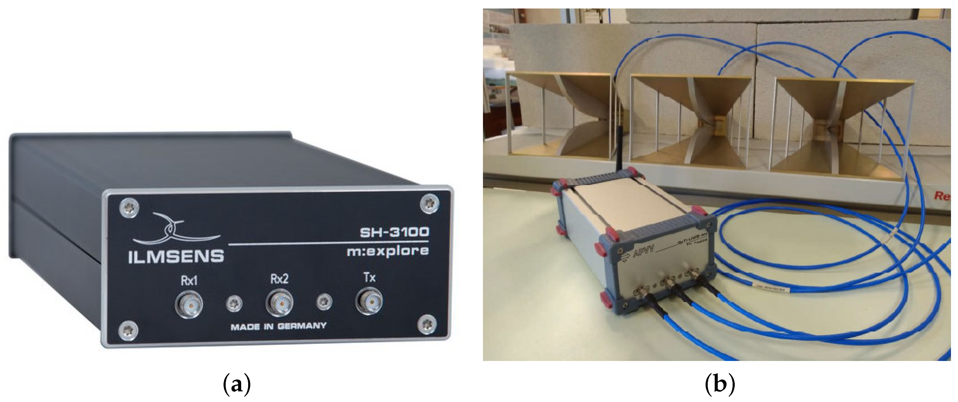
2.1. M:Explore—The Newest Version of M-Sequence UWB Radar
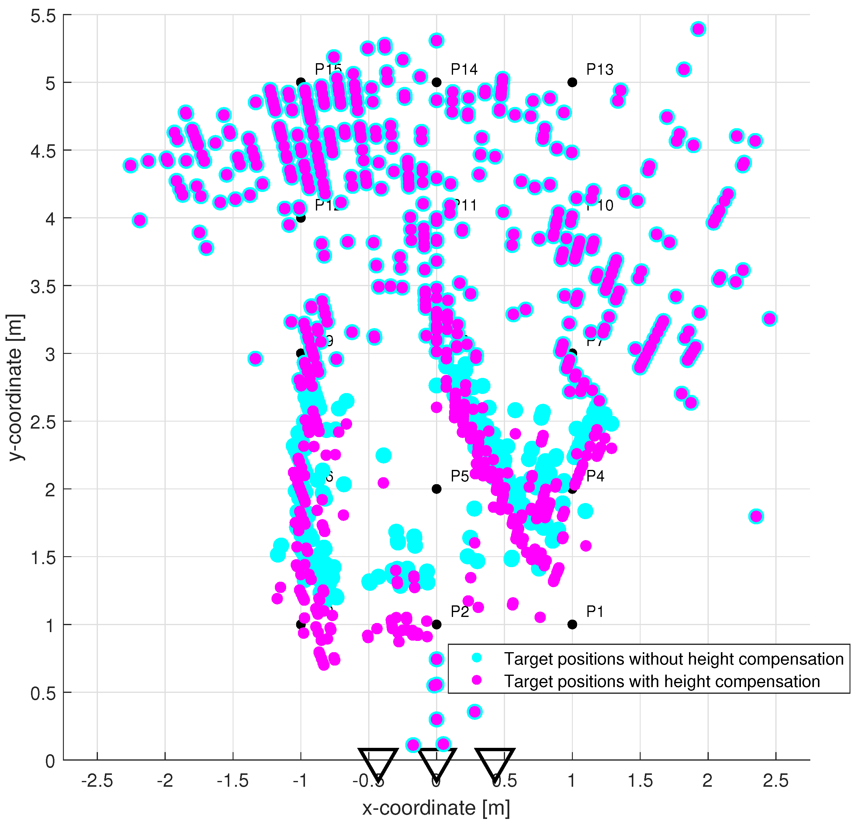
2.2. Contribution of the High Set-Up of the Radar Antennas
2.3. Signal Processing Methods Enabling Real-Time Tracking of Multiple Moving Human Targets
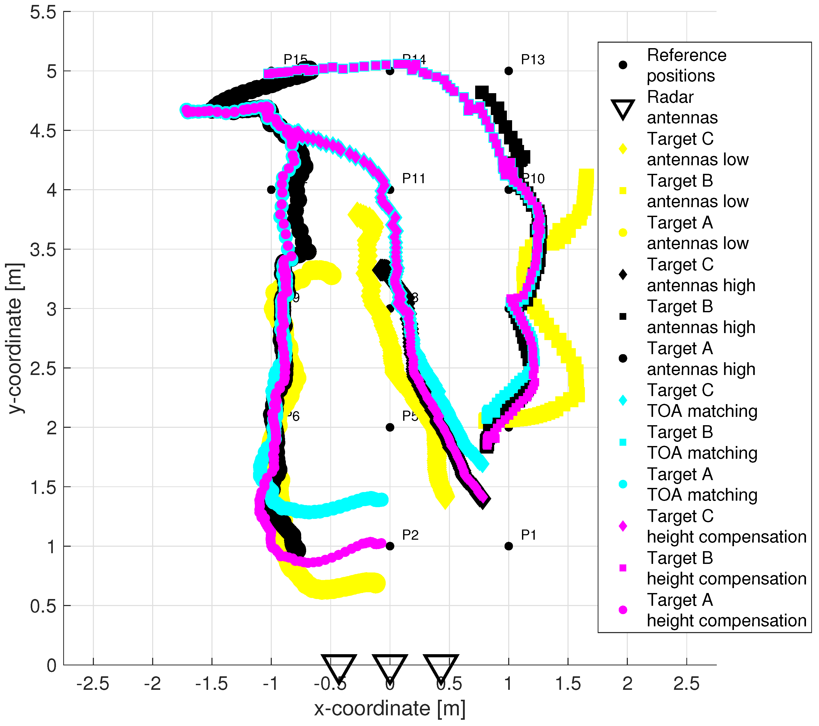
2.3.1. TOA Matching Method
- Step 1
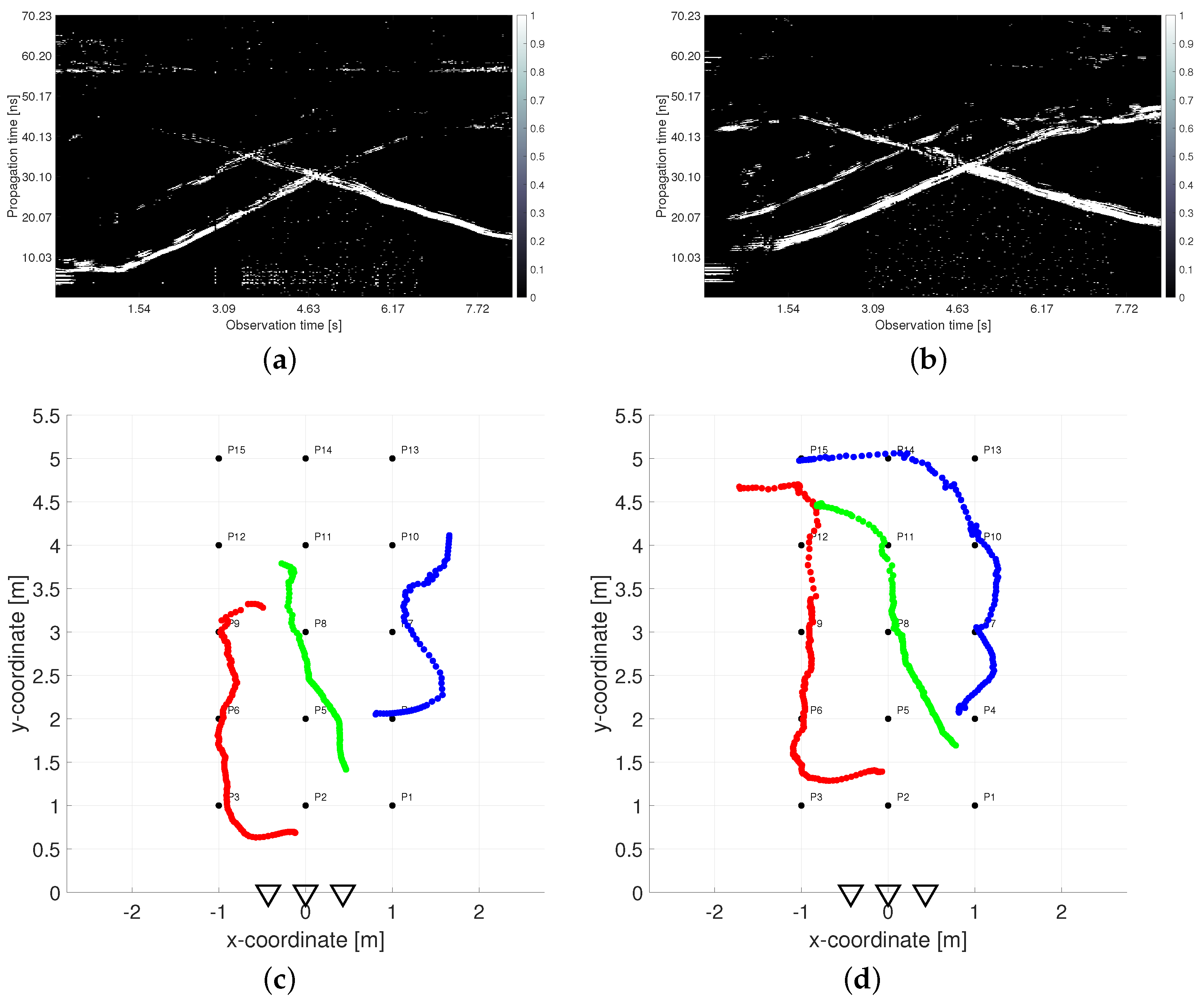
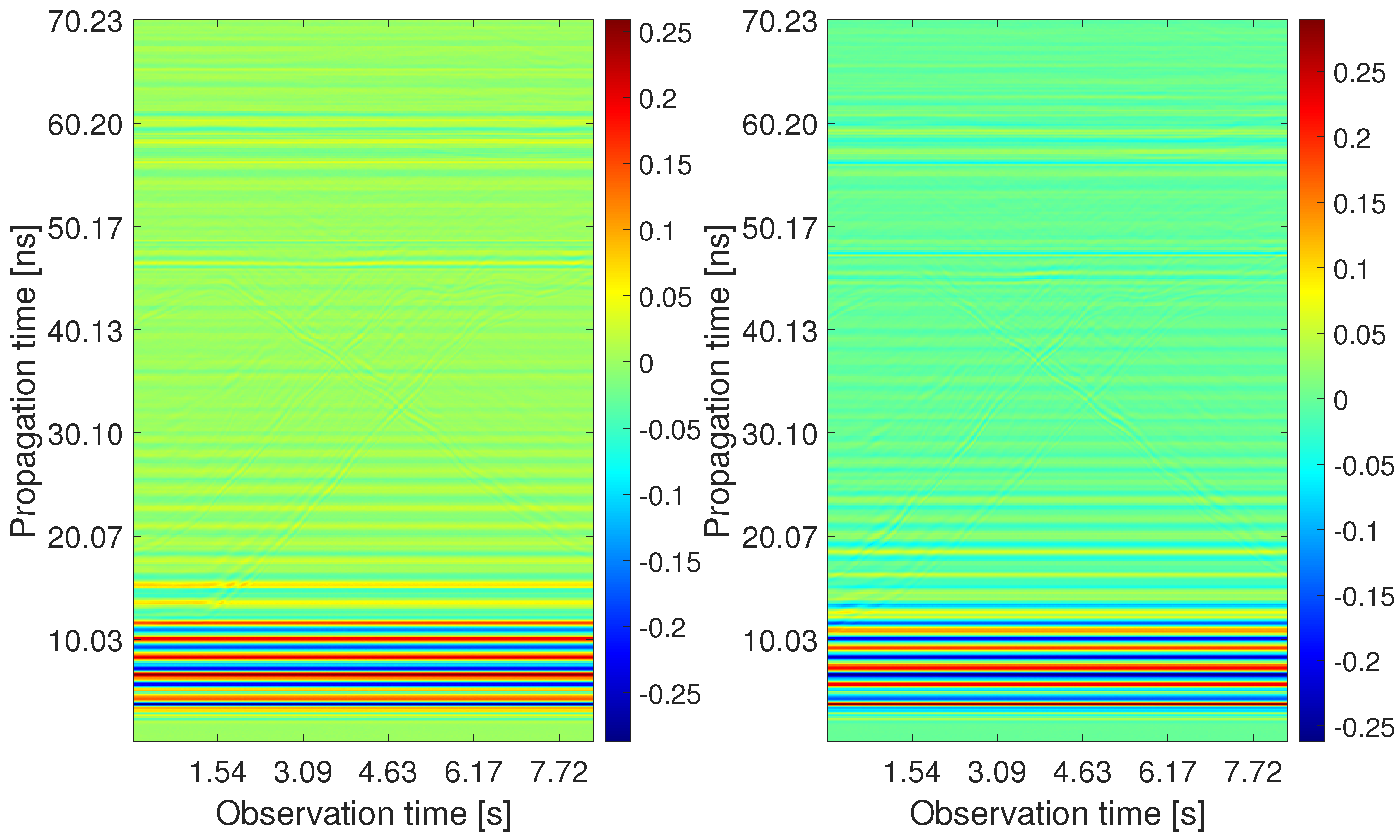
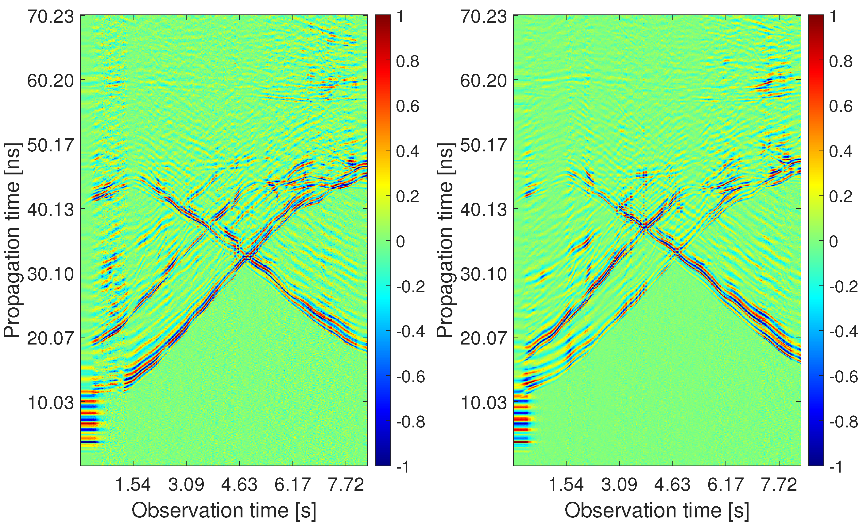
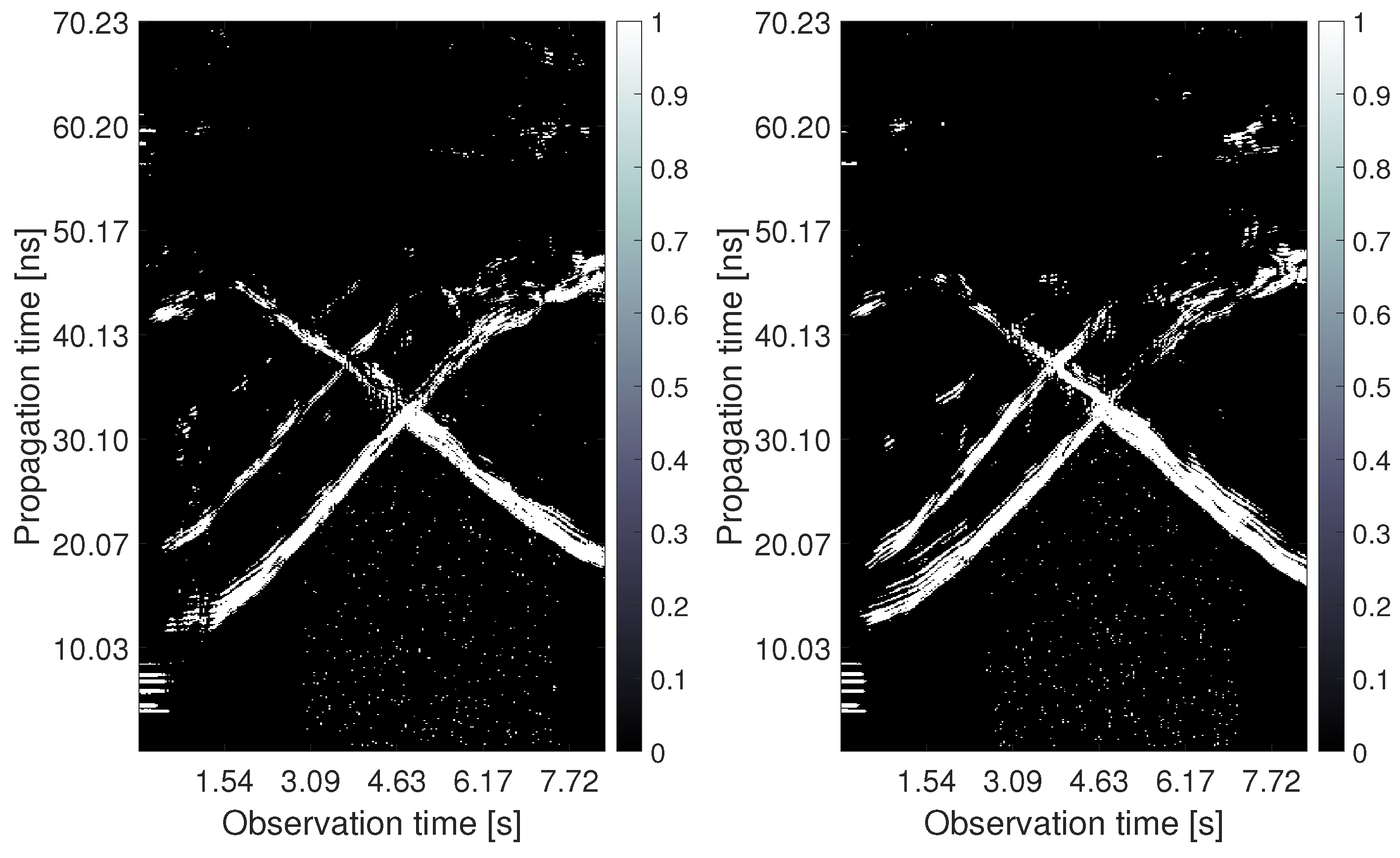
- Summation of detector output with an interval length corresponding to the assumed size of a targetThe goal of the first two steps of the method is to eliminate the false alarms and complete the detection outputs where the target should be detected, but it has not been. The used CFAR detector produces the input data for this stage in the form of a complex binary sequence (see e.g., the columns in Figure 3a,b). The multiple reflections of electromagnetic waves from the targets and the false alarms create the set of non-zero samples. As the target size is much bigger than the radar resolution and by taking into account different shapes and properties of the human body surface, the radar echo is usually represented by clusters with a higher concentration of “1” samples. The length of such clusters is estimated by the parameter. In rough approximation, it corresponds to a target size expressed in the number of samples of an impulse response according to the known radar resolution. However, if a multi-target presence is expected, a much lower value is recommended to separate their echos.
- Step 2
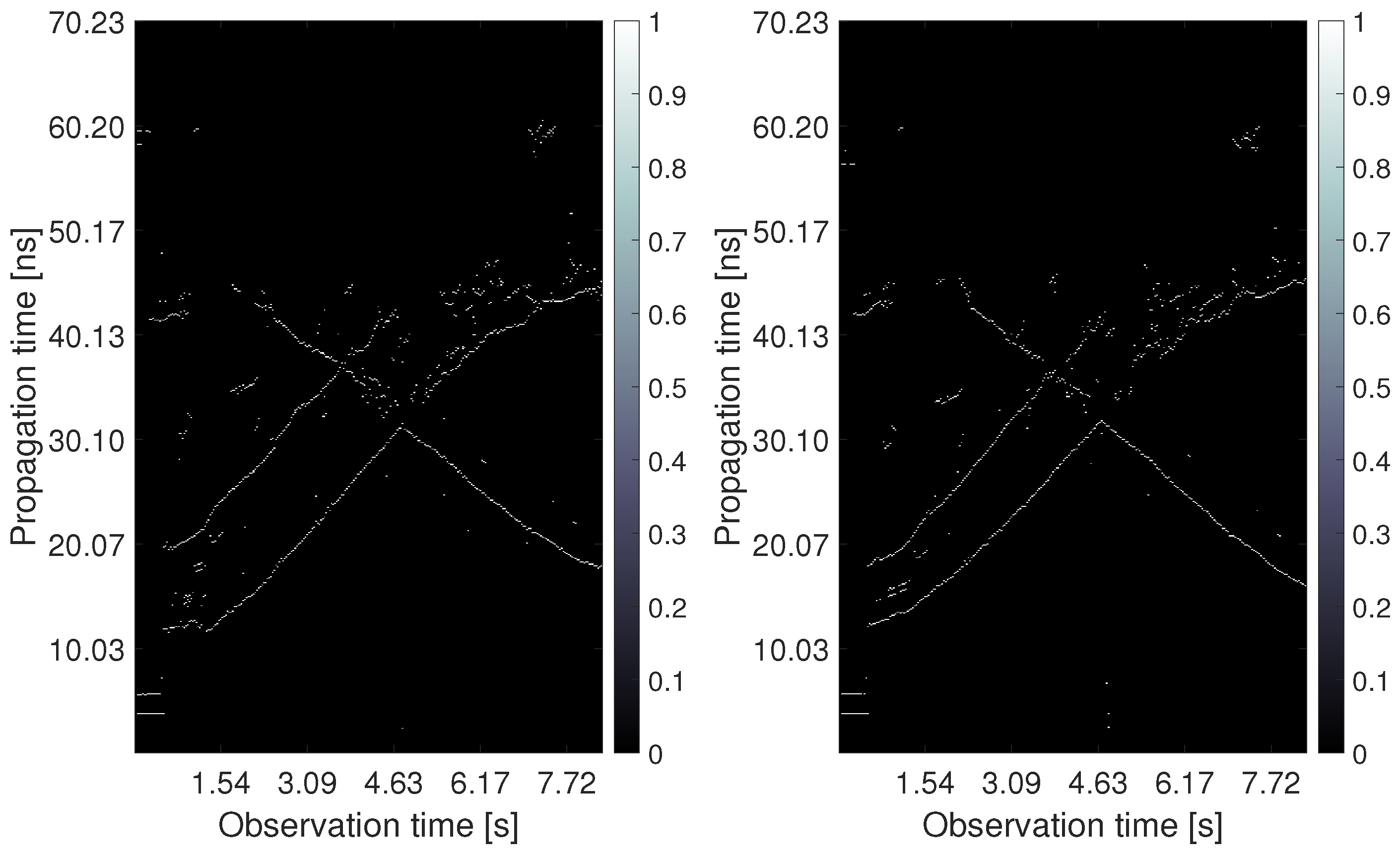
- Generation of continuous TOA intervals within which the targets are detectedBy comparison of the summation from Step 1 with parameter, continuous TOA intervals for every extended target are generated. This parameter determines the minimal number of reflections in a given summation. The higher the value, the bigger the number of false alarms that are suppressed. On the other hand, the weak reflections from targets can be lost, too. As the pointed targets improperly indicated by the false alarm clusters are considerably reduced during the association phase, we recommend a smaller parameter setting.
- Step 3
- Substitution of extended targets by simple targetsIn this step, every continuous TOA interval is substituted by only one TOA (only one propagation time instant) representing the TOA of a potential simple target. As we suggest that the antennas be placed at a higher height during the measurement, usually, the first reflections from a moving person are from the head and shoulders and the last reflections come from the feet or are caused by multiple reflections from the floor. The TOA matching method enables to choose as point representation of the extended target, the first, middle, or the last sample of every continuous TOA interval moved in such a way to fit with the beginning of the original cluster of detected non-zero samples. As the width of the continuous TOA intervals depends on the distance of the target to the radar antennas, the positioning based on the middle or the last TOA causes a bigger localization error in the farther distances. Therefore we recommend using the first sample of continuous TOA interval as a potential simple target representation that corresponds with the leading edge of the target detection.
- Step 4
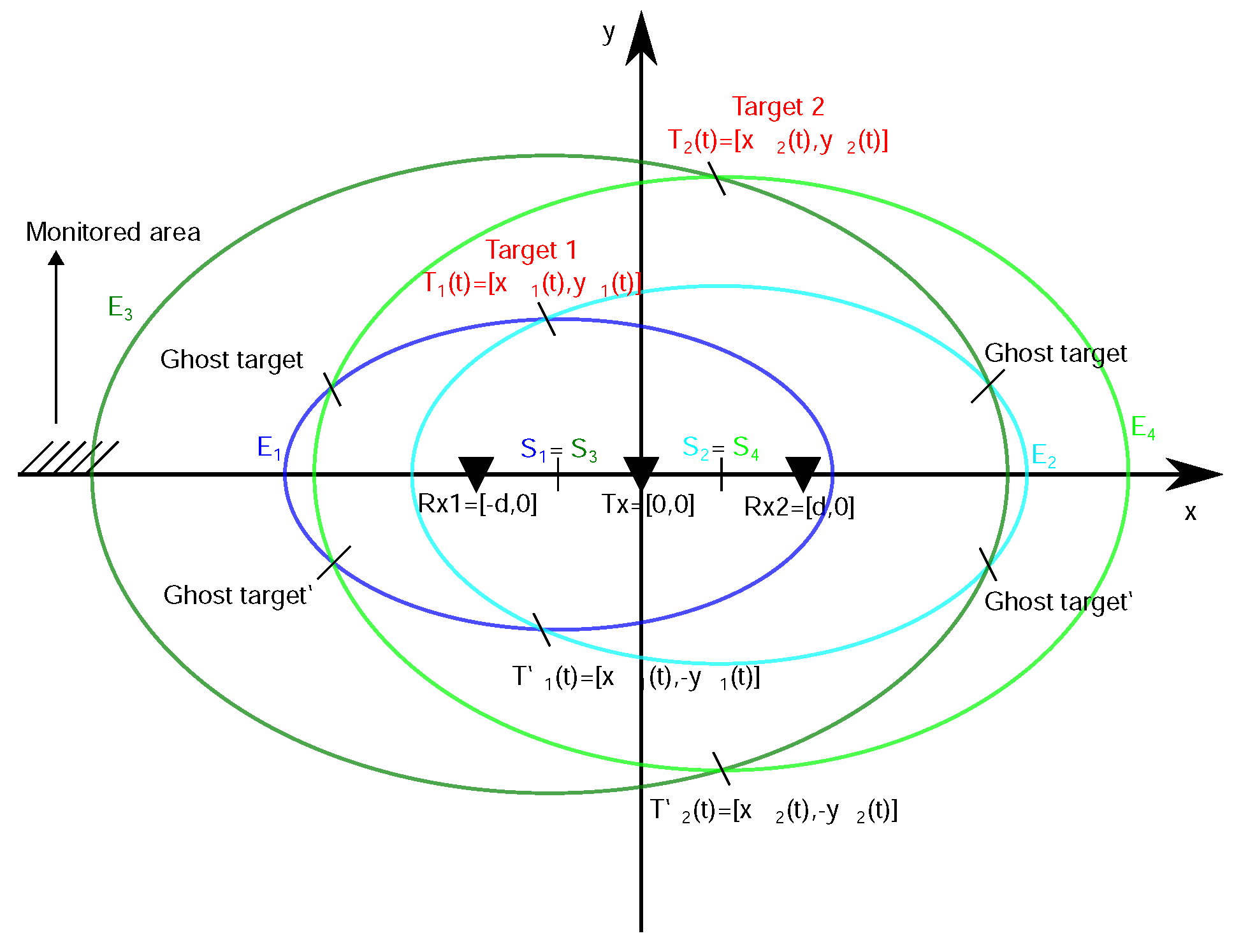
- Creation of all potential TOA pairs that meet a matching conditionThe association phase of the proposed approach solves the task of recognizing all couples of TOA estimated from both receivers in such a way that they produce, after the localization process, the true target positions and not the ghost targets. The main idea consists of the utilization of known and short distance d between adjacent antennas and results in an exactly computable and small difference between TOA estimated from both receivers (, ) and belonging to the same single target j. The difference is calculated based on the triangle inequality arising from the antenna layout and an arbitrary target position [52] and is labeled hereinafter as the matching condition:where corresponds to the simple TOA estimated from the for the j-th target, , and c represents a light speed. The smaller the distance d between the antennas, the clearer the association between nearby targets. However, too small d worsens positioning accuracy [51].
- Step 5
- Completion of traces based on TOA couples found in the previous time observation instantThis step enables completion of the potential couple of TOA by the missing TOA if only one receiving channel has detected a target echo. It is based on confirmed TOA couples found in the previous time observation instant similarly to the trace connection method. However, now the missing TOA in the actual instant is computed according to the known difference between associated TOA from the previous instant unlike simple repeating of the last known TOA.
2.3.2. Antennas Height Compensation Method
2.3.3. Trilateration Principle for a Bistatic Radar with One Tx-Two Rx Configuration
3. Results
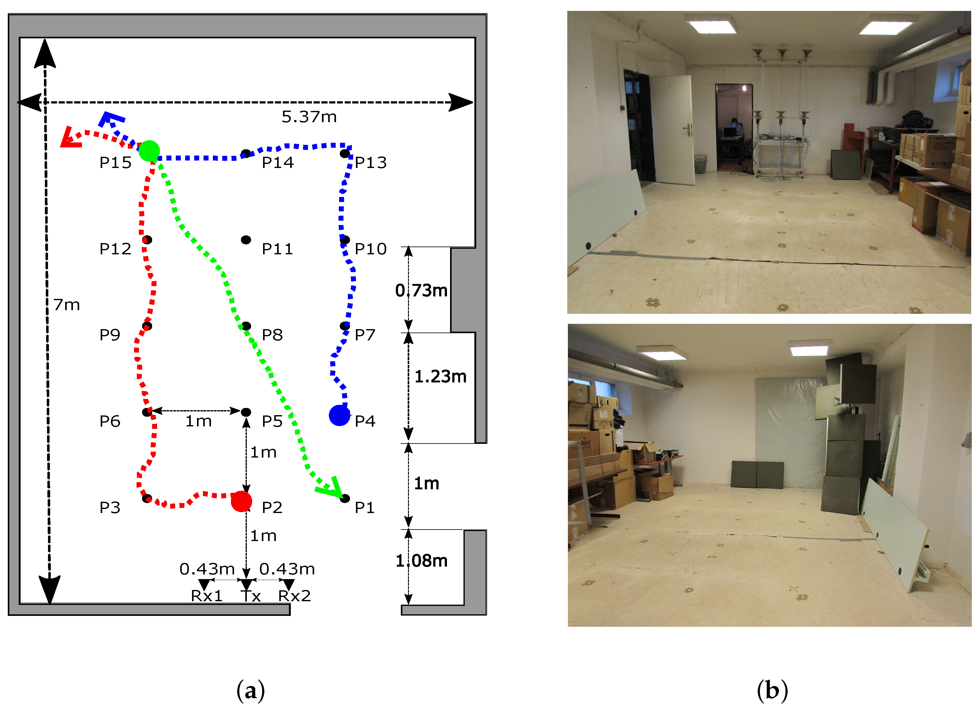
3.1. Parameters
3.2. Qualitative Analysis
3.3. Quantitative Analysis
4. Discussion
Author Contributions
Funding
Informed Consent Statement
Data Availability Statement
Conflicts of Interest
References
- Yarovoy, A.; Zhuge, X.; Savelyev, T.; Ligthart, L. Comparison of UWB technologies for human being detection with radar. In Proceedings of the 2007 European Microwave Conference, Munich, Germany, 9–12 October 2007; pp. 1574–1577. [Google Scholar]
- Khan, F.; Ghaffar, A.; Khan, N.; Cho, S.H. An overview of signal processing techniques for remote health monitoring using impulse radio UWB transceiver. Sensors 2020, 20, 2479. [Google Scholar] [CrossRef] [PubMed]
- Kebe, M.; Gadhafi, R.; Mohammad, B.; Sanduleanu, M.; Saleh, H.; Al-Qutayri, M. Human vital signs detection methods and potential using radars: A review. Sensors 2020, 20, 1454. [Google Scholar] [CrossRef] [PubMed] [Green Version]
- Zhang, Y.; Qi, F.; Lv, H.; Liang, F.; Wang, J. Bioradar technology: Recent research and advancements. IEEE Microw. Mag. 2019, 20, 58–73. [Google Scholar] [CrossRef]
- Thi Phuoc Van, N.; Tang, L.; Demir, V.; Hasan, S.F.; Duc Minh, N.; Mukhopadhyay, S. Microwave radar sensing systems for search and rescue purposes. Sensors 2019, 19, 2879. [Google Scholar] [CrossRef] [PubMed] [Green Version]
- Kocur, D.; Švecová, M.; Zetik, R. Basic signal processing principles for monitoring of persons using UWB sensors—An overview. Acta Electrotech. Inform. 2019, 19, 9–15. [Google Scholar] [CrossRef]
- Yang, D.; Zhu, Z.; Zhang, J.; Liang, B. The overview of human localization and vital sign signal measurement using handheld IR-UWB through-wall radar. Sensors 2021, 21, 402. [Google Scholar] [CrossRef]
- Li, C.; Peng, Z.; Huang, T.Y.; Fan, T.; Wang, F.K.; Horng, T.S.; Munoz-Ferreras, J.M.; Gomez-Garcia, R.; Ran, L.; Lin, J. A review on recent progress of portable short-range noncontact microwave radar systems. IEEE Trans. Microw. Theory Tech. 2017, 65, 1692–1706. [Google Scholar] [CrossRef]
- Borek, S.E. An overview of through the wall surveillance for homeland security. In Proceedings of the 34th Applied Imagery and Pattern Recognition Workshop (AIPR’05), Washington, DC, USA, 19 October–21 December 2005; p. 6. [Google Scholar]
- Yılmaz, B.; Özdemir, C. A detection and localization algorithm for moving targets behind walls based on one transmitter-two receiver configuration. Microw. Opt. Technol. Lett. 2017, 59, 1252–1259. [Google Scholar] [CrossRef]
- Nguyen, V.H.; Pyun, J.Y. Location detection and tracking of moving targets by a 2D IR-UWB radar system. Sensors 2015, 15, 6740–6762. [Google Scholar] [CrossRef] [Green Version]
- Wu, S.; Meng, S.; Chen, J. The detection and localization of targets in 2D or 3D scene using ultra-wideband short-pulse through-the-wall radar. In Proceedings of the MIPPR 2009: Multispectral Image Acquisition and Processing, Yichang, China, 30 October–1 November 2009; SPIE: Bellingham, WA, USA, 2009; Volume 7494, pp. 344–351. [Google Scholar]
- Yoo, S.; Wang, D.; Seol, D.M.; Lee, C.; Chung, S.; Cho, S.H. A multiple target positioning and tracking system behind brick-concrete walls using multiple monostatic IR-UWB radars. Sensors 2019, 19, 4033. [Google Scholar] [CrossRef] [Green Version]
- Zetik, R.; Crabbe, S.; Krajnak, J.; Peyerl, P.; Sachs, J.; Thomä, R. Detection and localization of persons behind obstacles using M-sequence through-the-wall radar. In Proceedings of the Sensors, and Command, Control, Communications, and Intelligence (C3I) Technologies for Homeland Security and Homeland Defense V, Orlando, FL, USA, 17–21 April 2006; International Society for Optics and Photonics: Bellingham, WA, USA, 2006; Volume 6201, p. 62010I. [Google Scholar]
- Antonucci, A.; Corrà, M.; Ferrari, A.; Fontanelli, D.; Fusari, E.; Macii, D.; Palopoli, L. Performance analysis of a 60-GHz radar for indoor positioning and tracking. In Proceedings of the 2019 International Conference on Indoor Positioning and Indoor Navigation (IPIN), Pisa, Italy, 30 September–3 October 2019; pp. 1–7. [Google Scholar]
- Kocur, D.; Fortes, J.; Švecová, M. Multiple moving person tracking by UWB sensors: The effect of mutual shielding persons and methods reducing its impacts. EURASIP J. Wirel. Commun. Netw. 2017, 2017, 68. [Google Scholar] [CrossRef] [Green Version]
- Zhang, J.; Jin, T.; He, Y.; Zhou, Z. A Centralized Processing Framework for Foliage-Penetration Human Tracking in Multistatic Radar. Radioengineering 2016, 25, 98–105. [Google Scholar] [CrossRef]
- He, Y. Human Target Tracking in Multistatic Ultra-Wideband Radar. Ph.D. Thesis, Delft University of Technology, Delft, The Netherland, 2014. [Google Scholar]
- Zhang, J.; Jin, T.; He, Y.; Qiu, L.; Zhou, Z. Range–Doppler-based centralised framework for human target tracking in multistatic radar. IET Radar Sonar Navig. 2017, 11, 193–203. [Google Scholar] [CrossRef]
- Rovňáková, J.; Kocur, D. Short range tracking of moving persons by UWB sensor network. In Proceedings of the 2011 8th European Radar Conference, Manchester, UK, 12–14 October 2011; pp. 321–324. [Google Scholar]
- Zetik, R.; Jovanoska, S.; Thomä, R. Simple method for localisation of multiple tag-free targets using UWB sensor network. In Proceedings of the 2011 IEEE International Conference on Ultra-Wideband (ICUWB), Bologna, Italy, 14–16 September 2011; pp. 268–272. [Google Scholar]
- Adib, F.; Kabelac, Z.; Katabi, D. Multi-Person Localization via RF Body Reflections. In Proceedings of the 12th USENIX Symposium on Networked Systems Design and Implementation (NSDI 15), Oakland, CA, USA, 4–6 May 2015; pp. 279–292. [Google Scholar]
- Teixeira, T.; Dublon, G.; Savvides, A. A survey of human-sensing: Methods for detecting presence, count, location, track, and identity. ACM Comput. Surv. 2010, 5, 59–69. [Google Scholar]
- Hozhabri, M. Human Detection and Tracking with UWB Radar. Ph.D. Thesis, Mälardalen University, Västerås, Sweden, 2019. [Google Scholar]
- Xue, H.; Liu, M.; Zhang, Y.; Liang, F.; Qi, F.; Chen, F.; Lv, H.; Wang, J.; Zhang, Y. An Algorithm based wavelet entropy for shadowing effect of human detection using ultra-wideband bio-radar. Sensors 2017, 17, 2255. [Google Scholar] [CrossRef] [Green Version]
- Kocur, D.; Rovňáková, J.; Urdzík, D. Short-range UWB radar application: Problem of mutual shadowing between targets. Elektrorevue 2011, 2, 37–43. [Google Scholar]
- Muric, A.; Georgiadis, C.A.; Sangogboye, F.C.; Kjærgaard, M.B. Practical IR-UWB-based Occupant Counting evaluated in Multiple Field Settings. In Proceedings of the 1st ACM International Workshop on Device-Free Human Sensing, New York, NY, USA, 10 November 2019; pp. 48–51. [Google Scholar]
- Choi, J.W.; Nam, S.S.; Cho, S.H. Multi-human detection algorithm based on an impulse radio ultra-wideband radar system. IEEE Access 2016, 4, 10300–10309. [Google Scholar] [CrossRef]
- Chang, S.; Sharan, R.; Wolf, M.; Mitsumoto, N.; Burdick, J.W. People tracking with UWB radar using a multiple-hypothesis tracking of clusters (MHTC) method. Int. J. Soc. Robot. 2010, 2, 3–18. [Google Scholar] [CrossRef]
- Rovnakova, J.; Kocur, D. Compensation of wall effect for through wall tracking of moving targets. Radioengineering 2009, 18, 189–195. [Google Scholar]
- Xin, L.; DaoXiang, A.; XiaoTao, H.; ShiRui, P. Estimation of wall parameters based on range profiles. Sci. China Inf. Sci. 2011, 54, 2178–2189. [Google Scholar]
- Chen, X.; Chen, W. Multipath ghost elimination for through-wall radar imaging. IET Radar Sonar Navig. 2016, 10, 299–310. [Google Scholar] [CrossRef]
- Bosse, J.; Krasnov, O.; Yarovoy, A. A simple direct target localization and deghosting algorithm in active radar network. In Proceedings of the 2014 International Radar Conference, Lille, France, 13–17 October 2014; pp. 1–5. [Google Scholar]
- Daun, M. Deghosting in passive air surveillance systems. In Proceedings of the 11-th International Radar Symposium, Vilnius, Lithuania, 16–18 June 2010; pp. 1–8. [Google Scholar]
- Pattipati, K.; Deb, S.; Bar-Shalom, Y.; Washburn, R. A new relaxation algorithm and passive sensor data association. IEEE Trans. Autom. Control 1992, 37, 198–213. [Google Scholar] [CrossRef]
- He, Y.; Aubry, P.; Le Chevalier, F.; Yarovoy, A. Decentralised tracking for human target in multistatic ultra-wideband radar. IET Radar Sonar Navig. 2014, 8, 1215–1223. [Google Scholar] [CrossRef]
- Paradie, M.J.; Labitt, B.D. Method and Apparatus for Identifying Complex Objects Based on Range Readings from Multiple Sensors. US Patent 6,664,918, 16 September 2003. [Google Scholar]
- Zhuge, X. Short-Range Ultra-Wideband Imaging with Multiple-Input Multiple-Output Arrays. Ph.D. Thesis, Delft University of Technology, Delft, The Netherland, 2010. [Google Scholar]
- Liang, F.; Qi, F.; An, Q.; Lv, H.; Chen, F.; Li, Z.; Wang, J. Detection of multiple stationary humans using UWB MIMO radar. Sensors 2016, 16, 1922. [Google Scholar] [CrossRef] [Green Version]
- Orth, A.; Kwiatkowski, P.; Pohl, N. A novel approach for a MIMO FMCW radar system with frequency steered antennas for 3D target localization. In Proceedings of the 2019 16th European Radar Conference (EuRAD), Paris, France, 2–4 October 2019; pp. 37–40. [Google Scholar]
- Kilic, Y.; Wymeersch, H.; Meijerink, A.; Bentum, M.J.; Scanlon, W.G. Device-free person detection and ranging in UWB networks. IEEE J. Sel. Top. Signal Process. 2013, 8, 43–54. [Google Scholar] [CrossRef] [Green Version]
- Sobhani, B.; Paolini, E.; Giorgetti, A.; Mazzotti, M.; Chiani, M. Target tracking for UWB multistatic radar sensor networks. IEEE J. Sel. Top. Signal Process. 2013, 8, 125–136. [Google Scholar] [CrossRef]
- Kim, B.H.; Han, S.J.; Kwon, G.R.; Pyun, J.Y. Signal processing for tracking of moving object in multi-impulse radar network system. Int. J. Distrib. Sens. Netw. 2015, 11, 536841. [Google Scholar] [CrossRef]
- Ilmsens Company, Germany. Available online: https://www.ilmsens.com/ (accessed on 1 June 2021).
- Radarbolaget Company, Sweden. Available online: http://www.radarbolaget.com/ (accessed on 1 June 2021).
- Novasky Electronic Technology Company. Novasky Products. Available online: http://novasky.cn/product.html (accessed on 1 June 2021).
- Novelda Company, Norway. Available online: http://novelda.com/ (accessed on 1 June 2021).
- Sachs, J. M-sequence ultra-wideband-radar: State of development and applications. In Proceedings of the 2003 Proceedings of the International Conference on Radar (IEEE Cat. No. 03EX695), Adelaide, Australia, 3–5 September 2003; pp. 224–229. [Google Scholar]
- Galajda, P.; Galajdova, A.; Slovak, S.; Pecovsky, M.; Drutarovsky, M.; Sukop, M.; Samaneh, I. Robot vision ultra-wideband wireless sensor in non-cooperative industrial environments. Int. J. Adv. Robot. Syst. 2018, 15, 1729881418795767. [Google Scholar] [CrossRef]
- RFspin s.r.o. Available online: https://www.rfspin.cz/en/antennas/measurement-antennas/drh10 (accessed on 1 June 2021).
- Rovňáková, J.; Kocur, D.; Kažimír, P. Investigation of localization accuracy for UWB radar operating in complex environment. Acta Polytech. Hung 2013, 10, 203–219. [Google Scholar]
- Rovňáková, J.; Kocur, D. TOA estimation and data association for through-wall tracking of moving targets. EURASIP J. Wirel. Commun. Netw. 2010, 2010, 420767. [Google Scholar] [CrossRef] [Green Version]
- Fortes, J.; Kocur, D. Solutions of mutual shadowing effect between people tracked by UWB radar. In Proceedings of the 2013 IEEE International Conference on Microwaves, Communications, Antennas and Electronic Systems (COMCAS 2013), Tel Aviv, Israel, 21–23 October 2013; pp. 1–5. [Google Scholar]
- Urdzík, D.; Zetík, R.; Kocur, D.; Rovnáková, J. Shadowing effect investigation for the purposes of person detection and tracking by UWB radars. In Proceedings of the 2012 The 7th German Microwave Conference, Ilmenau, Germany, 12–14 March 2012; pp. 1–4. [Google Scholar]
- Bosch Rexroth. Available online: https://www.boschrexroth.com/en/dc/ (accessed on 1 June 2021).
- Kocur, D.; Rovňáková, J. Short-Range Tracking of Moving Targets by a Handheld UWB Radar System. In Microwave and Millimeter Wave Circuits and Systems: Emerging Design, Technologies, and Applications; JohnWiley & Sons, Ltd.: Chichester, UK, 2013; pp. 207–225. ISBN 978-1-119-94494-2. [Google Scholar]
- Porteleky, T.; Kocur, D.; Fortes, J. “Software in the LabView programming environment designed for real-time tracking of moving people ” in Slovak “ Softvér v programovacom prostredí LabView určený na sledovanie pohybujúcich sa osôb v reálnom čase”. In Electrical Engineering and Informatics XII; Alena Pietriková, C., Ed.; Faculty of Electrical Engineering and Informatics; Technical University of Košice: Kosice, Slovakia, 2021; pp. 222–227. [Google Scholar]
- Švecová, M.; Porteleky, T.; Kocur, D. Real-time operating UWB sensor system for static person localization. In Proceedings of the 2019 PhotonIcs & Electromagnetics Research Symposium-Spring (PIERS-Spring), Rome, Italy, 17–20 June 2019; pp. 3558–3565. [Google Scholar]
- Drutarovsky, M.; Kocur, D.; Svecova, M.; Garcia, N.M. Real-time wireless UWB sensor network for person monitoring. In Proceedings of the 2017 14th International Conference on Telecommunications (ConTEL), Zagreb, Croatia, 28–30 June 2017; pp. 19–26. [Google Scholar]
- Aftanas, M.; Rovnakova, J.; Riskova, M.; Kocur, D.; Drutarovsky, M. An Analysis of 2D Target Positioning Accuracy for M-sequence UWB Radar System under Ideal Conditions. In Proceedings of the 2007 17th International Conference Radioelektronika, Brno, Czech Republic, 24–25 April 2007; pp. 1–6. [Google Scholar] [CrossRef]
- Svecova, M.; Kocur, D.; Zetik, R. Object Localization Using Round Trip Propagation Time Measurements. In Proceedings of the 2008 18th International Conference Radioelektronika, Prague, Czech Republic, 24–25 April 2008; pp. 1–4. [Google Scholar] [CrossRef]
- Kocur, D.; Porteleky, T.; Švecová, M.; Švingál, M.; Fortes, J. A Novel Signal Processing Scheme for Static Person Localization Using M-Sequence UWB Radars. IEEE Sens. J. 2021, 21, 20296–20310. [Google Scholar] [CrossRef]


| Transmitter | Receiver |
|---|---|
| UWB pseudo-noise signal | UWB analog input bandwidth: 0.1–6 GHz |
| No high voltage peaks, low field strength operation | RF-ports: SMA-F |
| Extremely stable generation driven by phase-locked RF clock (13.312 GHz) | Continuous, synchronous sub-sampling operation |
| Instantaneous 10 dB bandwidth 0.1–6 GHz | Extremely stable timebase derived from transmitter clock |
| Total output power: approx. −4 dBm | Timebase jitter < 1.5 fs (rms) |
| RF-port: SMA-F | Input 1 dB compression point P1dB approx. −14 dBm |
| Output power-down feature | System performance: > 125 dB (can be extended with external amplifiers) |
| Two options for ambiguity range: | Specific dynamic: 135 dB |
| •MLBS9: | Instantaneous dynamic: >115 dB |
| •MLBS12: | (P1 dB and 100 measurements/s) |
| Measurement System Parameter | Value |
|---|---|
| M-sequence order | 12 |
| Clock frequency | 13.312 GHz |
| Length of impulse response | 4095 samples |
| Range resolution | 0.0225 m |
| Maximum range | 46.11 m |
| Measurement rate | 32.39 IR/s |
| Antenna spacing | 0.47 m |
| Antenna height | 2.5 m/1.3 m |
| Method | Configuration Parameter | Value |
|---|---|---|
| Exponential averaging | 0.8 | |
| CFAR detector | 0.2 | |
| TOA matching | 10 samples | |
| 3 samples | ||
| Height compensation | 1.6 m | |
| Direct localization method | [−2.5 m, 2.5 m] | |
| [0 m, 7 m] | ||
| MTT system | 1 s | |
| 0.33 s | ||
| 1.7 |
| METHODS: | TOA Matching & & Height Compensation & & Ant. Height 2.5 m | TOA Matching & & without Height Compensation & & Ant. Height 2.5 m | Trace Connection & & Height Compensation & & Ant. Height 2.5 m | TOA Matching & & without Height Compensation & & Ant. Height 1.3 m |
|---|---|---|---|---|
| Rel. freq. of the estimations [%] | 81.73 | 81.73 | 66.91 | 54.81 |
| Rel. freq. of the correct estimations [%] | 72.41 | 65.86 | 60.74 | 49.77 |
| Mean of [m] | 0.2586 | 0.2983 | 0.3580 | 0.4722 |
| St. deviat. of [m] | 0.1581 | 0.1623 | 0.2513 | 0.2928 |
| Maximum of [m] | 0.7383 | 0.7496 | 0.9963 | 1.1897 |
| Minimum of [m] | 0.0433 | 0.0655 | 0.0445 | 0.1220 |
Publisher’s Note: MDPI stays neutral with regard to jurisdictional claims in published maps and institutional affiliations. |
© 2022 by the authors. Licensee MDPI, Basel, Switzerland. This article is an open access article distributed under the terms and conditions of the Creative Commons Attribution (CC BY) license (https://creativecommons.org/licenses/by/4.0/).
Share and Cite
Fortes, J.; Švingál, M.; Porteleky, T.; Jurík, P.; Drutarovský, M. Positioning and Tracking of Multiple Humans Moving in Small Rooms Based on a One-Transmitter–Two-Receiver UWB Radar Configuration. Sensors 2022, 22, 5228. https://doi.org/10.3390/s22145228
Fortes J, Švingál M, Porteleky T, Jurík P, Drutarovský M. Positioning and Tracking of Multiple Humans Moving in Small Rooms Based on a One-Transmitter–Two-Receiver UWB Radar Configuration. Sensors. 2022; 22(14):5228. https://doi.org/10.3390/s22145228
Chicago/Turabian StyleFortes, Jana, Michal Švingál, Tamás Porteleky, Patrik Jurík, and Miloš Drutarovský. 2022. "Positioning and Tracking of Multiple Humans Moving in Small Rooms Based on a One-Transmitter–Two-Receiver UWB Radar Configuration" Sensors 22, no. 14: 5228. https://doi.org/10.3390/s22145228
APA StyleFortes, J., Švingál, M., Porteleky, T., Jurík, P., & Drutarovský, M. (2022). Positioning and Tracking of Multiple Humans Moving in Small Rooms Based on a One-Transmitter–Two-Receiver UWB Radar Configuration. Sensors, 22(14), 5228. https://doi.org/10.3390/s22145228