Article

Calculation of an Average Vehicle’s Sideways Acceleration on Small Roundabouts

1
Department of Road and Urban Transport, Faculty of Operation and Economics of Transport and Communication, University of Zilina, 010 26 Zilina, Slovakia
2
Division for Construction and Operation of Means of Transport, Faculty of Transport, Warsaw University of Technology, St. Koszykowa 75, 00-662 Warsaw, Poland
3
Department of Quantitative Methods and Economic Informatics, Faculty of Operation and Economics of Transport and Communications, University of Zilina, 010 26 Zilina, Slovakia
*
Author to whom correspondence should be addressed.
Sensors 2022, 22(13), 4978; https://doi.org/10.3390/s22134978
Submission received: 30 May 2022 / Revised: 27 June 2022 / Accepted: 28 June 2022 / Published: 1 July 2022
(This article belongs to the Special Issue Sensors to Improve Road Safety and Sustainable Mobility)

Abstract

:
The calculation of the average sideways acceleration, based on speed and angular velocity on small roundabouts for a vehicle of up to 3.5 t gross vehicle mass, is described in this paper. Calculations of the turning radius are derived from angular velocity and an automatic selection of events, based on the lateral acceleration of the coefficient of variation within a defined time window. The calculation of the turning radius based on speed and angular velocity yields almost identical results to the calculation of the turning radius by the three-point method using GPS coordinates, as described in previous research. This means that the calculation of the turning radius, derived from the speed of GNSS/INS dual-antenna sensor and gyroscope data, yields similar results to those from the computation of the turning radius derived from the coordinates of a GNSS/INS dual-antenna sensor. The research results can be used in the development of sensors to improve road safety.

1. Introduction

The stability of movement in vehicles with cargo in public traffic is one of the key aspects of ongoing research toward the improvement of road transport safety. This stability can be especially challenging when a vehicle negotiates curves or roundabouts. Therefore, the aim of this paper is to expand on our previous research [1] by studying long average accelerations (minimum duration equal to 1 s) with a focus on small roundabouts, and to present the possibilities of GNSS/INS sensor application in the computation of the turning radius based on speed and angular velocity measurements (noted from now as R3). The obtained values of turning radius R3 are compared with the turning radii R1 and R2 described in our previous publication [1]. A new method of the automatic selection of events, based on the coefficient of variation, is presented together with the division of roundabout turns into individual quadrants based on sensor yaw data.

2. Literature Review

According to [2], roundabouts have been used for years to reduce traffic hazards [3,4,5] and to ensure a proper capacity [6]. In the most frequently applied models of roundabout design, such as the Dutch (Dutch Information and Technology Platform, CROW model) and American models (FHWA, Federal Highway Administration model) [2], it is important that a vehicle’s turn through a roundabout consists of several interconnected radii. Turning radius, computed based on methods presented in relevant research, is developed with reference to the parameters of roundabout design. Moreover, the designed structure changes during its exploitation. Therefore, it is even more important to take current road conditions into account (in this context, especially roundabout condition), as in the method investigated in our paper.
The authors of [2] investigated maximum speed definition on single-lane roundabouts. They applied a precise GNSS (global movement navigation trajectory satellite in an urban system) device to obtain data during rides. The authors of [7] investigated and compared data obtained with GPS/GNSS and with stand-alone GPS. The driving maneuvers in their research were realized through a series of roundabouts. Many improvements in position accuracy were achieved using GPS/GNSS in comparison with GPS, especially for 10 Hz multi-GNSS. Meanwhile, the authors of [8] analyzed vehicle speed driving on an urban single-lane roundabout using both the abovementioned Dutch and American design models. It is important in roundabout design to ensure appropriate speed negotiation; therefore, the authors analyzed and compared the measured speed with the designed speed for the two mentioned models. Their research is ongoing.
A proper determination of parameters ensuring the safety of vehicles maneuvering on roundabouts, and at the same time, that of the passengers, requires the measurement of actual data collection. The authors of [9] proposed to collect such data, not solely within the roundabout, but also 100 m (including segmentation of this length) before entering and after exiting such road features. The authors of [10] developed a system for data collection on various types of infrastructure (this system requires a GPS receiver coupled with a three-axis accelerometer, a three-axis gyroscope, and a three-axis magnetometer). According to the authors, this elaborate system worked promisingly in a city, on a designated section of highway at a speed of 120 km/h, and on a roundabout.
Various authors have applied different methods to study roundabouts and the dynamic behaviors of vehicles driving through them.
In previous years, as mentioned in paper [11], map-matching algorithms did not meet research expectations in the case of roundabouts, as precise identification of roads was difficult (this difficulty was caused by the fact that map-matching algorithms are highly dependent on road network characteristics). The authors applied fuzzy logic as a method, which may have improved results, since it deals with qualitative terms and linguistic vagueness together with human intervention.
The authors of [12] applied cellular automata for computer simulation to increase roundabout capacity by modification of road traffic rules. The authors analyzed the congestion of each lane on multilane roundabouts. Simulation methods were also used in the research of [13]. The authors presented the results of traffic simulation experiments, comparing solutions with regard to a small roundabout, a signal-controlled intersection, and a roundabout of the turbo type. The latter was characterized by significant improvement, in contrast to the former two scenarios.
Another method of gathering data to study roundabouts, the dynamic behavior of vehicles, and their analyses, is video-sequence processing, as developed by [14]. The authors developed an origin/destination matrix, compiled a vehicle classification system, and tracked individual vehicle trajectories together with certain data, such as corresponding speeds and acceleration along roads. The video-recording set was installed above a roundabout, a strategy that may involve limitations for research on the acceleration of certain vehicles, as well as for the research mentioned directly in the paper.
Road safety and its improvement through cargo securing was studied by the authors of [15]. In the study, authors performed eight rides in a truck and recorded data including acceleration. The main focus was on the value of the shock acceleration coefficients that were statistically evaluated. The authors also verified three hypotheses and results were presented.
Machine learning for the application of risk analysis to increase the support of driver assistance systems in roundabouts was of interest in the research of [16]. The authors focused on connected and autonomous vehicles driving on multilane roundabouts. Their results confirmed a strong linear relationship between the variations in time-to-collision values.
Machine learning was also applied in other research, since driving of autonomous vehicles on roundabouts may be treated as a critical operation. For example, the authors of [17] investigated a predictive model to estimate a vehicle’s speed and steering angle for such a critical operation. The authors of [18] developed a dedicated maneuver planning module, which focused on negotiation during the entering of a vehicle into a roundabout. To ensure this was possible, the authors implemented a synthetic environment within the module code in order to determine the interaction capabilities of a running vehicle. The timely and safe approach and join onto a roundabout were also an interest of [19]. Their solution was developed with the application of convolutional neural networks and machine learning.
The analyses connected to dynamic behaviors on roundabouts in the case of autonomous vehicles, which are not directly addressed in the research presented in the current paper (yet worth mentioning in the context of future research agendas), were also investigated in [20,21,22,23], to mention a few.
In summary, we found a cohort of topics that are of interest to researchers in the context of roundabout analyses. These are:
  • Data gathering and collection [1,7,8,9,10,11,12,14,15],
  • Increasing capacity and traffic flow [12,13],
  • Optimization of a certain parameter [2,24],
  • Safety aspects (all papers are connected to this topic, but it was especially significant in the studies referenced here) [1,2,8,12,13,14,15,16],
  • Application of methods and tools (map-matching algorithms [11], machine learning [14,16,17,18,19], simulation [12], etc.).
In our previous paper [1], we found that the analysis of parameter measurements related to vehicles driving through roundabouts was neglected in the literature; at that time, in the cohort of investigated references, only [25] considered the topic of roundabouts. We continued the literature screening and investigated the cohort of topics presented above with the application of a panoramic literature review method. This involved data gathering and collection of measurements through the increase in capacity and improvement of traffic flow, various safety aspects, and the optimization of particular parameters. We also observed the application of various methods in research related to driving on roundabouts. Nevertheless, we did not find stability analyses with regard to driving a vehicle conveying cargo on a roundabout, a fortiori, using turning radii based on speed and angular velocity measurements. As research on roundabouts continues to be important, this study addresses a research gap regarding the stability of cargo-laden vehicles while driving on small roundabouts.
The definition of a small roundabout should be clarified before the main research topic is addressed. According to [8], small roundabouts are characterized by a maximum diameter of 35 m. The authors of [26] define mini-roundabouts as characterized by diameters between 13 and 25 m, while they consider compact single-lane roundabouts to be characterized by diameters between 26 and 40 m. There appears to be a lack of consensus on the dimensions of small roundabouts; therefore, we herein define small roundabouts as single-lane roundabouts with diameters of up to 40 m.

3. Materials and Methods

The main goals of this section are: to present the materials and methods applied to continue the previous research; to present the application of the GNSS/INS sensor in the turning radius calculation based on measured angular velocity (noted from now as R3); and to compare the values of turning radii R1 and R2 from previous research [1]. The following regulations and norms are also considered: [27,28,29,30,31,32]. The general framework of this research methodology is given in Figure 1.

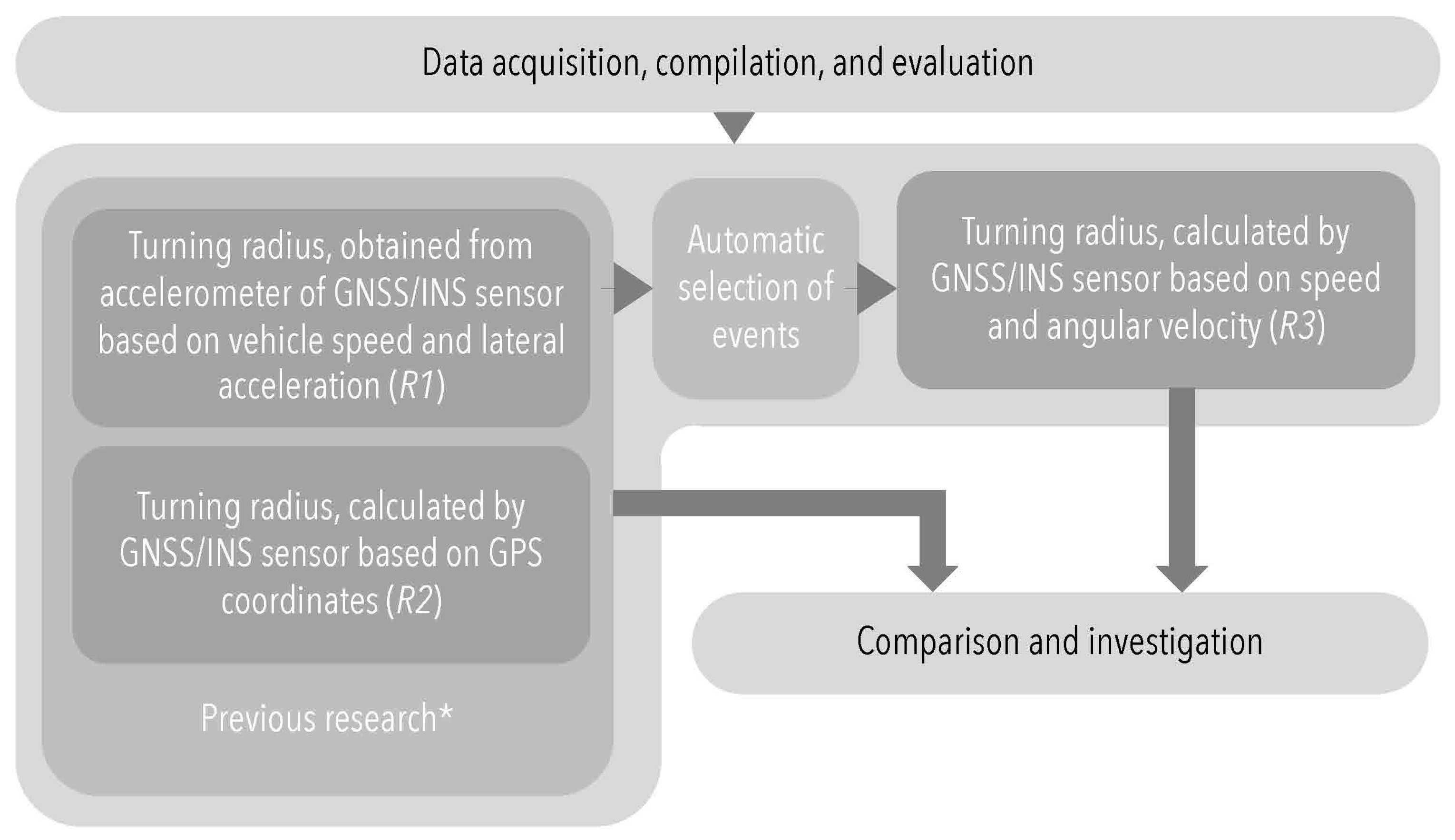
3.1. Data Evaluation

The calculation of the turning radii R1 and R2 is described in previous research [1]. The GNSS/INS speed data v and gyroscope data g z from IMU are indispensable in stipulating turning radius R3. The original formula based on [33] was customized for the purpose of the research, as in Equation (1):
R 3 = v | g z 1000 |   [ m ]
where v is the vehicle speed and g z 1000 is the average angular velocity during 1000 ms.
The parameter of g z 1000 is calculated as an absolute value, because angular velocity assigns positive values (in the right curves) and negative values (in the left curves). The obtained value for radius R3 is then averaged for selected events and roundabout quadrants.
As mentioned in previous research [1], Equation (1) does not consider the inclination of the road (positive or negative) or the vehicle due to inertia forces. This influence is considered in Section 4 in a statistical assessment of the results based on actual field tests. The road inclination was difficult to measure with the tests performed, where total inclination (roll) was measured, and inclination of vehicle and road were almost indistinguishable.
The previous research [1] showed the difference between R 1 and R 2 , and current research shows that R 3 is equal to R 2 for small roundabouts, so we can say that the inclination has a less significant impact on R 3 than on R 1 .

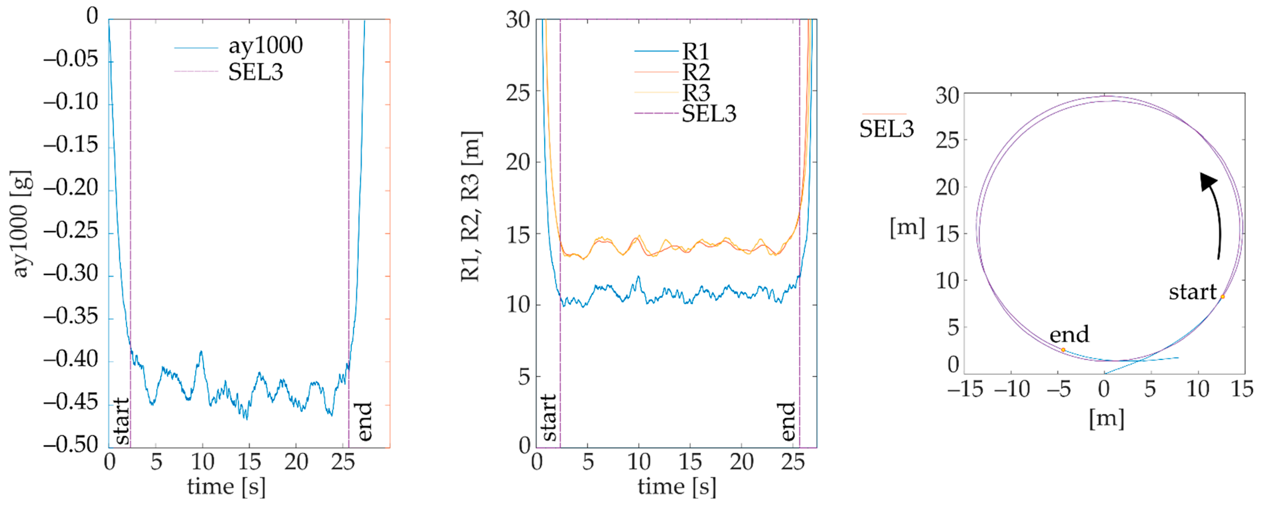
3.2. Automatic Selection of Events Based on Coefficient of Variation of a y 1000 (SEL3)

The automatic selection of events based on steady lateral accelerations a y 1000 (SEL1) and on MSE of R 1 and R 2 (SEL2) was explained in previous research [1].
The selection’s SEL3 goal is to specify the events owing to the calculation of the coefficient of variation C V of a y 1000 within a time window of 1 s, as follows:
C V = σ | μ |
where σ represents the moving standard deviation of a y 1000 within a time window of 1 s, and μ represents the moving mean of a y 1000 within a time window of 1 s.
The aim of this selection is to assign the event of main lateral acceleration acting in a roundabout (an example is given in Figure 2). For this purpose, the boundaries of the SEL3 event are represented by the first value (denoted as ‘start’ in Figure 2) and last value (denoted as ‘end’ in Figure 2), smaller than or equal to the value of CV of 0.04. This value is suitable for the selection of main lateral accelerations in small roundabouts for a given sensor.

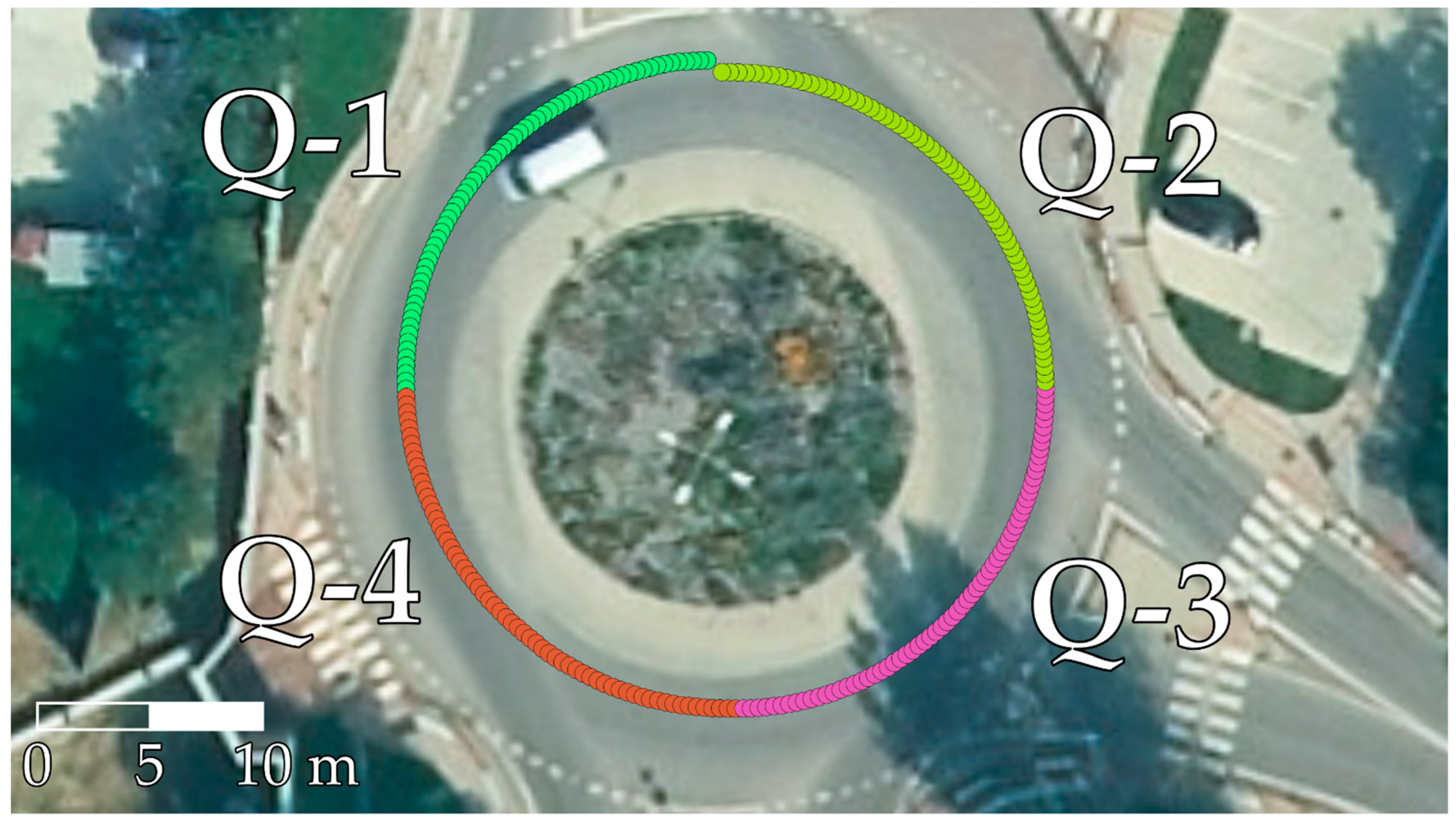
3.3. Automatic Identification of Roundabout Quadrants Based on Yaw

To study the different quadrants of a roundabout, the data from SEL3 turns were divided into quadrants based on the yaw data of the sensor. An example of this division is shown in Figure 3. This allowed the study of different quadrants of roundabouts in more detail, and also the comparison of vehicles and individual rides in individual roundabout quadrants. Only full quadrant data within the range of a 0.2–0.25 turn were evaluated from SEL3 turns.
The following test scenarios and vehicles were investigated in the field tests. Examples of vehicles are given in Figure 4.
Two pallet units with a mass of 1 ton and a low center of gravity were loaded into the van vehicles (denoted in Table 1 as V10 and V12). Vehicle combination V8 was tested with a 400 kg single-axle trailer, and vehicle combination V9 was tested with a 700 kg single-axle trailer. The position of the sensor and selected parameters of vehicles are indicated in Figure 5 and Table 1.
The sensor position was allocated to the vehicle’s longitudinal axis; specifically, on the roof of a passenger vehicle and directly under the roof of a van, with the antennas fitted on the roof. A lower sensor position corresponded to lower lateral acceleration values.

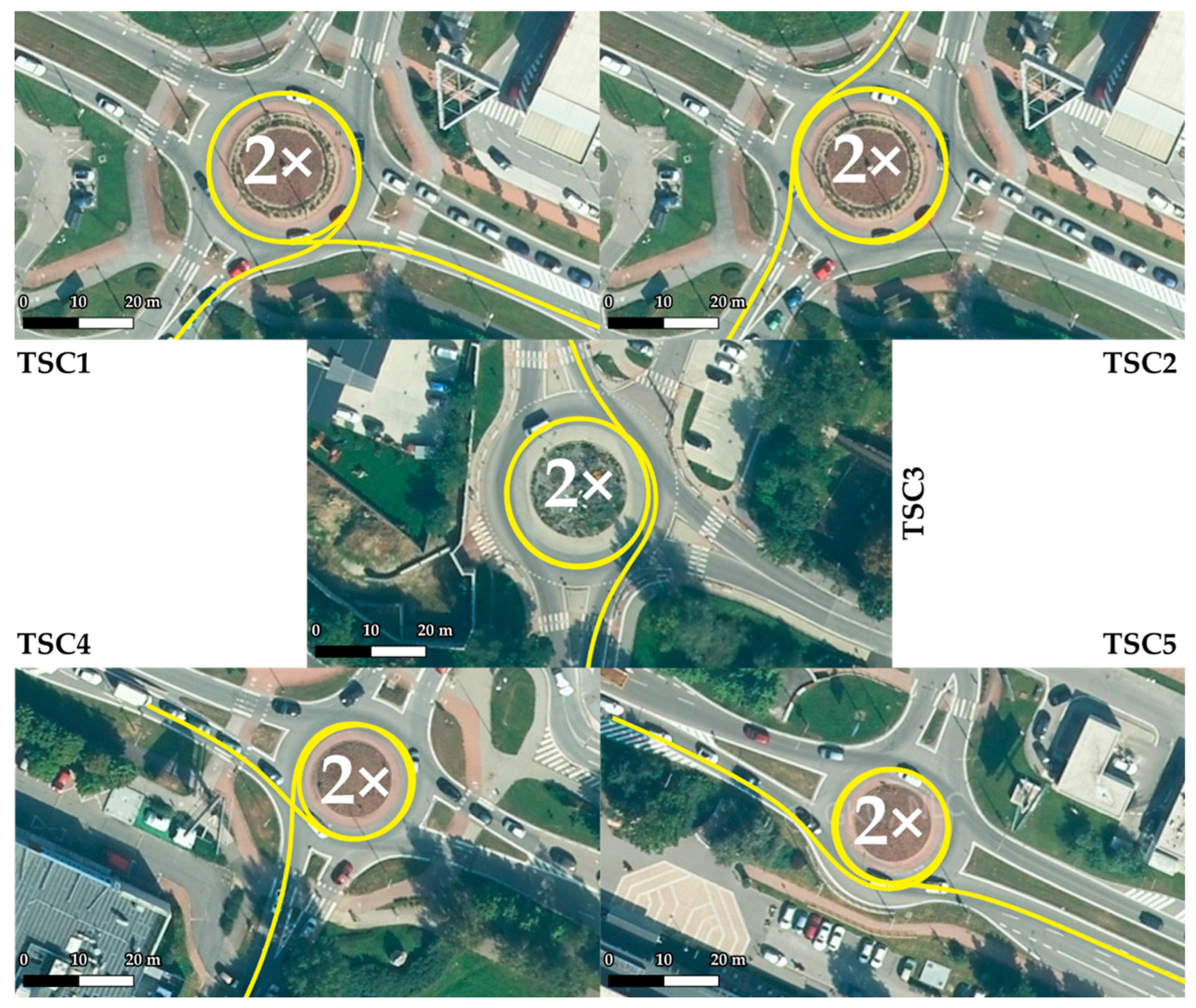
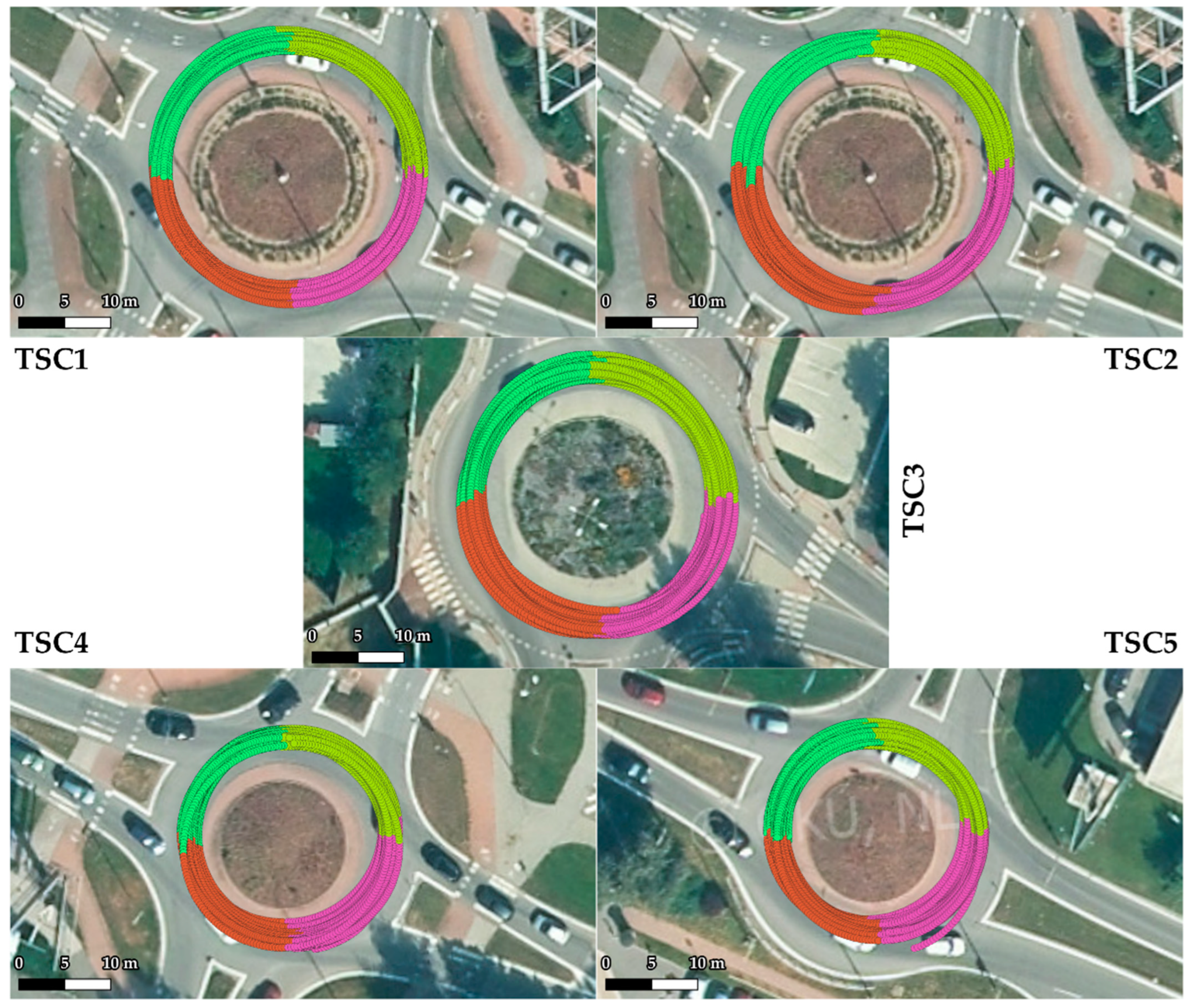
3.4. Roundabout Testing Scenarios

Five roundabout testing scenarios (further denoted as TSC) were deployed on 4 roundabouts in the tests. TSC1 and TSC2 were accomplished on the same roundabout. TSCs and the selected parameters of TSCs are given in Figure 6 and in Table 2. Each vehicle passed through each TSC 4 times.
The tests were carried out over 8 nights between 10:00 p.m. and 4:00 a.m. in order to avoid traffic as much as possible.
TSC1 was conducted on the largest roundabout in the study, with a minimum radius of 10.22 m and a maximum radius of 17.85 m. The roundabout was entered from the southwest direction and exited at exit 9 in the southeast direction. TSC2 was conducted on the same roundabout as TSC1. The roundabout was entered from the northeast direction and exited in the southeast direction via exit 10.
TSC3 took place on a roundabout with a minimum radius of 9.11 m and a maximum radius of 17.71 m. Dimensionally, this was a similar roundabout to that used in TSC1 and TSC2. The roundabout was entered from the east. It was then exited to the north via exit 11.
TSC4 measurements were taken at a roundabout with a minimum radius of 7.37 m and a maximum radius of 14.91 m. The roundabout was entered from the northwest and exited at exit 9 to the southeast. In terms of the crossing trajectory, TSC4 had a very similar crossing trajectory to TSC1, as confirmed by the same number of quadrants.
TSC5 was conducted on a roundabout with a minimum radius of 7.21 m and a maximum radius of 14.98 m. In terms of dimensions, TSC5 had similar dimensions to TSC4, being the smallest roundabout tested. The roundabout was entered from the northwest and exited at exit 10 to the southeast. TSC5 had a very similar crossing trajectory to TSC2, as indicated by the same number of quadrants. TSC3 also had a similar trajectory, where a different number of quadrants occurred due to a different exit distribution.

3.5. Statistical Investigation of Data

Based on the data shown in Table 2 (especially the roundabout radius parameter), we assigned testing scenarios to 2 groups (clusters). The first group contained data gathered from TSC1 to TSC3, and the second comprised TSC4 and TSC5 data.
Firstly, we had to confirm our assumption that there was no statistical difference between the scenarios belonging to each cluster. As a verification method, we chose the Friedman test (a non-parametric method that tests differences between several classes or categories, working with continuous dependent variables) [34]. Although we performed test scenarios using many vehicles, they all traveled the same testing routes (TSC1 to TSC5). Therefore, data obtained from sensors were considered as dependent variables (speed and lateral acceleration). The Friedman test (significance level of 0.05) proved that there was no statistical difference between the gathered data within each group/cluster.
Secondly, we planned to analyze the impact of different vehicle types on data collected from sensors, as well on R1, R2, and R3 calculations. We set 2 assumptions, as follows:
  • A1: There is a statistical difference between vehicle types within each data cluster.
  • A2: If we test individual roundabout quadrants instead of the entire roundabout, we will obtain different results compared to A1.
Both hypotheses were verified by the Friedman test. Since this test allows analysis of mean ranks for input variables, post hoc analysis allowed us to identify vehicles with the highest/lowest values of certain driving dynamics. Due to this analysis, we were also able to ascertain whether the calculation of all 3 turning radii were independent of individual driving styles. The results delivered by the Friedman test indicated that driving dynamics had an impact on the sensor variables of speed and lateral acceleration (confirming A1). We identified significant statistical differences in the collected sensor data related to V6 and V7 (V6 gained the highest values of speed and lateral acceleration, while V7 reached the lowest values; see Table 1). For both data clusters, V1 and V11 oscillated close to the upper decision limit (relatively high speed and acceleration compared to the other vehicle types).
A2 testing indicated similar (although not identical) results. Results obtained in the cases of vehicles V6 and V7 were identified as significantly different compared to the other vehicles, and in the cases of vehicles V1 and V11 were often close to the upper limit. However, we also recognized one novel case worth underlining. In the first testing group (TSC1–TSC3), only in quadrants 1 and 2 were results in the case of vehicle V8 close to the lower decision limit. This indicates that after V8 entered the roundabout, it passed the first 2 parts of the roundabout with a lower speed than other vehicles. This information reflects our assumption that the driver’s experience could partially impact the results, but the more important factor was the vehicle type used. Thus, we can state that in general, there was no difference between the results obtained from A1 and A2, respectively. An overview of the collected data can be found in Table 3 and Table 4.
On the other hand, according to the measured data, higher speed implied higher lateral acceleration. We did not find any evidence regarding the impact of driving dynamics on R1–R3 calculation, which means that the R3 Formula (1) can be used in real applications.
To compare measured and calculated parameters, we needed to evaluate the quality of created regression models. We chose the following metrics:
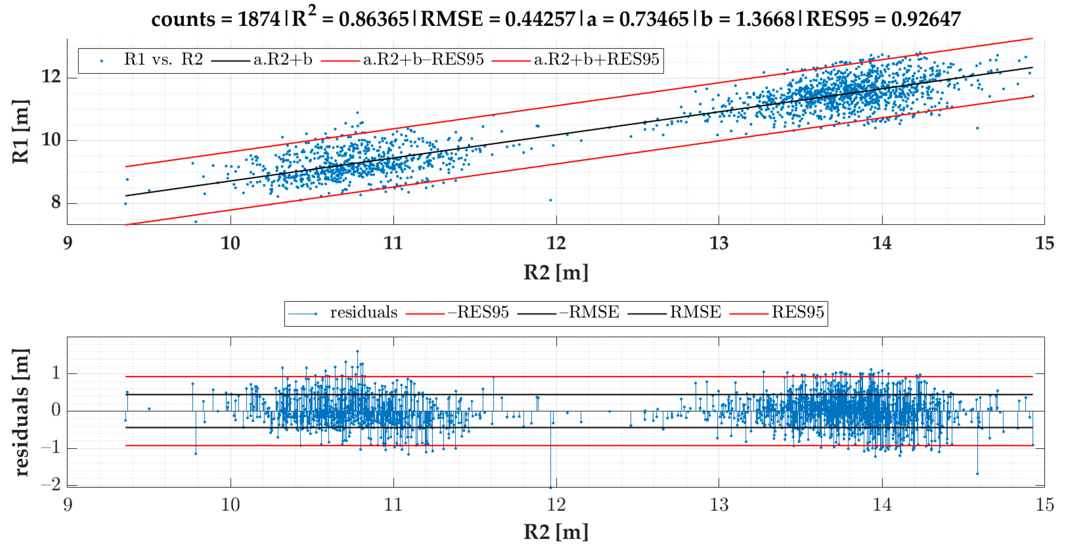
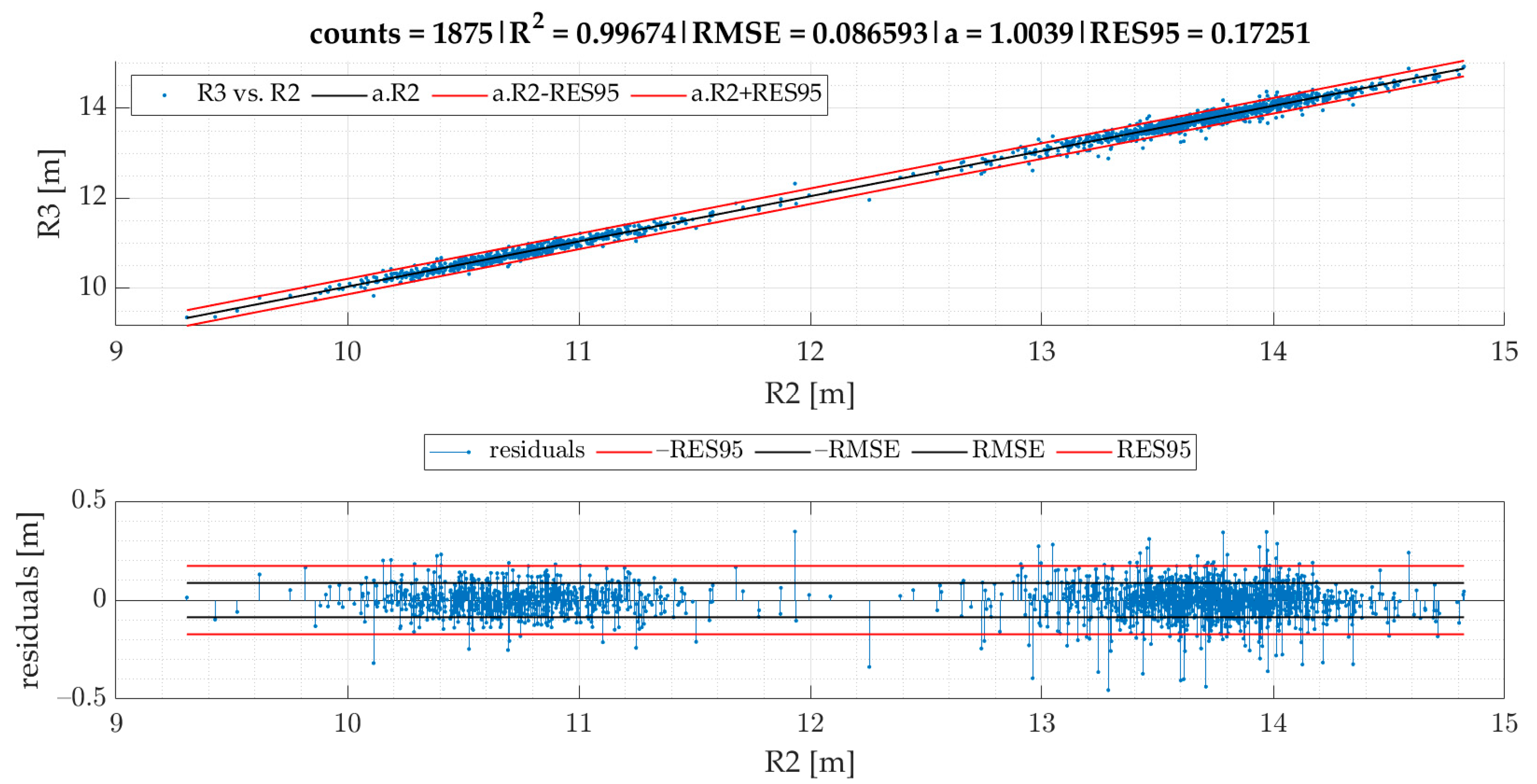
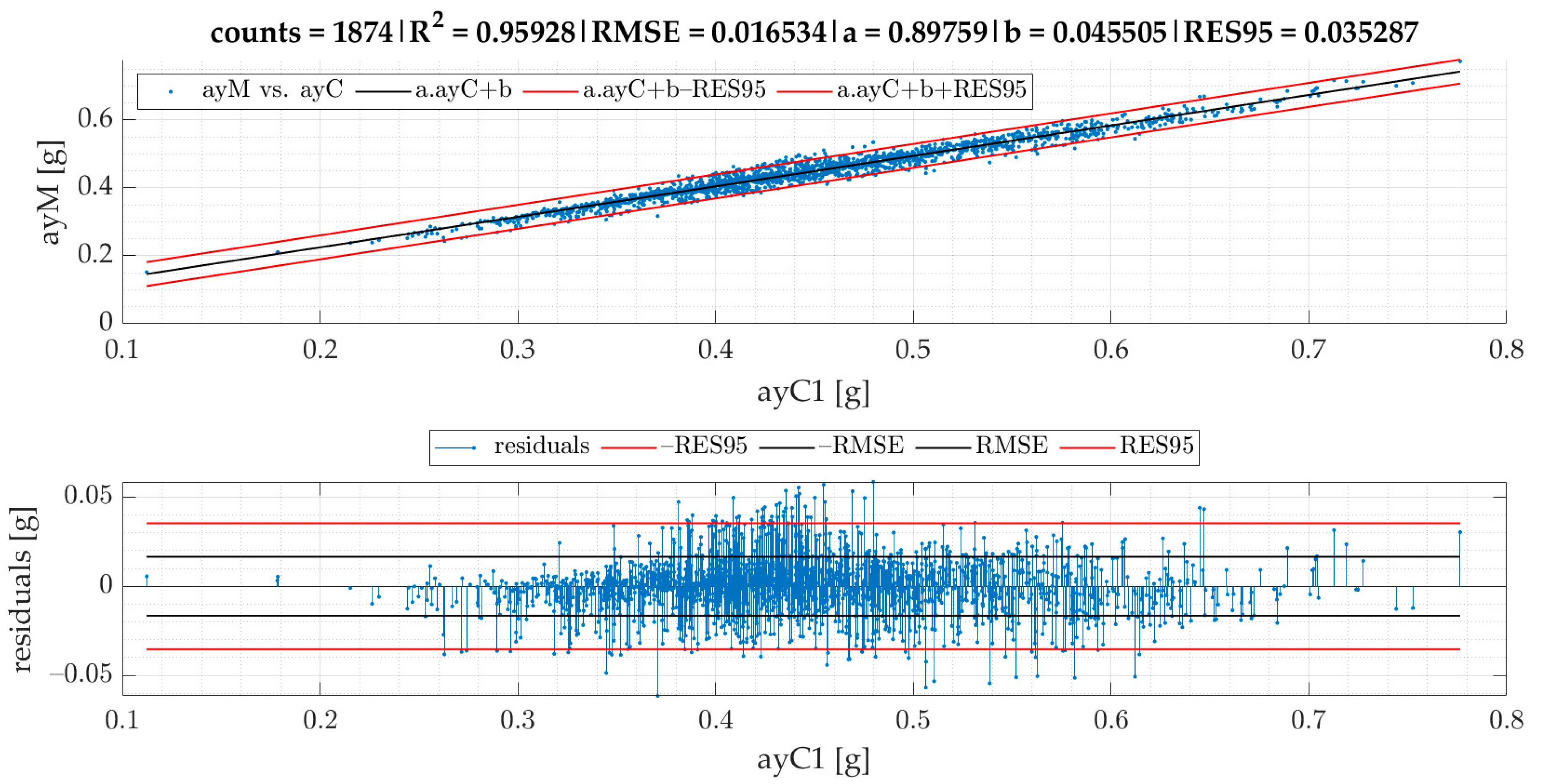
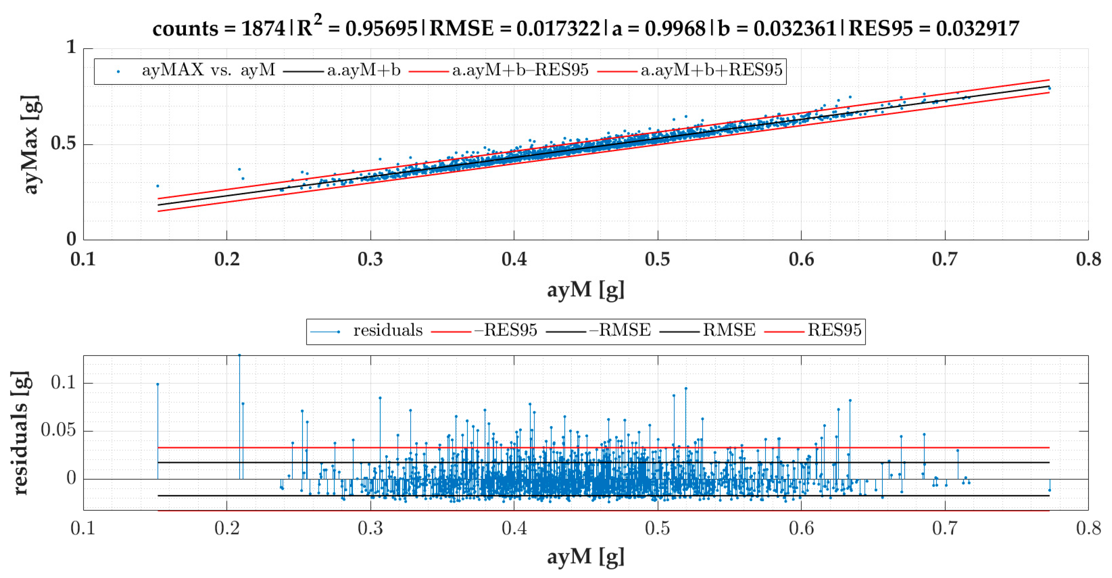
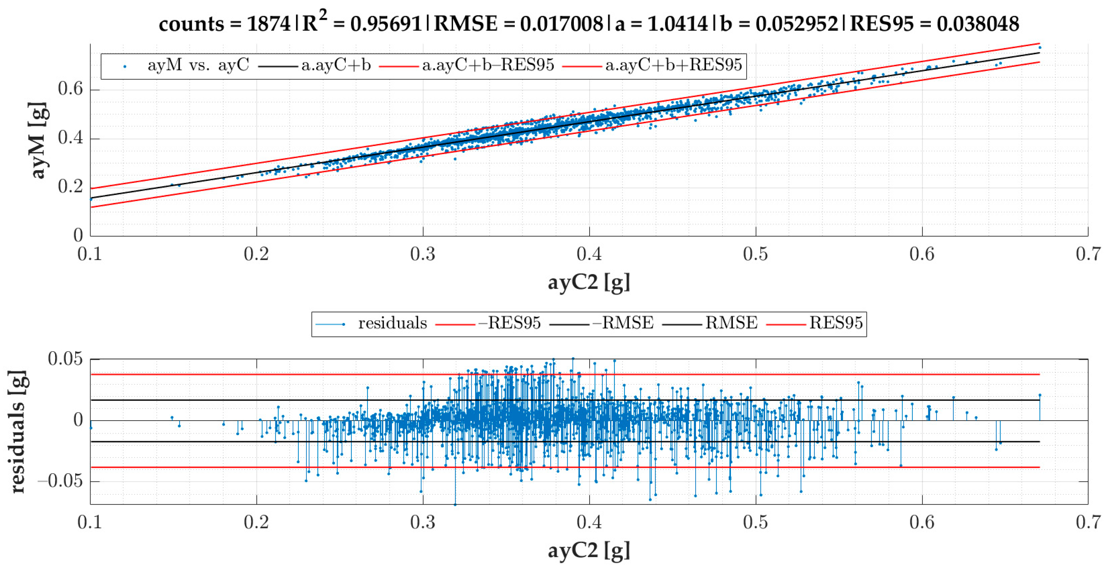
  • Mean squared error (MSE): measures the quality of the prediction model based on Euclidean distance. The square root of MSE (RMSE) has the same units as an estimated variable [35].
  • R2: the coefficient of determination. It measures the goodness of fit of a prediction model.
  • RES95: corresponds to the 95th percentile of the absolute value of residuals (errors).

4. Results

In the current section, Figure 7 gives the results of SEL3 divided into quadrants for all the TSCs. We provide equations for turning radii and lateral acceleration based on statistical evaluation of the data (Figure 8, Figure 9, Figure 10, Figure 11 and Figure 12).
The linear regression models designated for turning radii R1 and R2 are presented in Figure 8; those for turning radii R3 and R2 are presented in Figure 9; those for measured lateral acceleration a y M vs. calculated average lateral acceleration a y C 1 are shown in Figure 10; those for a y M vs. a y C 2 are shown in Figure 11; and those for maximum lateral acceleration a y M a x   vs .   a y M are reported in Figure 12.
The linear coefficient multiplies the predictor values (x-axis), while coefficient b (also called bias or intercept) is the point where the function crosses the y-axis.
Residuals are calculated after running the regression model and are depicted on the graph located below the scatter plot. Residuals represent differences between the observed values and the estimated values (vertical lines). The residual plot allowed us to validate the model represented by the line of best fit. The good regression model is characterized by symmetric residual distribution, as well as a high density of points that are close to the origin and a low density of points that are away from the origin. As seen in Figure 8, Figure 9, Figure 10, Figure 11 and Figure 12, residuals crossed the red lines only in a few cases. Red lines (RES95) describe 95th percentiles for the residuals.
A detailed look at Figure 9 shows an example of a very strong relationship between the measured and predicted values. As both variables are expressed in the same range and the coefficient a is close to one, we could have removed the intercept, so that the regression model was significant.
The linear regression models from Figure 8, Figure 9, Figure 10, Figure 11 and Figure 12 give an equation expressed as follows:
R 1 c S E L 3 = 0.73465 · R 2 1.36679   [ m ]
a y C 1 = v 2 0.73465 · R 2 1.36679   [ g ]
R 3 c S E L 3 = 1.00394 · R 2   [ m ]
Equation (5) demonstrates that R 3 c S E L 3 is almost identical to R2. The RES95 value shows that 95% of all residuals are allocated below the absolute error of 0.17 m. Based on modification of Equation (1), Equation (6) for the calculation of a y C 2 can be expressed as:
a y C 2 = v · | g z 1000 | 9.81   [ g ]
Equation (6) is based on speed and angular velocity and is not influenced by the turning radii.
Based on the results presented in Figure 8 and Figure 10, the following formula for the calculation of a y M c 1 can be stipulated:
a y M c 1 = 0.89759 · v 2 0.73465 · R 2 1.36679   + 0.04551   [ g ]
Based on Equation (6) and the model given in Figure 11, the following formula for the calculation of a y M c 2 can be designated:
a y M c 2 = 1.04143 · v · | g z 1000 | 9.81 + 0.05295   [ g ]
Based on the results shown in Figure 8, Figure 10 and Figure 11, Equation (9) for the calculation of a y M a x c 1 was obtained:
a y M a x c 1 = 0.99680 · ( 0.89759 · v 2 0.73465 · R 2 1.36679   + 0.04551 ) + 0.03236   [ g ]
a y M a x c 1 = 0.89471 · v 2 0.73465 · R 2 1.36679 + 0.07772   [ g ]
Based on Equation (6) and the results given in Figure 11 and Figure 12, Equations (11) and (12) for the calculation of a y M a x c 2 were obtained:
a y M a x c 2 = 0.99680 · ( 1.04143 · v · | g z 1000 | 9.81 + 0.05295 ) + 0.03236   [ g ]
a y M a x c 2 = 1.03809 · v · | g z 1000 | 9.81 + 0.08514   [ g ]

5. Discussion

The aim of the tests was to measure the long-term accelerations for regular road traffic driving in predefined vehicles (categories of vehicles: M1, N1, and O1) on four small roundabouts with five TSCs.
Based on the gathered data, we created a methodology able to calculate turning radius and lateral acceleration in a simplified manner, by using widely available and relatively cheap sensors (GPS with gyroscope and accelerometer). Testing scenarios included the types of small-diameter roundabouts that dominate modern cities. As shown in Table 3 and Table 4, the average speed and lateral acceleration of tested vehicles for each testing scenario (TSC) were different. As the proposed methodology had to be applicable in actual situations, we tested the influence of different vehicle types and individual driving dynamics on turning radius computations. Statistical investigation proved that our approach eradicated these impacts. This knowledge was a significant support for the R3 vs. R2 comparison and indicated that R3 could be completely substituted by R2, which we believe is one of the main benefits of this article.
The differentiated accelerations could only be measured during multiple passages through roundabouts at different speeds. The SEL3 selection, based on the coefficient of variation of a y 1000 , was applied for the selection of events. The data from SEL3 were divided into quadrants based on yaw sensor data to enable study of the different quadrants of the roundabouts.
The average speed and lateral acceleration of SEL3 quadrants for individual vehicles and TSCs are given in Table 3, and those for individual quadrants in Table 4.

6. Conclusions

In this research, we identified dynamic events of lateral acceleration in small roundabouts for vehicles with a GVM of up to 3.5 t, because it is possible to achieve high lateral acceleration in small roundabouts. We aimed to study long lateral acceleration of vehicles passing through small roundabouts to compare the turning radii calculated by three different methods. We also divided the data measured on roundabout turns into four quadrants, which allowed the study of different quadrants of roundabouts in greater detail, and also enabled comparison of vehicles and individual rides in individual roundabout quadrants.
Based on the correlation models of turning radii, we developed a model for the calculation of turning radius, average lateral acceleration, and maximum lateral acceleration for small roundabouts. The models of turning radii were valid for small roundabouts within a range between 9 and 15 m for SEL3 selection of events and quadrant identification. The RMSE of the R 1 vs. the R 2 model was 0.44 m. We also proved that the turning radius R3 obtained from speed and angular velocity was equal to that of the turning radius R2 obtained from GPS coordinates in small roundabouts, which confirms two methods of turning radii calculation with almost identical results. The RMSE of the a y M vs. the a y C 1 model was 0.0165 g, while for a y M vs. a y C 2 , it was 0.0170 g, which indicates that a y C 1 calculation gives slightly better results than a y C 2 . The models are more precise in comparison to previous research. The data for the model of calculation of turning radius ought to be periodically collected and analyzed, as we plan to develop a tool allowing feedback for the employees responsible for fleet management. However, this concept will be a matter of future research alongside other research agendas mentioned below.
Navigation devices are accessible to almost everyone, whether on a smartphone, built into a vehicle’s infotainment system, or as an external device. Truck drivers use them frequently, but they are also often used by car drivers to monitor traffic situations. The algorithm proposed for calculating accelerations could be incorporated into navigation applications. Every smartphone is equipped with sensors, including an accelerometer, a gyroscope, and a GPS sensor. Our algorithm ensures the possibility of determining the radius of each roundabout by collecting anonymous navigation data. Following data collection, the speed that should not be exceeded when crossing the roundabout would be calculated based on the collected data and on our model. The driver would be warned to slow the vehicle down in order to avoid skidding or overturning. This feature would be particularly useful in poor road conditions and would also help drivers with loads with a high center of gravity.
The main purpose of this paper was to produce results for application in freight-securing recommendations, in ensuring the stability of transported load units, and in calculating expected lateral accelerations through small roundabouts for a given speed and turning radius. The obtained results were found to be promising; therefore, in future research, new tests will be performed involving U-turns as well as on larger roundabouts, simulating scenarios involving cargo-securing decisions and the transport stability of load units. The results can be applied to improve road safety. When further research is considered, the development of a tool allowing feedback for the employees responsible for fleet management can become a significant future research agenda, both in the case of road safety and transport economics. Additionally, the influence on transport economics is related to the abovementioned fact of smartphones equipped with appropriate components (listed in the previous paragraph), and technologies which can support a driver during a ride. Our results can also be applied to algorithms used for autonomous road vehicles.

Author Contributions

Conceptualization, J.J.; editing of the manuscript, J.J.; realization, J.J. and O.K.; introduction, J.J. and M.K.; literature review, M.K.; materials and methods, J.J., O.K., M.K. and J.G.; data curation, J.J., J.F. and O.K.; results, J.J. and J.G.; writing—original draft, J.J., J.F., O.K., J.G. and M.K.; visualization, J.J., O.K. and M.K.; final revision, J.J., J.F., M.K. and J.G. All authors have read and agreed to the published version of the manuscript.

Funding

This research was realized with the support of Operational Program Integrated Infrastructure 2014–2020 of the project: Innovative Solutions for Propulsion, Power and Safety Components of Transport Vehicles, code ITMS 313011V334, co-financed by the European Regional Development Fund.

Institutional Review Board Statement

Not applicable.

Informed Consent Statement

Not applicable.

Conflicts of Interest

The authors declare no conflict of interest.

References

  1. Jagelčák, J.; Gnap, J.; Kuba, O.; Frnda, J.; Kostrzewski, M. Determination of Turning Radius and Lateral Acceleration of Vehicle by GNSS/INS Sensor. Sensors 2022, 22, 2298. [Google Scholar] [CrossRef] [PubMed]
  2. Šurdonja, S.; Dragčević, V.; Deluka-Tiblja, A. Analyses of maximum-speed path definition at single-lane roundabouts. J. Traffic Transp. Eng. 2018, 5, 83–95. [Google Scholar] [CrossRef]
  3. Elvik, R. Effects on road safety of converting intersections to roundabouts: A review of evidence from non U.S. studies. Transp. Res. Rec. 2003, 1847, 1–10. [Google Scholar] [CrossRef]
  4. Jensen, S.U. Safety effects of converting intersections to roundabouts. Transp. Res. Rec. 2013, 2389, 22–29. [Google Scholar] [CrossRef] [Green Version]
  5. Retting, R.A.; Persaud, B.N.; Garder, P.; Lord, D. Crash and injury reduction following installation of roundabouts in the United States. Am. J. Public Health 2001, 91, 628–631. [Google Scholar] [CrossRef] [PubMed] [Green Version]
  6. Kennedy, J.V.; Peirce, J.; Summergrill, I. International comparison of roundabout design guidelines. In Proceedings of the 3rd International Symposium on Highway Geometric Design, Chicago, IL, USA, 29 June–1 July 2005; Transportation Research Board: Washington, DC, USA. [Google Scholar]
  7. Sun, Q.C.; Xia, J.C.; Foster, J.; Falkmer, T.; Lee, H. Pursuing Precise Vehicle Movement Trajectory in Urban Residential Area Using Multi-GNSS RTK Tracking. Transp. Res. Procedia 2017, 25, 2356–2372. [Google Scholar] [CrossRef]
  8. Pilko, H.; Brčić, D.; Šubić, N. Study of vehicle speed design of roundabouts. Građevinar 2014, 66, 407–416. [Google Scholar] [CrossRef] [Green Version]
  9. García Cuenca, L.; Guindel, C.; Aliane, N.; Armingol, J.M.; Fernández Andrés, J. Dataset Construction from Naturalistic Driving in Roundabouts. Sensors 2020, 20, 7151. [Google Scholar] [CrossRef]
  10. El Fatimi, A.; Addaim, A.; Guennoun, Z. A low-cost IMU/GPS position accuracy experimental study using extended kalman filter data fusion in real environments. E3S Web Conf. 2021, 297, 01040. [Google Scholar] [CrossRef]
  11. Quddus, M.A.; Noland, R.B.; Ochieng, W.Y. A High Accuracy Fuzzy Logic Based Map Matching Algorithm for Road Transport. J. Intell. Transp. Syst. 2006, 10, 103–115. [Google Scholar] [CrossRef] [Green Version]
  12. Małecki, K.; Wątróbski, J. Cellular Automaton to Study the Impact of Changes in Traffic Rules in a Roundabout: A Preliminary Approach. Appl. Sci. 2017, 7, 742. [Google Scholar] [CrossRef] [Green Version]
  13. Kalašová, A.; Skřivánek Kubíková, S.; Čulík, K.; Palúch, J. Comparison of traffic flow characteristics of signal controlled intersection and turbo roundabout. Arch. Automot. Eng. Arch. Motoryz. 2020, 88, 19–36. [Google Scholar]
  14. Bassani, M.; Mussone, L. Experimental analysis of operational data for roundabouts through advanced image processing. J. Traffic Transp. Eng. 2020, 7, 482–497. [Google Scholar] [CrossRef]
  15. Vlkovský, M.; Neubauer, J.; Malíšek, J.; Michálek, J. Improvement of Road Safety through Appropriate Cargo Securing Using Outliers. Sustainability 2021, 13, 2688. [Google Scholar] [CrossRef]
  16. Deveaux, D.; Higuchi, T.; Uçar, S.; Wang, C.-H.; Härri, J.; Altintas, O. Extraction of Risk Knowledge from Time To Collision Variation in Roundabouts. In Proceedings of the 2021 IEEE International Intelligent Transportation Systems Conference (ITSC), Indianapolis, IN, USA, 19–22 September 2021; pp. 3665–3672. [Google Scholar] [CrossRef]
  17. García Cuenca, L.; Sanchez-Soriano, J.; Puertas, E.; Fernandez Andrés, J.; Aliane, N. Machine Learning Techniques for Undertaking Roundabouts in Autonomous Driving. Sensors 2019, 19, 2386. [Google Scholar] [CrossRef] [Green Version]
  18. Capasso, A.; Bacchiani, G.; Molinari, D. Intelligent Roundabout Insertion using Deep Reinforcement Learning. In Proceedings of the 12th International Conference on Agents and Artificial Intelligence ICAART, Valletta, Malta, 22–24 February 2020; Volume 2, pp. 378–385. [Google Scholar] [CrossRef]
  19. Wang, W.; Jiang, L.; Lin, S.l.; Fang, H.; Meng, Q. Imitation learning based decision-making for autonomous vehicle control at traffic roundabouts. Multimed. Tools. Appl. 2022, 1–17. [Google Scholar] [CrossRef]
  20. Ali, M.A.H.; Mailah, M.; Jabbar, W.A.; Moiduddin, K.; Ameen, W.; Alkhalefah, H. Autonomous Road Roundabout Detection and Navigation System for Smart Vehicles and Cities Using Laser Simulator–Fuzzy Logic Algorithms and Sensor Fusion. Sensors 2020, 20, 3694. [Google Scholar] [CrossRef]
  21. Deluka Tibljaš, A.; Giuffrè, T.; Surdonja, S.; Trubia, S. Introduction of Autonomous Vehicles: Roundabouts Design and Safety Performance Evaluation. Sustainability 2018, 10, 1060. [Google Scholar] [CrossRef] [Green Version]
  22. Muhammad, N.; Åstrand, B. Intention Estimation Using Set of Reference Trajectories as Behaviour Model. Sensors 2018, 18, 4423. [Google Scholar] [CrossRef] [Green Version]
  23. Meng, X.; Wang, H.; Liu, B. A Robust Vehicle Localization Approach Based on GNSS/IMU/DMI/LiDAR Sensor Fusion for Autonomous Vehicles. Sensors 2017, 17, 2140. [Google Scholar] [CrossRef]
  24. Pauca, O.; Maxim, A.; Caruntu, C.-F. Multivariable Optimisation for Waiting-Time Minimisation at Roundabout Intersections in a Cyber-Physical Framework. Sensors 2021, 21, 3968. [Google Scholar] [CrossRef] [PubMed]
  25. Mischinger, M.; Rudigier, M.; Wimmer, P.; Kerschbaumer, A. Towards comfort-optimal trajectory planning and control. Veh. Syst. Dyn. 2018, 57, 1108–1125. [Google Scholar] [CrossRef]
  26. Pratelli, A.; Lupi, M.; Pratelli, C.; Farina, A. Mini-roundabouts for Improving Urban Accessibility. In Modelling of the Interaction of the Different Vehicles and Various Transport Modes; Sładkowski, A., Ed.; Lecture Notes in Intelligent Transportation and Infrastructure; Springer: Cham, Switzerland, 2020; pp. 333–382. [Google Scholar] [CrossRef]
  27. EN 12195-1:2010 Load Restraining on Road Vehicles. Safety. Part 1: Calculation of Securing Forces. Available online: https://standards.iteh.ai/catalog/standards/cen/72067d57-b90c-4ca5-8bd0-f876e25e6a6e/en-12195-1-2010 (accessed on 7 February 2022).
  28. IMO/ILO/UNECE Code of Practice for Packing of Cargo Transport Units (CTU Code). 2014. Available online: https://unece.org/fileadmin/DAM/trans/doc/2014/wp24/CTU_Code_January_2014.pdf (accessed on 7 February 2022).
  29. VDI 2700 Blatt 16 Ladungssicherung auf Straßenfahrzeugen—Ladungssicherung bei Transportern bis 7.5 t zGM. Available online: https://www.vdi.de/richtlinien/details/vdi-2700-blatt-16-ladungssicherung-auf-strassenfahrzeugen-ladungssicherung-bei-transportern-bis-75-t-zgm (accessed on 7 February 2022).
  30. Regulation (EU) 2018/858 of the European parliament and of the council of 30 May 2018 on the Approval and Market Sur-veillance of Motor Vehicles and Their Trailers, and of Systems, Components and Separate Technical Units Intended for Such Vehicles, Amending Regulations (EC) No 715/2007 and (EC) No 595/2009 and Repealing Directive 2007/46/EC. Available online: https://eur-lex.europa.eu/legal-content/EN/TXT/?uri=CELEX:02018R0858-20210926 (accessed on 8 February 2022).
  31. EN 12642:2016 Securing of Road on Road Vehicles—Body Structure of Commercial Vehicles—Minimum Requirements. Available online: https://standards.iteh.ai/catalog/standards/cen/cfb5d8a8-67c0-46fc-8b51-be9163596d6c/en-12642-2016 (accessed on 7 February 2022).
  32. EN 17321:2020 Intermodal Loading Units and Commercial Vehicles—Transport Stability of Packages—Minimum Require-ments and Tests. Available online: https://standards.iteh.ai/catalog/standards/sist/545c1b9f-c7d0-4196-aec8-eb1cbe8f0f81/ksist-fpren-17321-2020 (accessed on 7 February 2022).
  33. Balkwill, J. Performance Vehicle Dynamics; Butterworth-Heinemann: Oxford, UK, 2018; ISBN 978-0-12-812693-6. [Google Scholar]
  34. Friedman, M. The Use of Ranks to Avoid the Assumption of Normality Implicit in the Analysis of Variance. J. Am. Stat. Assoc. 1937, 32, 675–701. [Google Scholar] [CrossRef]
  35. Sammut, C.; Webb, G.I. (Eds.) Mean Squared Error. In Encyclopedia of Machine Learning; Springer: Boston, MA, USA, 2011. [Google Scholar] [CrossRef]
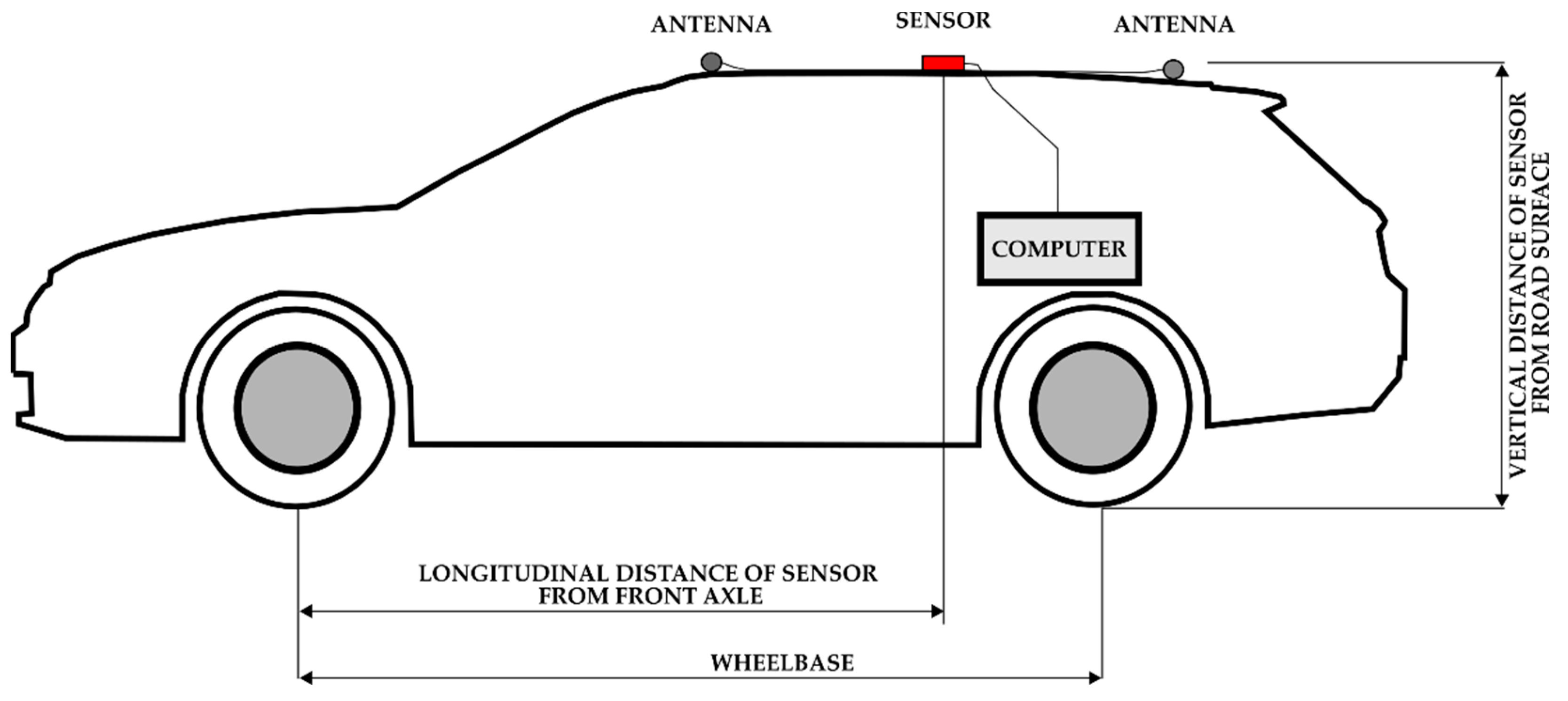
Figure 1. The research methodology (where * relates to [1]).
Sensors 22 04978 g001
Figure 2. Example measurement for automatic selection of event SEL3 based on CV of ay1000.
Sensors 22 04978 g002
Figure 3. Example selection of quadrants denoted as Q-1 to Q-4 based on yaw, visualized on an orthophoto map layer of GKÚ Bratislava, NLC.
Sensors 22 04978 g003
Figure 4. Vehicle combination V9 (in the left photo) and van vehicle V11 (in the right photo) applied in tests.
Sensors 22 04978 g004
Figure 5. Scheme of test-setup installation.
Sensors 22 04978 g005
Figure 6. Roundabout testing scenarios 1–5 visualized on an orthophoto map layer of GKÚ Bratislava, NLC.
Sensors 22 04978 g006
Figure 7. Results of SEL3 divided into quadrants Q-1 to Q-4 (colorized according to Figure 3) for roundabout TSC1–5, visualized on an orthophoto map layer of GKÚ Bratislava, NLC.
Sensors 22 04978 g007
Figure 8. R 1 vs. R 2 in the case of events for SEL3 quadrants.
Sensors 22 04978 g008
Figure 9. R 3 vs. R 2 in the case of events for SEL3 quadrants.
Sensors 22 04978 g009
Figure 10. Calculated a y C 1 vs. measured a y M of events for SEL3 quadrants.
Sensors 22 04978 g010
Figure 11. Calculated a y C 2 vs. measured of events for SEL3 quadrants.
Sensors 22 04978 g011
Figure 12. Maximum lateral acceleration a y M a x vs. average lateral acceleration a y M of events for SEL3 quadrants.
Sensors 22 04978 g012
Table 1. Selected parameters identifying the vehicles used in field tests.
IDVehicle NameManufacturing YearVehicle Category according to [30]Vehicle Mass
[kg]
Wheelbase
[mm]
Longitudinal Distance of Sensor from Front Axle
[mm]
Ratio of Position of the Sensor and Wheelbase
[mm]
Vertical Distance of Sensor from Road Surface
[mm]
V1VW Golf2001M11265250418050.721480
V2VW Polo2006M11138244116920.691480
V3VW Polo2004M11033246517210.71500
V4VW Touareg2003M1G2420286518700.651713
V5Opel Antara2014M11941271018150.671705
V6Škoda Fabia2014M11116246017800.721550
V7Honda Accord Combi2008M11766269018500.691445
V8VW Touareg; trailer2003; 2005M1G; O128502865; 281818700.651713
V9Mitsubishi Pajero; trailer1986; 1989M1G; O124802690;
3350
19010.711890
V10Renault Master2019N13350432530200.72320
V11Renault Master2019N12350432530200.72320
V12Renault Master2014N13330436029200.672355
V13Renault Master2014N12330436029200.672355
Table 2. Selected parameters of TSC.
TSCMinimum
Radius of Roundabout
[m]
Maximum Radius of Roundabout
[m]
Minimum
Radius R2 of Quadrant of SEL3
[m]
Maximum
Radius R2 of Quadrant of SEL3
[m]
Number of ExitsAverage Number of Turns from SEL3Number of Quadrants
110.2217.8512.6614.8041.786
210.2217.8512.9614.8241.947
39.1117.7111.8714.7942.018
47.3714.919.9812.0941.666
57.2114.9810.1112.2531.907
Table 3. Average speed v and lateral acceleration a y 1000 of SEL3 quadrants for individual vehicles and TSC.
TSC1TSC2TSC3TSC4TSC5Total AverageRank
vay1000vay1000vay1000vay1000vay1000vay1000vay1000
V126.50−0.48527.43−0.51026.28−0.47823.75−0.48525.73−0.55825.93−0.50333
V224.40−0.38225.67−0.42226.76−0.46124.53−0.48824.52−0.47525.16−0.44657
V323.96−0.40323.51−0.38923.86−0.39322.74−0.46120.73−0.37722.96−0.4031111
V423.42−0.39124.33−0.40926.23−0.48023.13−0.46924.74−0.53824.43−0.45965
V524.44−0.41324.70−0.41324.83−0.42523.78−0.47722.38−0.41924.09−0.42989
V627.33−0.50428.83−0.55428.45−0.54525.78−0.56426.81−0.60627.52−0.55511
V721.04−0.31221.66−0.33622.68−0.35421.39−0.39220.92−0.35921.59−0.3501313
V822.84−0.36923.75−0.39023.57−0.39721.76−0.41721.99−0.41722.83−0.3981212
V924.80−0.44524.68−0.44824.99−0.45722.54−0.46722.85−0.46824.01−0.45796
V1024.36−0.41925.60−0.45125.66−0.44922.10−0.43922.46−0.43524.12−0.43978
V1126.02−0.46827.19−0.49727.41−0.50024.58−0.52224.98−0.52226.09−0.50322
V1223.14−0.37424.04−0.40025.29−0.43722.23−0.42122.20−0.42023.45−0.4111010
V1324.73−0.41827.33−0.49928.41−0.53422.45−0.43524.41−0.48625.64−0.47944
Total average24.37−0.41425.25−0.43825.67−0.45323.19−0.46623.41−0.46624.44−0.448
Rank3524135241
Table 4. Average lateral acceleration a y 1000 of SEL3 quadrants for individual vehicles, TSCs, and quadrants.
V1V2V3V4V5V6V7V8V9V10V11V12V13Total AverageRank
TSC1−0.485−0.382−0.403−0.391−0.413−0.504−0.312−0.369−0.445−0.419−0.468−0.374−0.418−0.414
Q-1−0.465−0.364−0.388−0.392−0.398−0.494−0.304−0.374−0.441−0.412−0.459−0.382−0.422−0.4074
Q-2−0.474−0.380−0.389−0.392−0.409−0.511−0.313−0.355−0.444−0.413−0.456−0.364−0.401−0.4083
Q-3−0.518−0.427−0.437−0.412−0.447−0.554−0.324−0.384−0.452−0.447−0.507−0.378−0.419−0.4391
Q-4−0.513−0.376−0.430−0.374−0.416−0.458−0.312−0.371−0.452−0.416−0.470−0.375−0.444−0.4132
TSC2−0.510−0.422−0.389−0.409−0.413−0.554−0.336−0.390−0.448−0.451−0.497−0.400−0.499−0.438
Q-1−0.510−0.478−0.385−0.425−0.438−0.595−0.318−0.400−0.447−0.465−0.518−0.413−0.534−0.4551
Q-2−0.519−0.442−0.399−0.422−0.419−0.577−0.349−0.404−0.460−0.472−0.517−0.394−0.485−0.4492
Q-3−0.510−0.405−0.386−0.409−0.407−0.529−0.338−0.391−0.455−0.445−0.495−0.404−0.493−0.4343
Q-4−0.500−0.392−0.383−0.388−0.400−0.536−0.330−0.370−0.430−0.430−0.468−0.397−0.500−0.4244
TSC3−0.478−0.461−0.393−0.480−0.425−0.545−0.354−0.397−0.457−0.449−0.500−0.437−0.534−0.453
Q-1−0.459−0.421−0.385−0.471−0.405−0.534−0.360−0.386−0.448−0.432−0.483−0.432−0.518−0.4403
Q-2−0.465−0.427−0.366−0.435−0.410−0.510−0.353−0.366−0.435−0.431−0.467−0.424−0.508−0.4294
Q-3−0.492−0.496−0.395−0.494−0.443−0.575−0.340−0.412−0.450−0.444−0.509−0.432−0.535−0.4622
Q-4−0.496−0.494−0.426−0.514−0.444−0.560−0.363−0.421−0.491−0.485−0.539−0.456−0.573−0.4801
TSC4−0.485−0.488−0.461−0.469−0.477−0.564−0.392−0.417−0.467−0.439−0.522−0.421−0.435−0.466
Q-1−0.480−0.481−0.457−0.481−0.477−0.530−0.388−0.418−0.468−0.418−0.510−0.426−0.438−0.4623
Q-22−0.512−0.494−0.474−0.489−0.481−0.563−0.398−0.430−0.488−0.456−0.550−0.426−0.440−0.4782
Q-3−0.462−0.458−0.435−0.444−0.461−0.571−0.378−0.400−0.450−0.434−0.501−0.405−0.420−0.4494
Q-4−0.482−0.542−0.490−0.465−0.503−0.585−0.412−0.426−0.462−0.433−0.523−0.436−0.453−0.4801
TSC5−0.558−0.475−0.377−0.538−0.419−0.606−0.359−0.417−0.468−0.435−0.522−0.420−0.486−0.466
Q-1−0.551−0.467−0.352−0.528−0.399−0.596−0.326−0.397−0.452−0.412−0.509−0.394−0.461−0.4484
Q-2−0.573−0.476−0.361−0.538−0.415−0.583−0.376−0.429−0.470−0.445−0.529−0.440−0.502−0.4712
Q-3−0.543−0.465−0.403−0.525−0.420−0.623−0.380−0.417−0.478−0.441−0.510−0.413−0.477−0.4673
Q-4−0.573−0.512−0.406−0.585−0.465−0.638−0.351−0.435−0.478−0.446−0.549−0.443−0.526−0.4931
Total
average
−0.503−0.446−0.403−0.459−0.429−0.555−0.350−0.398−0.457−0.439−0.503−0.411−0.479−0.448
Publisher’s Note: MDPI stays neutral with regard to jurisdictional claims in published maps and institutional affiliations.

