
Influence of Analog and Digital Crease Lines on Mechanical Parameters of Corrugated Board and Packaging


Abstract
:1. Introduction
2. Materials and Methods
2.1. Corrugated Board Testing
2.1.1. Edge Crush Test
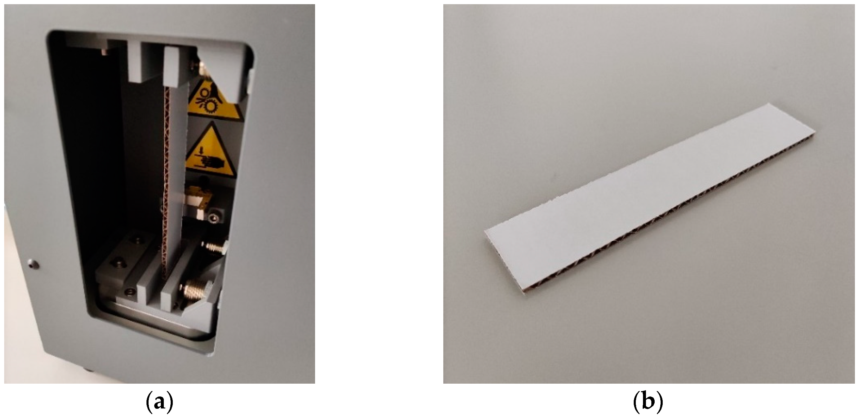
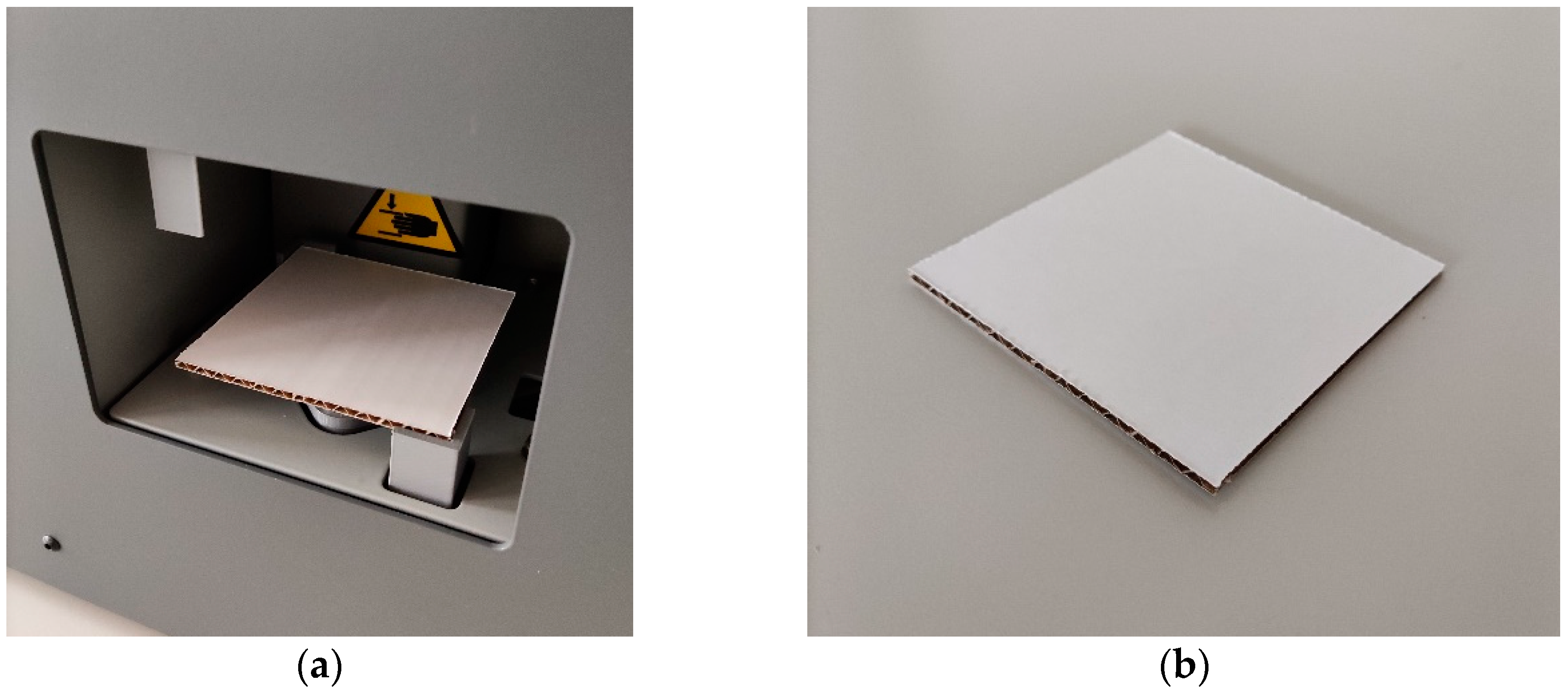
2.1.2. Shear Stiffness Test
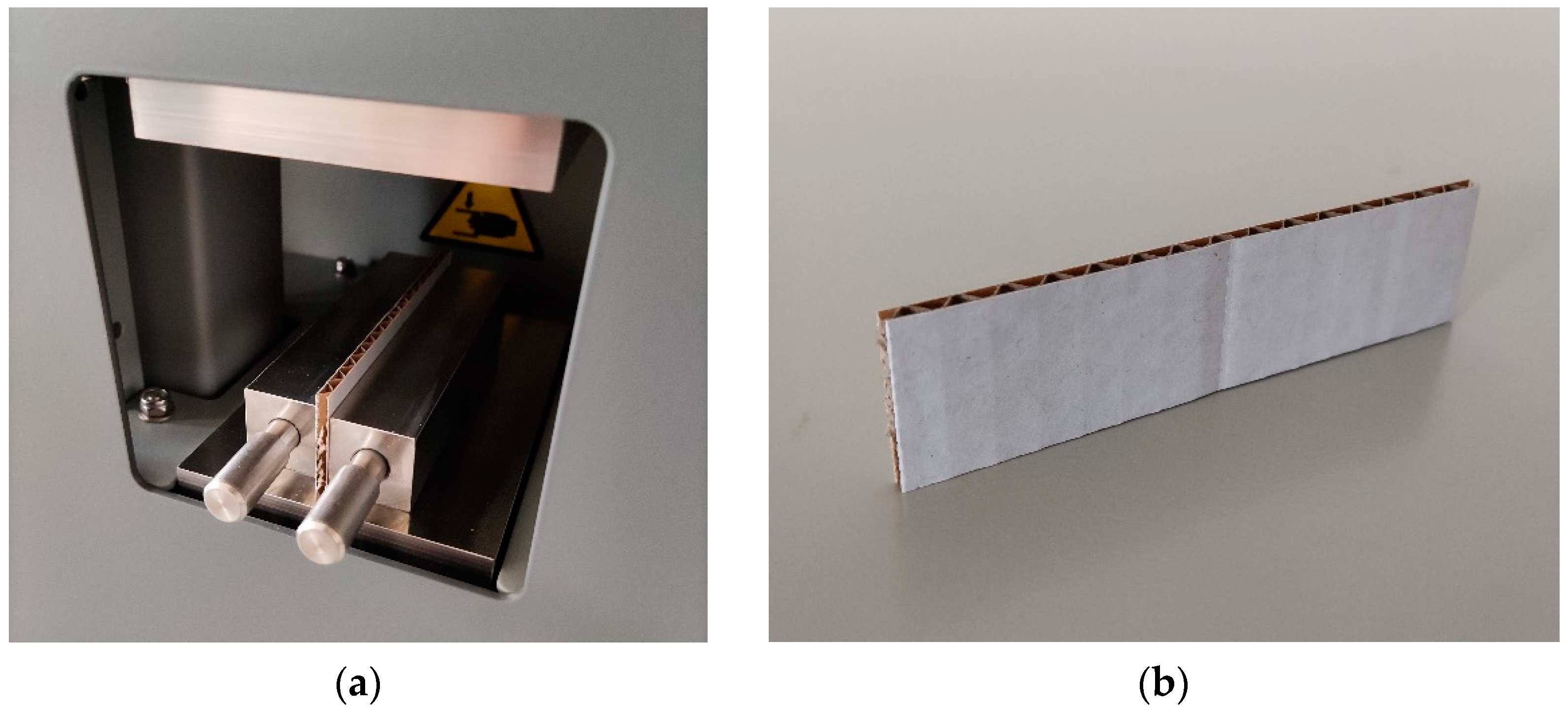
2.1.3. Torsion Stiffness Test
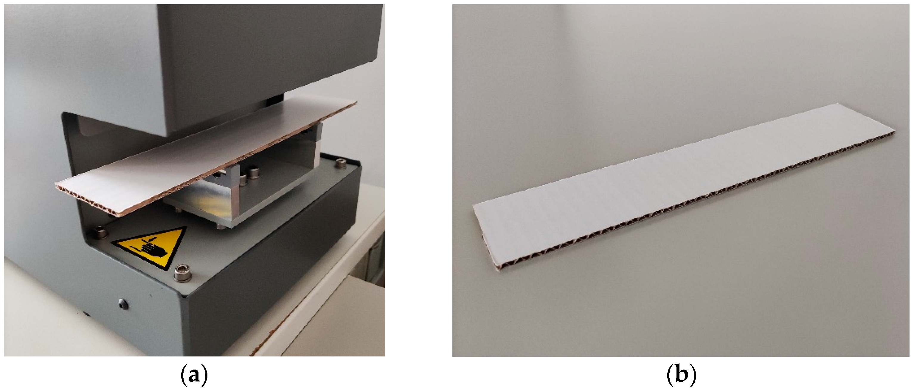
2.1.4. Bending Stiffness Test
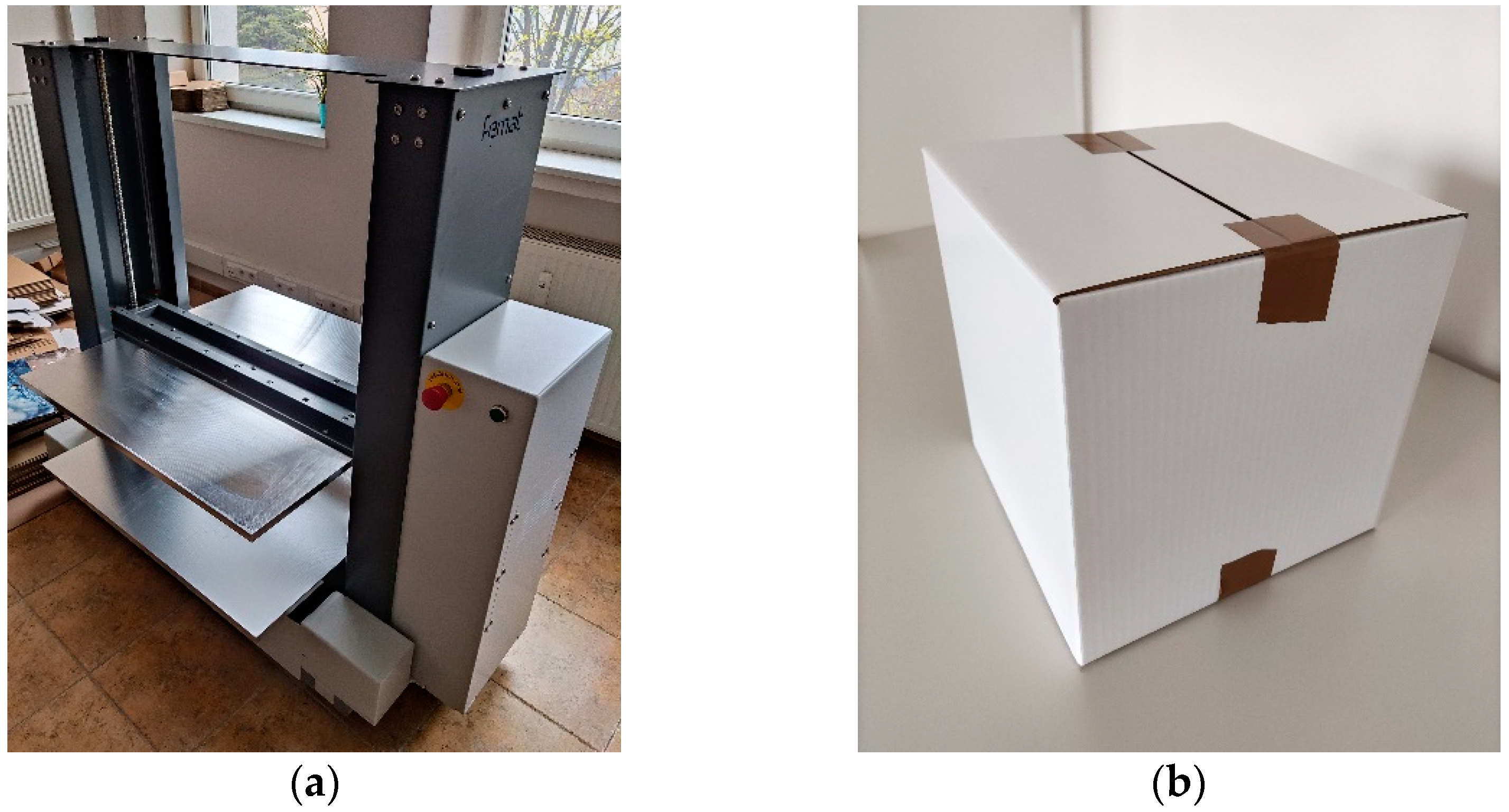
2.2. Compression Test of Corrugated Board Packaging
2.3. Analog and Digital Box Finishing Techniques
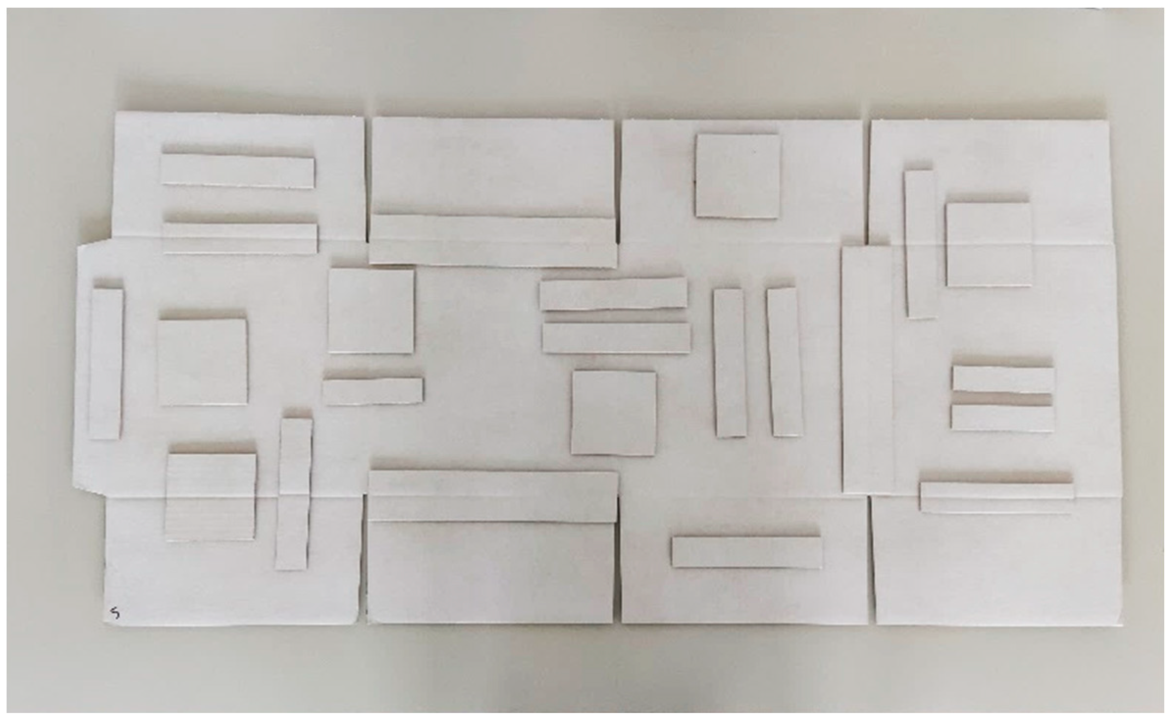
2.4. Corrugated Board and Box Samples
- ●
- testliner 130 g/;
- ●
- fluting 100 g/;
- ●
- testliner 130 g/.
- ●
- kraftliner brown 135 g/;
- ●
- fluting 100 g/;
- ●
- kraftliner brown 135 g/.
- ●
- kraftliner white coated 145 g/;
- ●
- fluting 100 g/;
- ●
- duplex white 135 g/
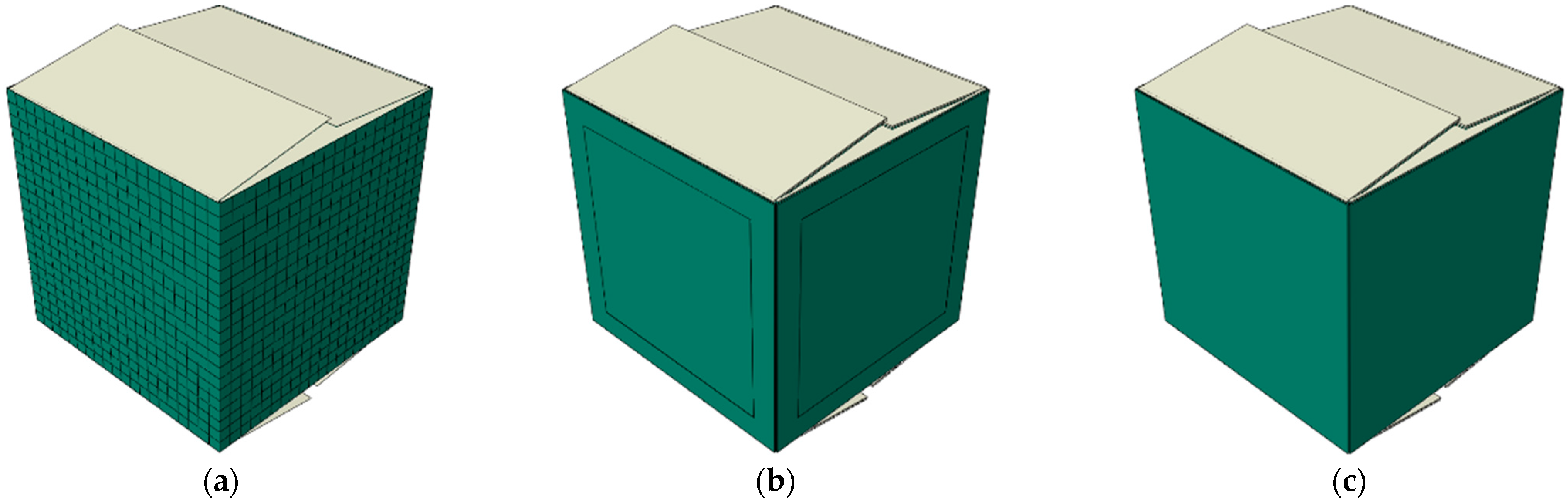
2.5. Numerical Model of a Box
3. Results
3.1. Corrugated Board Testing
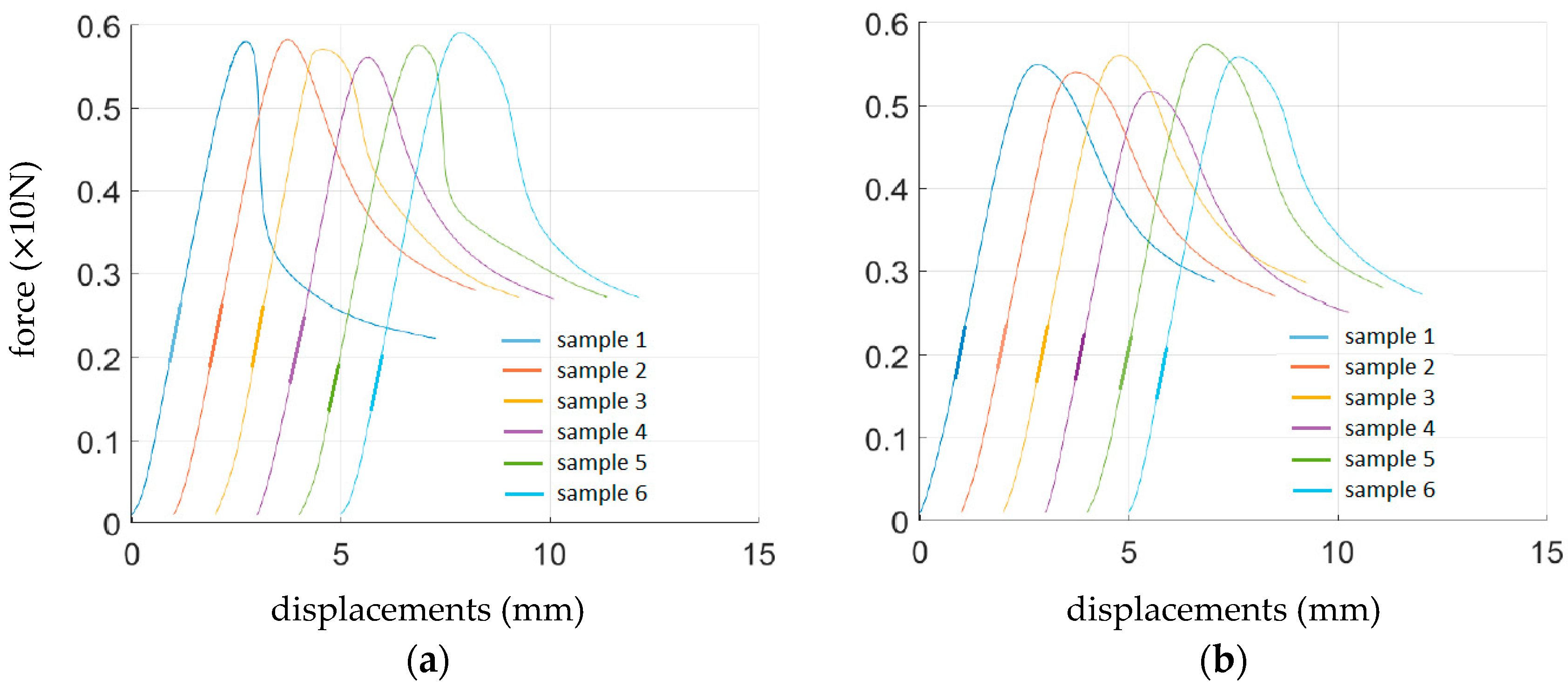
3.2. Compression Test of Corrugated Board Packaging
3.3. Numerical Validation
4. Discussion
5. Conclusions
Author Contributions
Funding
Institutional Review Board Statement
Informed Consent Statement
Data Availability Statement
Acknowledgments
Conflicts of Interest
References
- Palmeira, M.; Musso, F. 3Rs of sustainability values for retailing customers as factors of influence on consumer behavior. In Handbook of Research on Retailing Techniques for Optimal Consumer Engagement and Experiences, 1st ed.; Musso, F., Druica, E., Eds.; IGI Global: Hershey, PA, USA, 2020; pp. 421–444. [Google Scholar] [CrossRef]
- Urbanik, T.J.; Frank, B. Box compression analysis of world-wide data spanning 46 years. Wood Fiber Sci. 2006, 38, 399–416. [Google Scholar]
- Garbowski, T.; Gajewski, T.; Grabski, J.K. Estimation of the compressive strength of corrugated cardboard boxes with various openings. Energies 2021, 14, 155. [Google Scholar] [CrossRef]
- Garbowski, T.; Gajewski, T.; Grabski, J.K. Estimation of the compressive strength of corrugated cardboard boxes with various perforations. Energies 2021, 14, 1095. [Google Scholar] [CrossRef]
- Mrówczyński, D.; Garbowski, T.; Knitter-Piątkowska, A. Estimation of the compressive strength of corrugated board boxes with shifted creases on the flaps. Materials 2021, 14, 5181. [Google Scholar] [CrossRef] [PubMed]
- Frank, B. Corrugated box compression—A literature survey. Packag. Technol. Sci. 2014, 27, 105–128. [Google Scholar] [CrossRef]
- Garbowski, T.; Gajewski, T.; Mrówczyński, D.; Jędrzejczak, R. Crushing of Single-Walled Corrugated Board during Converting: Experimental and Numerical Study. Energies 2021, 14, 3203. [Google Scholar] [CrossRef]
- Garbowski, T.; Grabski, J.K.; Marek, A. Full-field measurements in the edge crush test of a corrugated board—Analytical and numerical predictive models. Materials 2021, 14, 2840. [Google Scholar] [CrossRef]
- Gajewski, T.; Garbowski, T.; Staszak, N.; Kuca, M. Crushing of Double-Walled Corrugated Board and Its Influence on the Load Capacity of Various Boxes. Energies 2021, 14, 4321. [Google Scholar] [CrossRef]
- Jamsari, M.A.; Kueh, C.; Gray-Stuart, E.M.; Dahm, K.; Bronlund, J.E. Modelling the impact of crushing on the strength performance of corrugated fibreboard. Packag. Technol. Sci. 2020, 33, 159–170. [Google Scholar] [CrossRef]
- Bai, J.; Wang, J.; Pan, L.; Lu, L.; Lu, G. Quasi-static axial crushing of single wall corrugated paperboard. Compos. Struct. 2019, 226, 111237. [Google Scholar] [CrossRef]
- Garbowski, T.; Gajewski, T.; Grabski, J.K. The role of buckling in the estimation of compressive strength of corrugated cardboard boxes. Materials 2020, 13, 4578. [Google Scholar] [CrossRef] [PubMed]
- Urbanik, T.J.; Saliklis, E.P. Finite element corroboration of buckling phenomena observed in corrugated boxes. Wood Fiber Sci. 2003, 35, 322–333. [Google Scholar]
- Viguié, J.; Dumont, P.J.J. Analytical post-buckling model of corrugated board panels using digital image correlation measurements. Comp. Struct. 2013, 101, 243–254. [Google Scholar] [CrossRef]
- Mrówczyński, D.; Knitter-Piątkowska, A.; Garbowski, T. Non-Local Sensitivity Analysis and Numerical Homogenization in Optimal Design of Single-Wall Corrugated Board Packaging. Materials 2022, 15, 720. [Google Scholar] [CrossRef] [PubMed]
- Mrówczyński, D.; Knitter-Piątkowska, A.; Garbowski, T. Optimal Design of Double-Walled Corrugated Board Packaging. Materials 2022, 15, 2149. [Google Scholar] [CrossRef]
- Kellicutt, K.; Landt, E. Development of design data for corrugated fibreboard shipping containers. Tappi 1952, 35, 398–402. [Google Scholar]
- Maltenfort, G. Compression strength of corrugated containers. Fibre Contain 1956, 41, 106–121. [Google Scholar]
- McKee, R.C.; Gander, J.W.; Wachuta, J.R. Compression strength formula for corrugated boxes. Paperboard Packag. 1963, 48, 149–159. [Google Scholar]
- Allerby, I.M.; Laing, G.N.; Cardwell, R.D. Compressive strength—From components to corrugated containers. Appita Conf. Notes 1985, 1–11. [Google Scholar]
- Batelka, J.J.; Smith, C.N. Package Compression Model; Institute of Paper Science and Technology: Atlanta, GA, USA, 1993. [Google Scholar]
- Ristinmaa, M.; Ottosen, N.S.; Korin, C. Analytical Prediction of Package Collapse Loads-Basic considerations. Nord. Pulp Pap. Res. J. 2012, 27, 806–813. [Google Scholar] [CrossRef]
- Schrampfer, K.E.; Whitsitt, W.J.; Baum, G.A. Combined Board Edge Crush (ECT) Technology; Institute of Paper Chemistry: Appleto, WI, USA, 1987. [Google Scholar]
- Garbowski, T.; Knitter-Piątkowska, A. Analytical Determination of the Bending Stiffness of a Five-Layer Corrugated Cardboard with Imperfections. Materials 2022, 15, 663. [Google Scholar] [CrossRef] [PubMed]
- Fadiji, T.; Coetzee, C.J.; Opara, U.L. Compression strength of ventilated corrugated paperboard packages: Numerical modelling, experimental validation and effects of vent geometric design. Biosyst. Eng. 2016, 151, 231–247. [Google Scholar] [CrossRef]
- Słonina, M.; Dziurka, D.; Smardzewski, J. Experimental research and numerical analysis of the elastic properties of paper cell cores before and after impregnation. Materials 2020, 13, 2058. [Google Scholar] [CrossRef] [PubMed]
- Garbowski, T.; Jarmuszczak, M. Numerical strength estimate of corrugated board packages. Part 1. Theoretical assumptions in numerical modeling of paperboard packages. Pol. Pap. Rev. 2014, 70, 219–222. (In Polish) [Google Scholar]
- Garbowski, T.; Jarmuszczak, M. Numerical Strength Estimate of Corrugated Board Packages. Part 2. Experimental tests and numerical analysis of paperboard packages. Pol. Pap. Rev. 2014, 70, 277–281. (In Polish) [Google Scholar]
- Fadiji, T.; Ambaw, A.; Coetzee, C.J.; Berry, T.M.; Opara, U.L. Application of finite element analysis to predict the mechanical strength of ventilated corrugated paperboard packaging for handling fresh produce. Biosyst. Eng. 2018, 174, 260–281. [Google Scholar] [CrossRef]
- Suarez, B.; Muneta, M.L.M.; Sanz-Bobi, J.D.; Romero, G. Application of homogenization approaches to the numerical analysis of seating made of multi-wall corrugated cardboard. Compos. Struct. 2021, 262, 113642. [Google Scholar] [CrossRef]
- Park, J.; Chang, S.; Jung, H.M. Numerical prediction of equivalent mechanical properties of corrugated paperboard by 3D finite element analysis. Appl. Sci. 2020, 10, 7973. [Google Scholar] [CrossRef]
- Park, J.; Park, M.; Choi, D.S.; Jung, H.M.; Hwang, S.W. Finite element-based simulation for edgewise compression behavior of corrugated paperboard for packing of agricultural products. Appl. Sci. 2020, 10, 6716. [Google Scholar] [CrossRef]
- Domaneschi, M.; Perego, U.; Borgqvist, E.; Borsari, R. An industry-oriented strategy for the finite element simulation of paperboard creasing and folding. Packag. Technol. Sci. 2017, 30, 269–294. [Google Scholar] [CrossRef]
- Hallbäck, N.; Korin, C.; Barbier, C.; Nygårds, M. Finite element analysis of hot melt adhesive joints in carton board. Packag. Technol. Sci. 2014, 21, 701–712. [Google Scholar] [CrossRef]
- Allaoui, S.; Benzeggagh, M.L.; Aboura, Z.; Talbi, N. Elastic behaviour of corrugated cardboard: Experiments and modeling. Comp. Struct. 2004, 63, 53–62. [Google Scholar]
- Abbès, B.; Guo, Y.Q. Analytic homogenization for torsion of orthotropic sandwich plates. Appl. Comp. Struct. 2010, 92, 699–706. [Google Scholar] [CrossRef]
- Biancolini, M.E. Evaluation of equivalent stiffness properties of corrugated board. Comp. Struct. 2005, 69, 322–328. [Google Scholar] [CrossRef]
- Garbowski, T.; Jarmuszczak, M. Homogenization of corrugated paperboard. Part 1. Analytical homogenization. Pol. Pap. Rev. 2014, 70, 345–349. (In Polish) [Google Scholar]
- Garbowski, T.; Jarmuszczak, M. Homogenization of corrugated paperboard. Part 2. Numerical homogenization. Pol. Pap. Rev. 2014, 70, 390–394. (In Polish) [Google Scholar]
- Garbowski, T.; Gajewski, T. Determination of transverse shear stiffness of sandwich panels with a corrugated core by numerical homogenization. Materials 2021, 14, 1976. [Google Scholar] [CrossRef]
- Garbowski, T.; Knitter-Piątkowska, A.; Mrówczyński, D. Numerical homogenization of multi-layered corrugated cardboard with creasing or perforation. Materials 2021, 14, 3786. [Google Scholar] [CrossRef]
- Bajpai, P. Basic Overview of pulp and paper manufacturing process. In Green Chemistry and Sustainability in Pulp and Paper Industry, 1st ed.; Bajpai, P., Ed.; Springer: Cham, Switzerland, 2015. [Google Scholar] [CrossRef]
- Pereira, T.; Neves, A.S.L.; Silva, F.J.G.; Godina, R.; Morgado, L.; Pinto, G.F.L. Production Process Analysis and Improvement of Corrugated Cardboard Industry. Procedia Manuf. 2020, 51, 1395–1402. [Google Scholar] [CrossRef]
- Nordstrand, T. Basic Testing and Strength Design of Corrugated Board and Containers. Ph.D. Thesis, Lund University, Lund, Sweden, 2003. [Google Scholar]
- BOBST. Available online: https://www.bobst.com/plen/products/flatbed-die-cutting/die-cutters/ (accessed on 19 April 2022).
- KAMA GmbH. Available online: https://www.kama.info/en/products/die-cutting-embossing-and-finishing-machines (accessed on 19 April 2022).
- Highcon. Available online: https://www.highcon.net/folding-carton-overview/ (accessed on 19 April 2022).
- Macarbox. Available online: https://www.macarbox.com/en/products/digital-laser-cutting-machine (accessed on 19 April 2022).
- FEMat BSE Systems. Available online: http://fematsystems.pl/home_en/ (accessed on 15 May 2022).
- TAPPI T 839 om-12. Edge Compression Test for Strength of Corrugated Fiberboard Using the Clamp Method (Short Column Test); TAPPI: Peachtree Corners, GA, USA, 2009. [Google Scholar]
- TAPPI T 838 cm-12. Edge Crush Test Using Neckdown; TAPPI: Peachtree Corners, GA, USA, 2009. [Google Scholar]
- FEFCO NO.8. Edgewise Crush Resistance of Corrugated Fiberboard; FEFCO: Brussel, Belgium, 1997. [Google Scholar]
- ISO 3037:2013. Corrugated Fibreboard—Determination of Edgewise Crush Resistance (Unwaxed Edge Method); ISO: Geneva, Switzerland, 2013. [Google Scholar]
- APPI T 811 om-11. Edgewise Compressive Strength of Corrugated Fibreboard (Short Column Test); TAPPI: Peachtree Corners, GA, USA, 2009. [Google Scholar]
- ISO 13821:2002. Corrugated Fibreboard—Determination of Edgewise Crush Resistance—Waxed Edge Method; ISO: Geneva, Switzerland, 2002. [Google Scholar]
- Garbowski, T.; Knitter-Piątkowska, A.; Marek, A. New edge crush test configuration enhanced with full-field strainmeasurements. Materials 2021, 14, 5768. [Google Scholar] [CrossRef]
- Hägglund, R.; Åslund, P.E.; Carlsson, L.A.; Isaksson, P. Measuring thickness changes of edgewise compression loaded corrugated board panels using digital image correlation. J. Sandw. Struct. Mater. 2010, 14, 75–94. [Google Scholar] [CrossRef]
- Viguié, J.; Dumont, P.J.J.; Vacher, P.; Orgéas, L.; Desloges, I.; Mauret, E. Analysis of the strain and stress field of cardboard box during compression by 3D Digital Image Correlation. Appl. Mech. Mater. 2010, 24–25, 103–108. [Google Scholar] [CrossRef] [Green Version]
- Viguié, J.; Dumont, P.J.J.; Orgéas, L.; Vacher, P.; Desloges, I.; Mauret, E. Surface stress and strain fields on compressed panels of corrugated board boxes. An experimental analysis by using Digital Image Stereocorrelation. Comp. Struct. 2011, 93, 2861–2873. [Google Scholar] [CrossRef]
- Cocchetti, G.; Mahini, M.R.; Maier, G. Mechanical characterization of foils with compression in their planes. Mech. Adv. Mater. Struct. 2014, 21, 853–870. [Google Scholar] [CrossRef]
- Garbowski, T.; Maier, G.; Novati, G. On calibration of orthotropic elastic-plastic constitutive models for paper foils by biaxial tests and inverse analyses. Struct. Multidisc. Optim. 2012, 46, 111–128. [Google Scholar] [CrossRef] [Green Version]
- [ABAQUS] Abaqus Unified FEA Software. Available online: https://www.3ds.com/products-services/simulia/products/abaqus (accessed on 15 May 2022).


| Cardboard | Grammage Analog (gr/m2) | Thickness Analog (mm) | Grammage Digital (gr/m2) | Thickness Digital (mm) |
|---|---|---|---|---|
| B360 | 368.22 | 2.79 | 366.06 | 2.80 |
| B370 | 393.50 | 2.83 | 393.28 | 2.78 |
| B380 | 413.78 | 2.76 | 385.00 | 2.74 |
| Cardboard | Crease Lines | Sample | ECT (N/mm) | SST (Nm) | TST1 (Nm) | TST2 (Nm) | BNT1 (Nm) | BNT2 (Nm) |
|---|---|---|---|---|---|---|---|---|
| B360 | analog | no crease | 5.038 | 1.098 | 0.722 | 0.599 | 1.642 | 2.898 |
| B370 | 4.828 | 1.438 | 0.893 | 0.688 | 2.268 | 4.363 | ||
| B380 | 5.066 | 1.198 | 0.798 | 0.548 | 1.985 | 3.551 | ||
| B360 | digital | no crease | 5.079 | 1.068 | 0.705 | 0.596 | 1.637 | 3.134 |
| B370 | 4.826 | 1.428 | 0.891 | 0.686 | 2.254 | 4.255 | ||
| B380 | 4.543 | 1.219 | 0.768 | 0.539 | 1.936 | 2.818 | ||
| B360 | analog | along crease | 4.888 | 1.017 | 0.529 | 0.492 | 1.506 | 2.995 |
| B370 | 4.808 | 1.333 | 0.678 | 0.530 | 2.073 | 3.935 | ||
| B380 | 4.890 | 1.159 | 0.628 | 0.492 | 1.810 | 3.216 | ||
| B360 | digital | along crease | 4.992 | 1.028 | 0.618 | 0.493 | 1.539 | 3.008 |
| B370 | 4.648 | 1.345 | 0.772 | 0.555 | 2.160 | 3.967 | ||
| B380 | 4.360 | 1.152 | 0.666 | 0.489 | 1.880 | 2.794 | ||
| B360 | analog | perp. to crease | - | 0.944 | 0.672 | 0.438 | - | - |
| B370 | - | 1.182 | 0.844 | 0.482 | - | - | ||
| B380 | - | 1.047 | 0.770 | 0.447 | - | - | ||
| B360 | digital | perp. to crease | - | 0.984 | 0.680 | 0.543 | - | - |
| B370 | - | 1.299 | 0.873 | 0.610 | - | - | ||
| B380 | - | 1.117 | 0.744 | 0.502 | - | - |
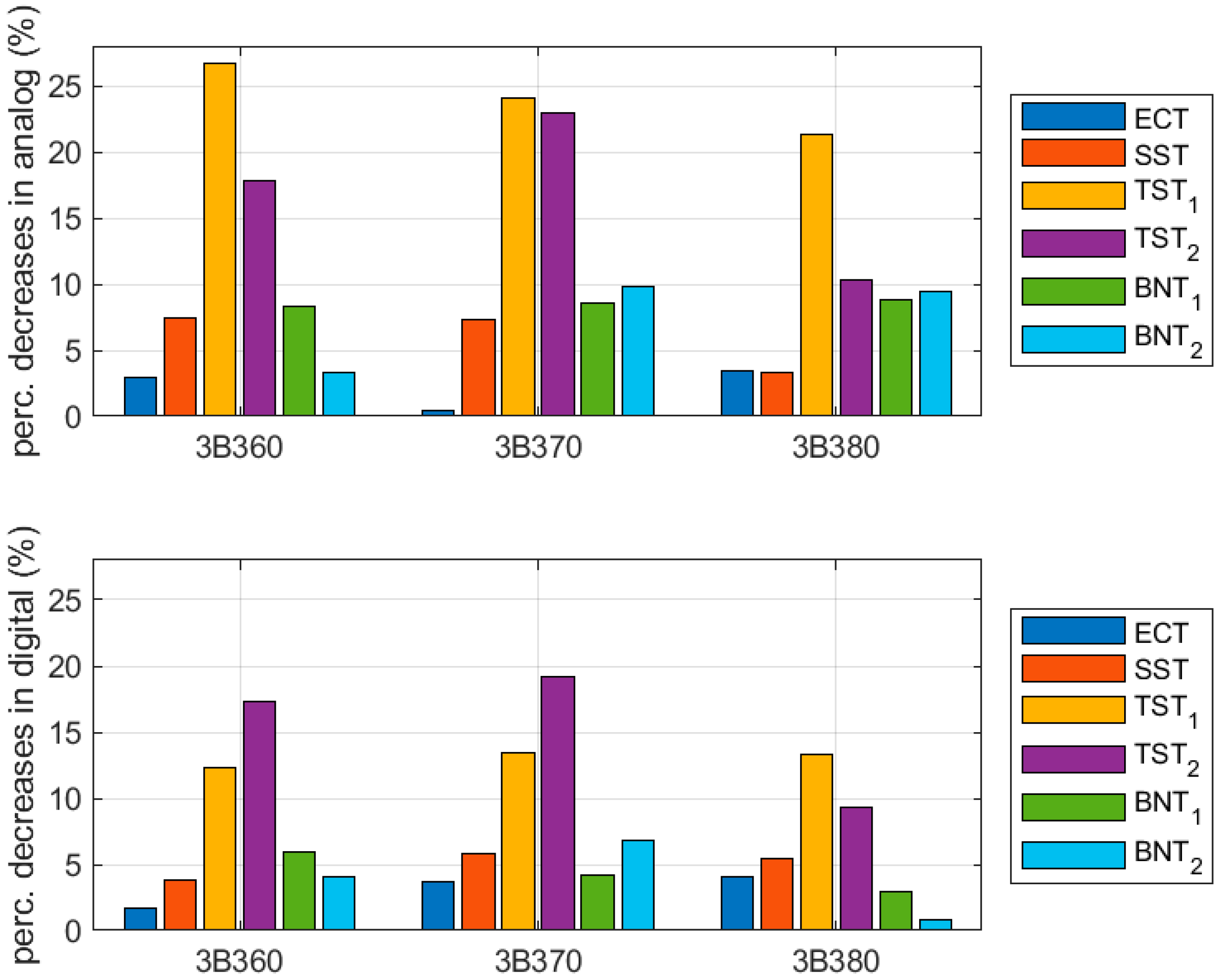
| Cardboard | Crease Lines | ECT (%) | SST (%) | TST1 (%) | TST2 (%) | BNT1 (%) | BNT2 (%) |
|---|---|---|---|---|---|---|---|
| B360 | analog | 2.99 | 7.43 | 26.7 | 17.7 | 8.26 | 3.34 |
| B370 | 0.42 | 7.29 | 24.0 | 22.8 | 8.62 | 9.82 | |
| B380 | 3.48 | 3.29 | 21.3 | 10.2 | 8.81 | 9.42 | |
| B360 | digital | 1.71 | 3.76 | 12.3 | 17.2 | 5.99 | 4.04 |
| B370 | 3.68 | 5.81 | 13.3 | 19.1 | 4.18 | 6.76 | |
| B380 | 4.03 | 5.47 | 13.3 | 9.28 | 2.90 | 0.85 |
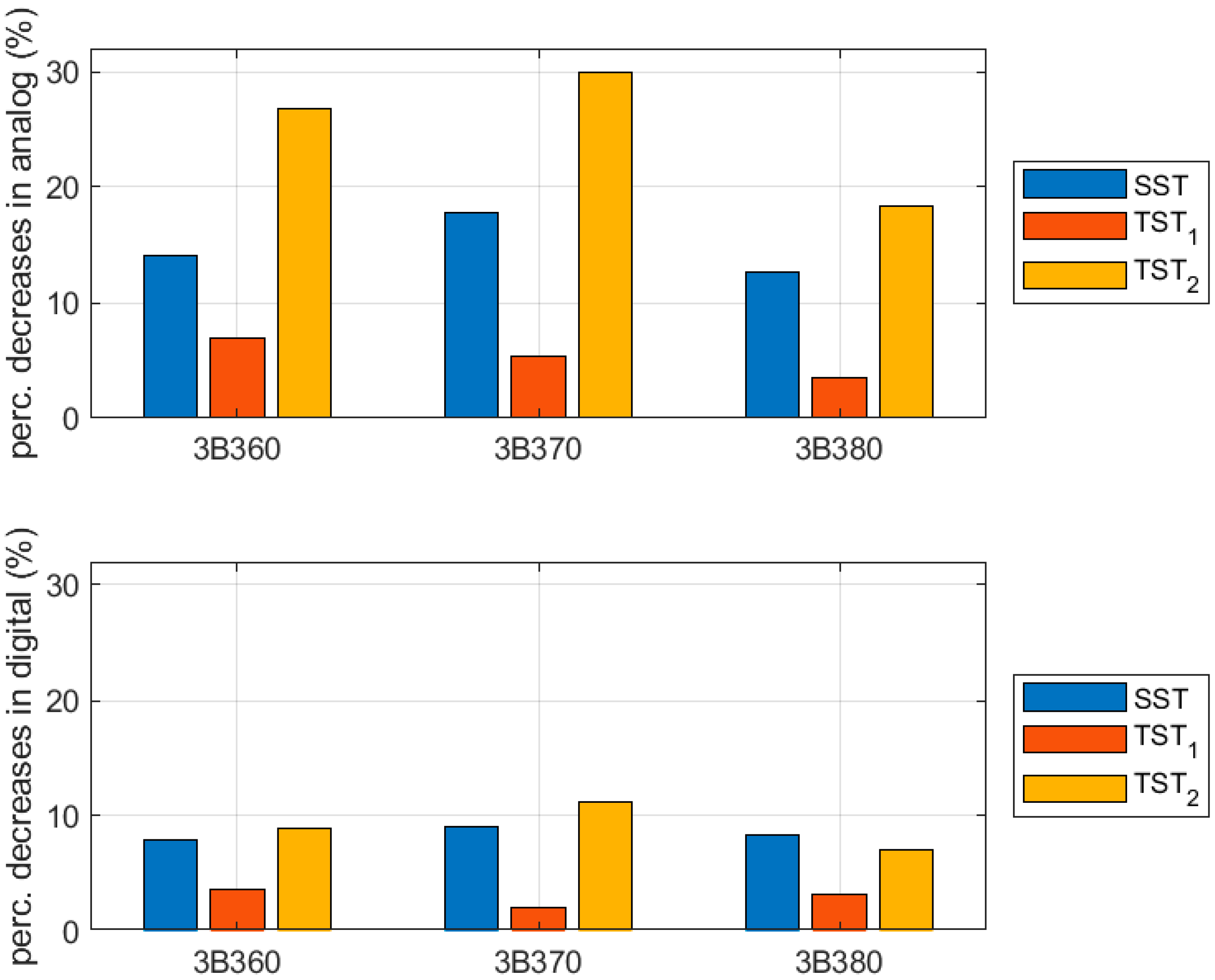
| Cardboard | Crease Lines | SST (%) | TST1 (%) | TST2 (%) |
|---|---|---|---|---|
| B360 | analog | 14.1 | 6.93 | 26.8 |
| B370 | 17.8 | 5.41 | 29.8 | |
| B380 | 12.6 | 3.51 | 18.3 | |
| B360 | digital | 7.93 | 3.65 | 8.89 |
| B370 | 9.01 | 2.05 | 11.2 | |
| B380 | 8.33 | 3.21 | 7.02 |
| Cardboard | Crease Lines | Compressive Strength (kN) |
|---|---|---|
| B360 | analog | 1.145 |
| B370 | 1.208 | |
| B380 | 0.963 (1.631) | |
| B360 | digital | 1.350 |
| B370 | 1.310 | |
| B380 | 0.990 (1.814) |
| Cardboard | Compressive Strength (%) |
|---|---|
| B360 | 18.0 |
| B370 | 8.43 |
| B380 | 2.77 (10.01) |
| Parameter | ||||
|---|---|---|---|---|
| (MPa) | 1831 | 1803 | 1811 | 1617 |
| (MPa) | 850 | 916 | 868 | 928 |
| (-) | 0.42 | 0.41 | 0.42 | 0.38 |
| (MPa) | 3362 | 2685 | 3566 | 2913 |
| (MPa) | 2.34 | 3.27 | 2.35 | 3.05 |
| (MPa) | 3.05 | 3.68 | 2.64 | 3.73 |
| (MPa) | 1.74 | 1.78 | 1.71 | 1.76 |
| 1, 0.73, 0.73 | 1, 0.75, 0.75 | 1, 0.52, 0.52 | 1, 0.62, 0.62 | |
| 0.46, 0.46, 0.46 | 0.5, 0.5, 0.5 | 0.36, 0.36, 0.36 | 0.41, 0.41, 0.41 |
| Cardboard | Crease Line | Compressive Strength (kN) | ||
|---|---|---|---|---|
| Experiment | ||||
| B360 | analog | 1.145 | B360 | analog |
| B370 | 1.208 | B370 | ||
| B380 | 1.631 | B380 | ||
| B360 | 1.350 | B360 | ||
| B370 | digital | 1.310 | B370 | digital |
| B380 | 1.814 | B380 | ||
| Cardboard | Crease Line | BCT Estimation Difference (%) | ||
|---|---|---|---|---|
| Experiment vs. Model A | ||||
| B360 | analog | 2.80 | B360 | analog |
| B370 | −3.78 | B370 | ||
| B380 | −2.32 | B380 | ||
| B360 | −2.97 | B360 | ||
| B370 | digital | −1.71 | B370 | digital |
| B380 | −4.19 | B380 | ||
Publisher’s Note: MDPI stays neutral with regard to jurisdictional claims in published maps and institutional affiliations. |
© 2022 by the authors. Licensee MDPI, Basel, Switzerland. This article is an open access article distributed under the terms and conditions of the Creative Commons Attribution (CC BY) license (https://creativecommons.org/licenses/by/4.0/).
Share and Cite
Garbowski, T.; Gajewski, T.; Knitter-Piątkowska, A. Influence of Analog and Digital Crease Lines on Mechanical Parameters of Corrugated Board and Packaging. Sensors 2022, 22, 4800. https://doi.org/10.3390/s22134800
Garbowski T, Gajewski T, Knitter-Piątkowska A. Influence of Analog and Digital Crease Lines on Mechanical Parameters of Corrugated Board and Packaging. Sensors. 2022; 22(13):4800. https://doi.org/10.3390/s22134800
Chicago/Turabian StyleGarbowski, Tomasz, Tomasz Gajewski, and Anna Knitter-Piątkowska. 2022. "Influence of Analog and Digital Crease Lines on Mechanical Parameters of Corrugated Board and Packaging" Sensors 22, no. 13: 4800. https://doi.org/10.3390/s22134800
APA StyleGarbowski, T., Gajewski, T., & Knitter-Piątkowska, A. (2022). Influence of Analog and Digital Crease Lines on Mechanical Parameters of Corrugated Board and Packaging. Sensors, 22(13), 4800. https://doi.org/10.3390/s22134800