
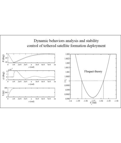
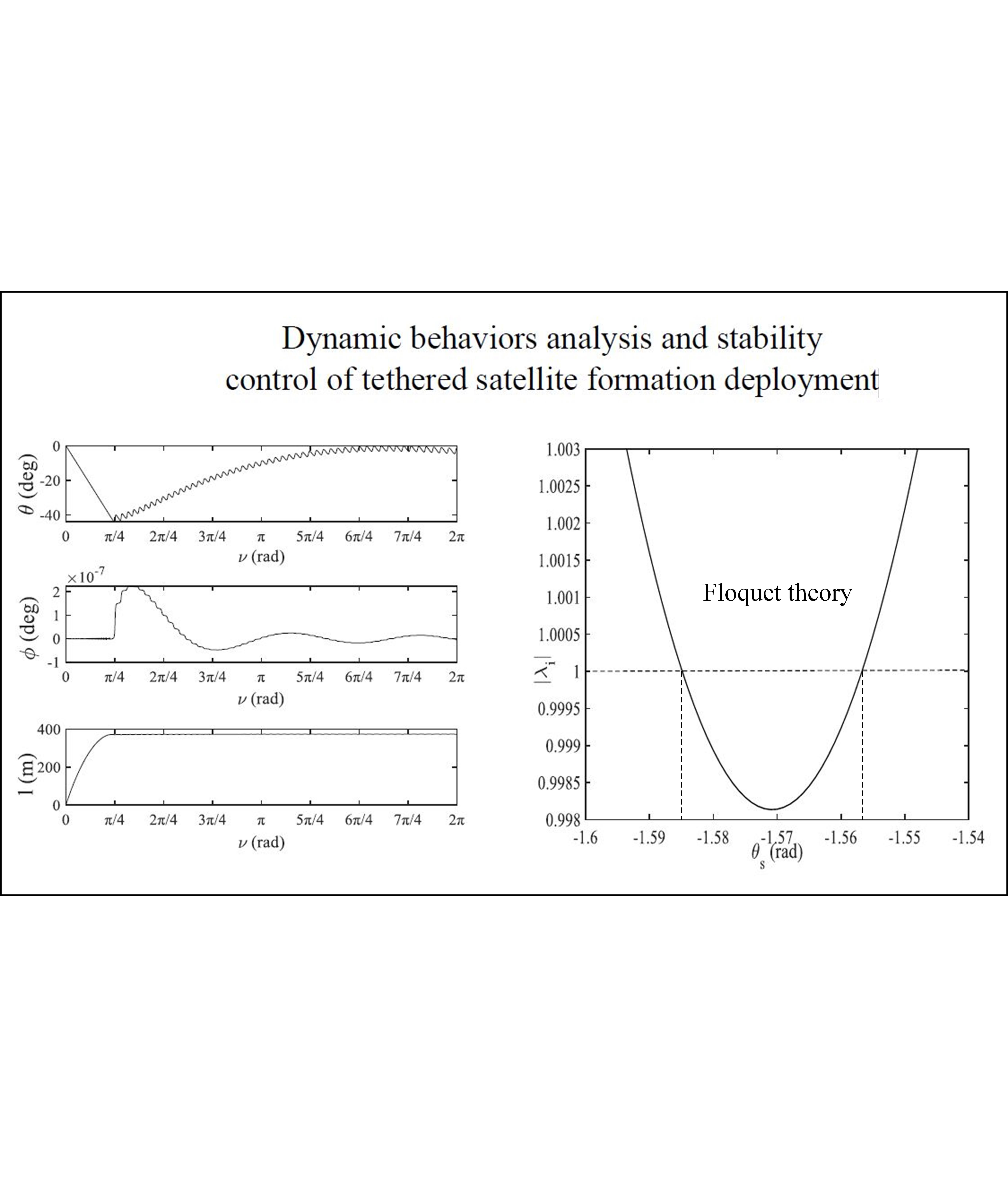
Dynamic Behavior Analysis and Stability Control of Tethered Satellite Formation Deployment


Abstract
:
1. Introduction
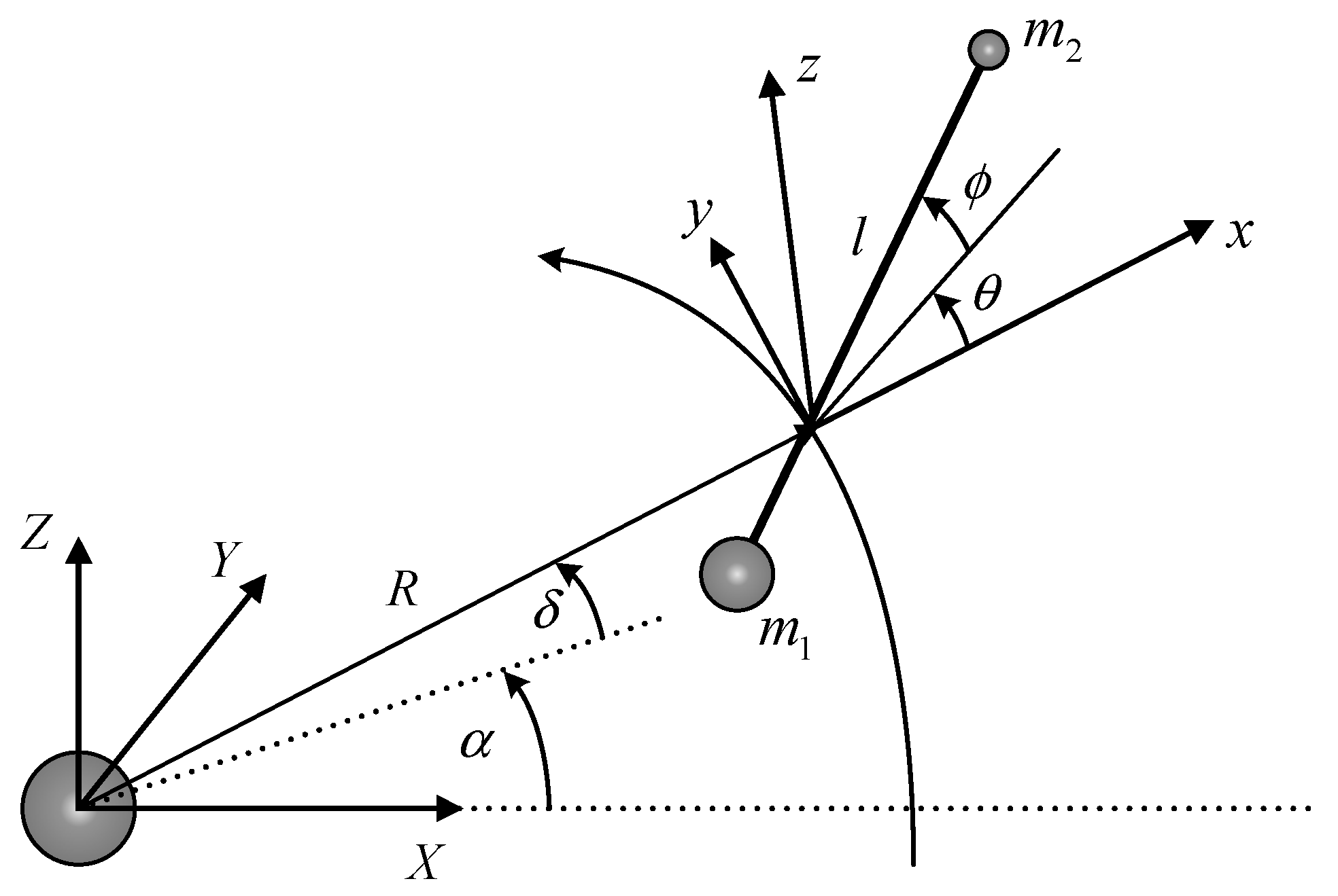
2. TSS Equations of Motion Using Lagrangian Method
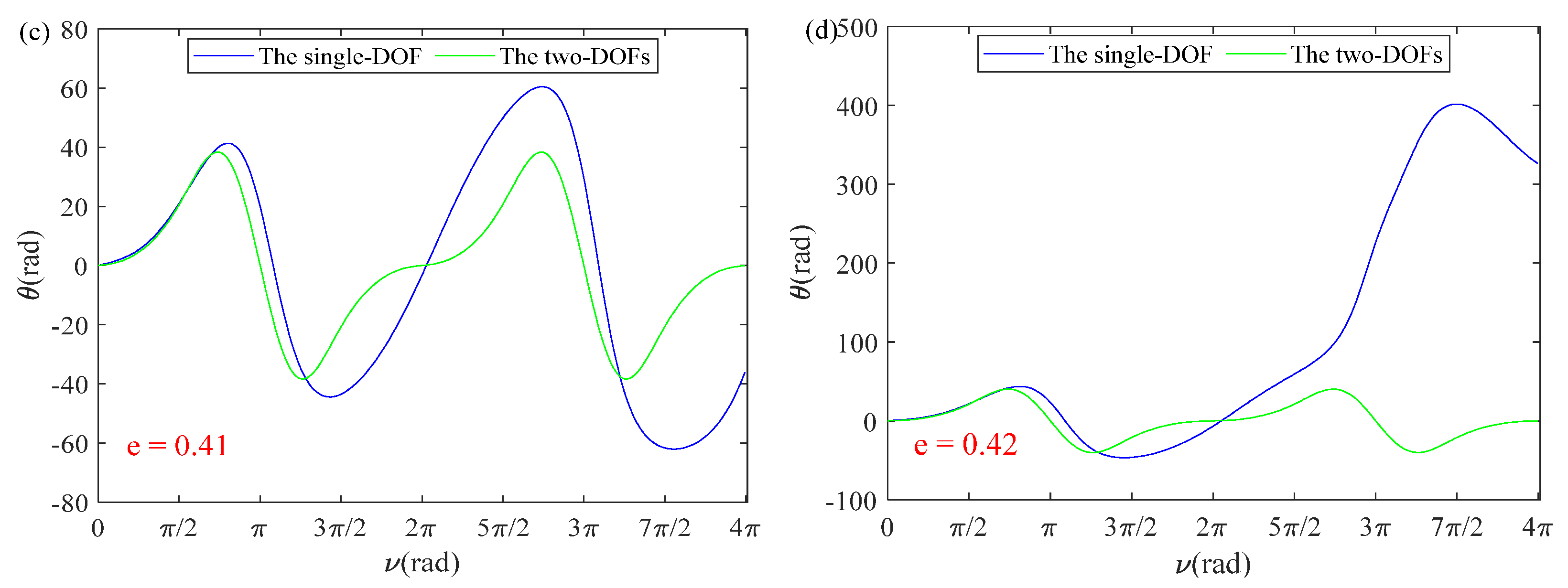
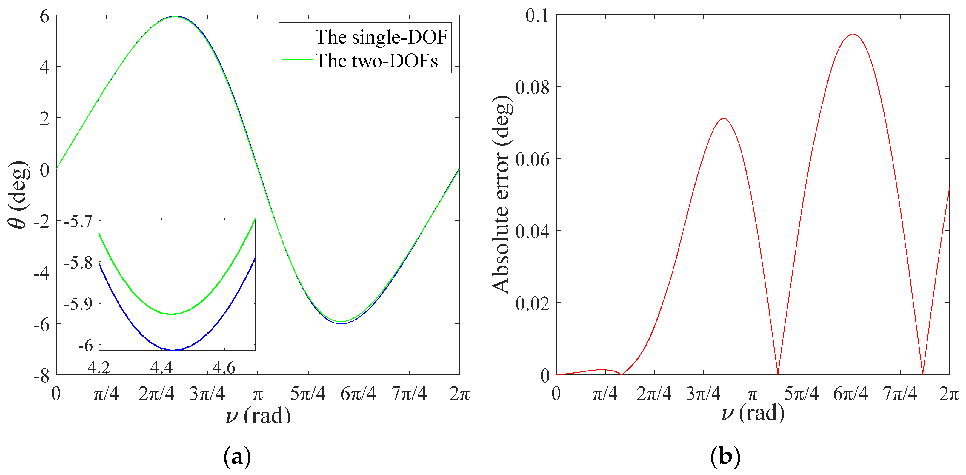
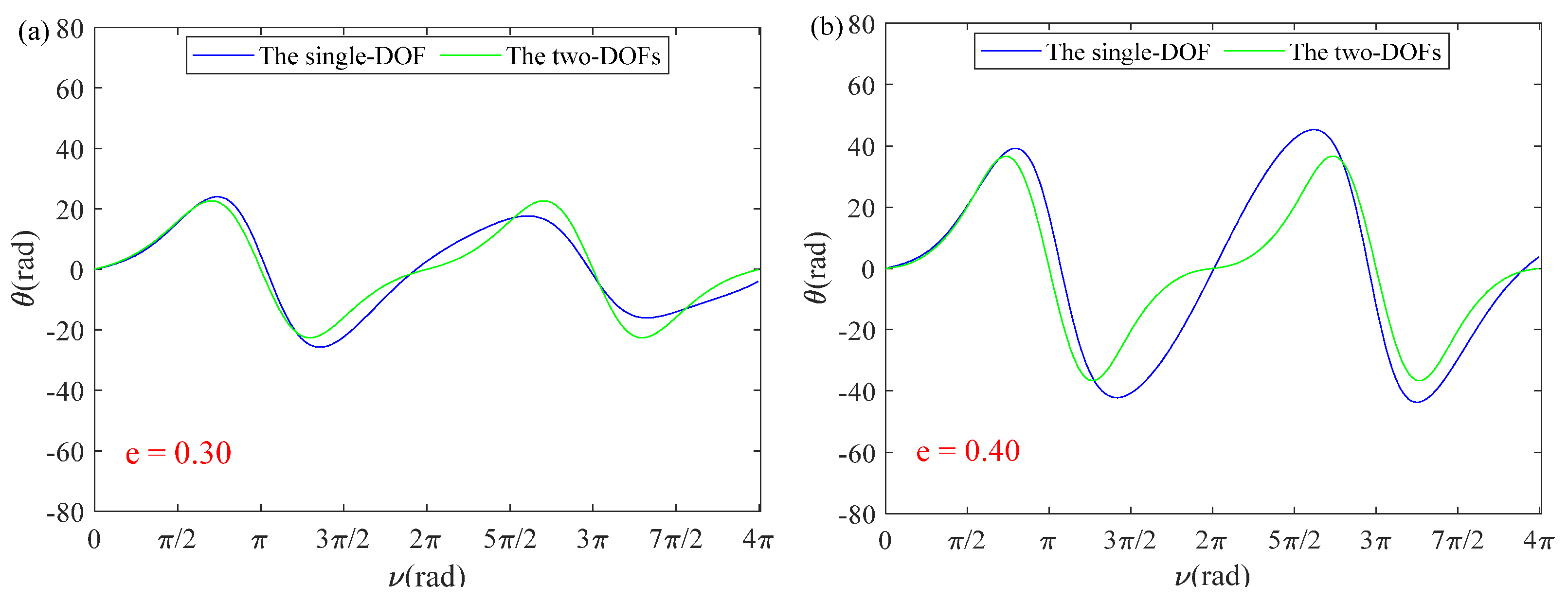
3. Dynamic Analysis of Simplified Models of Single-DOF and Two-DOFs
3.1. Single-DOF ()
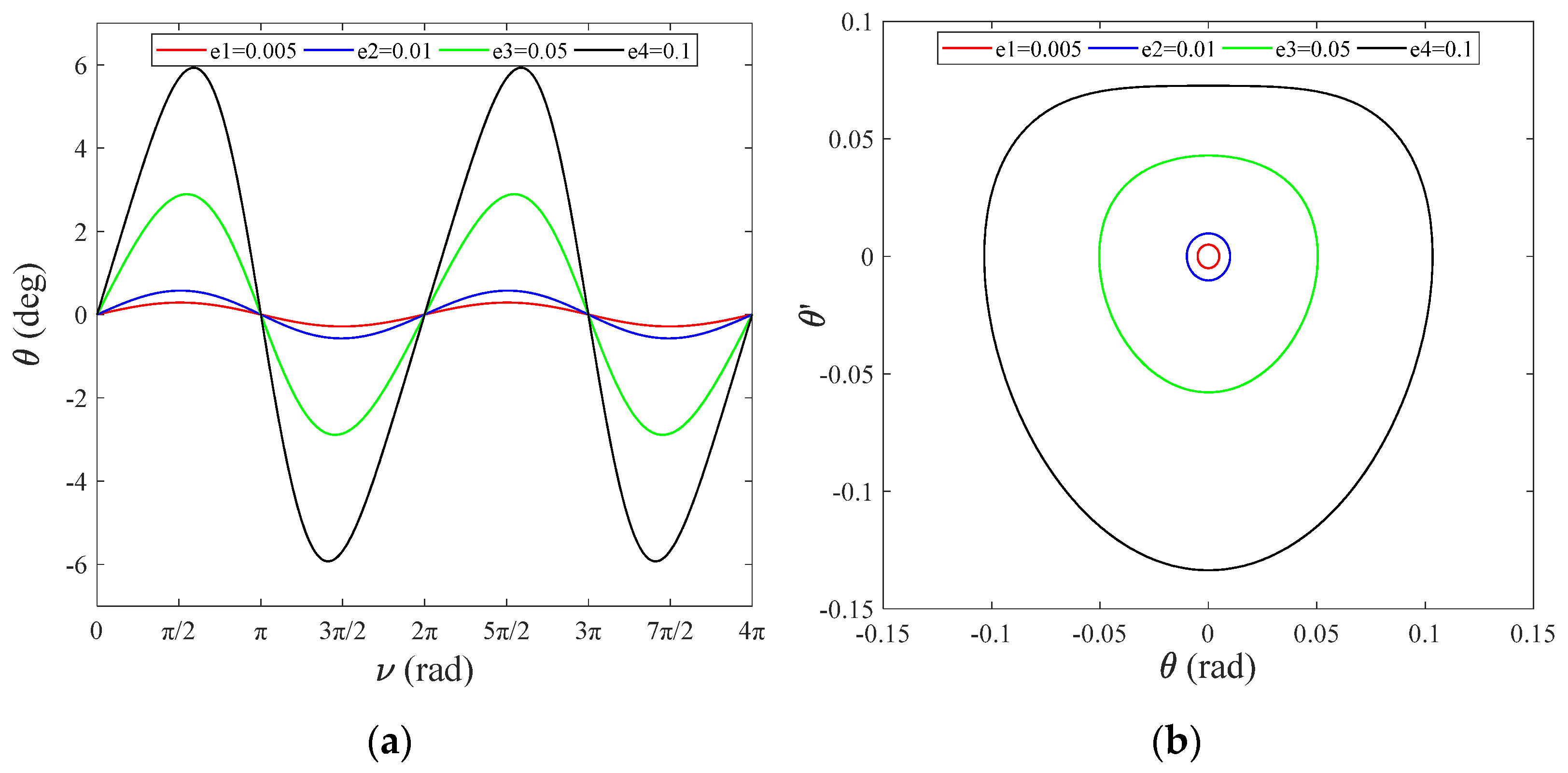
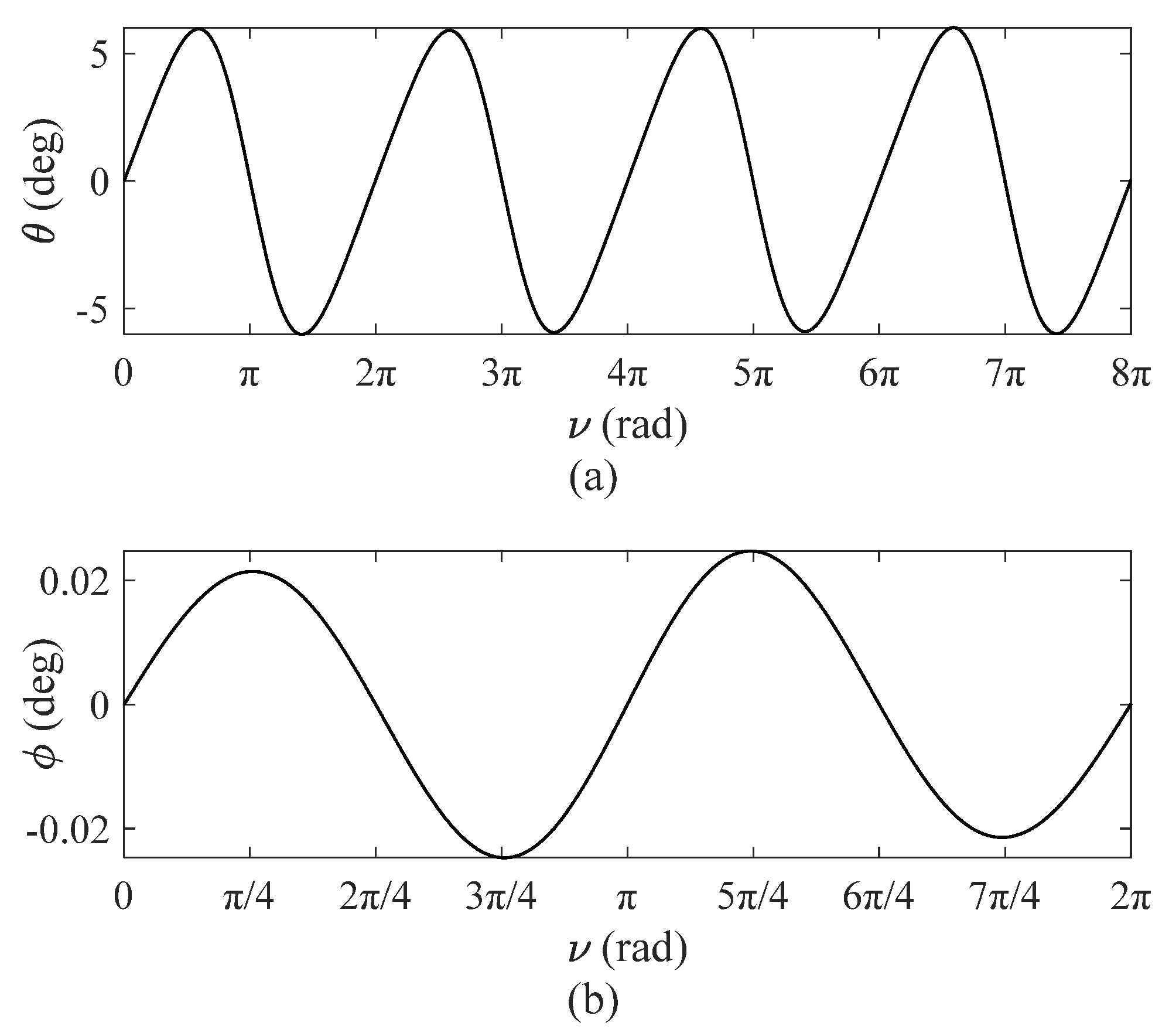
3.2. Two-DOFs ()
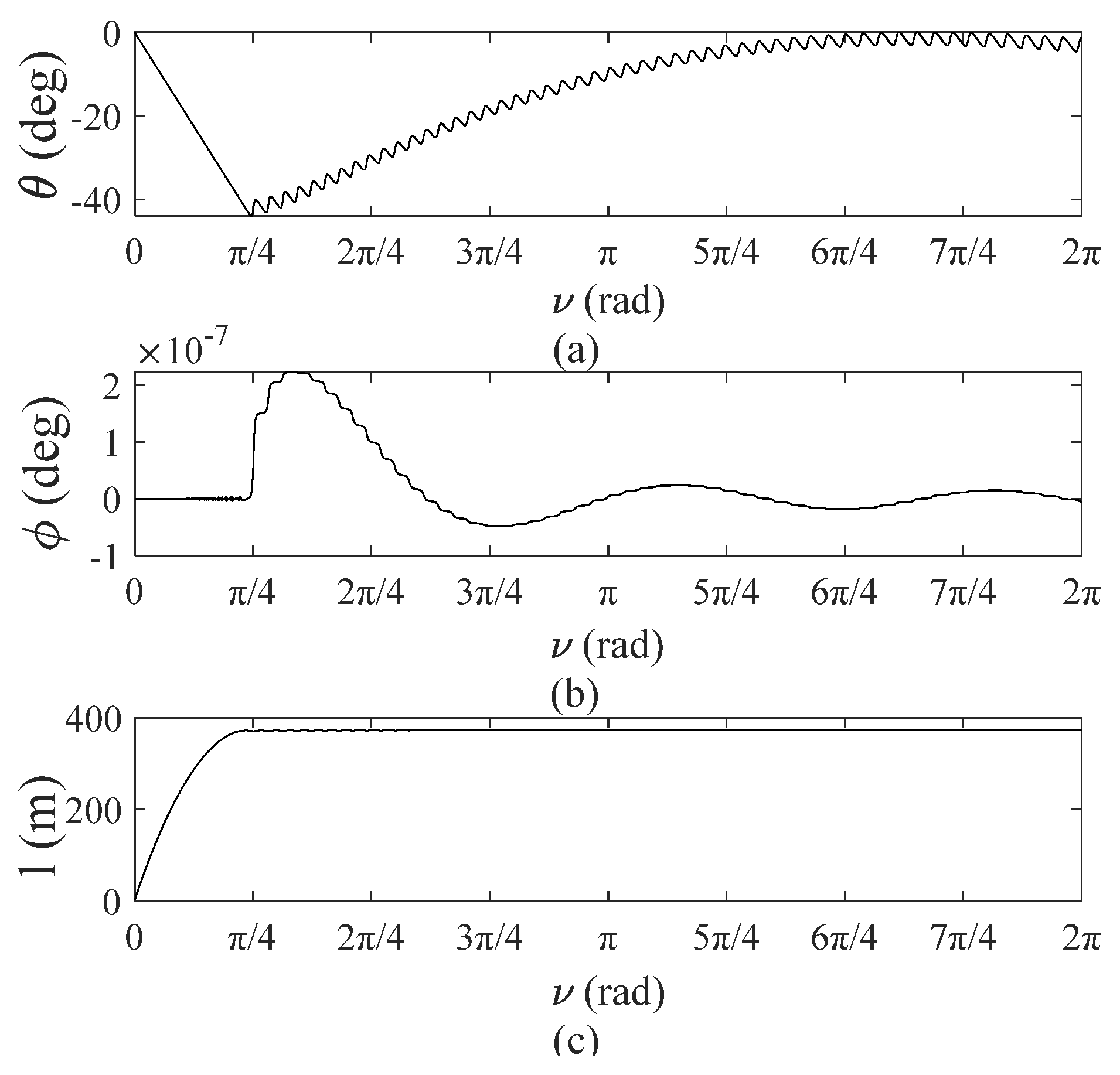
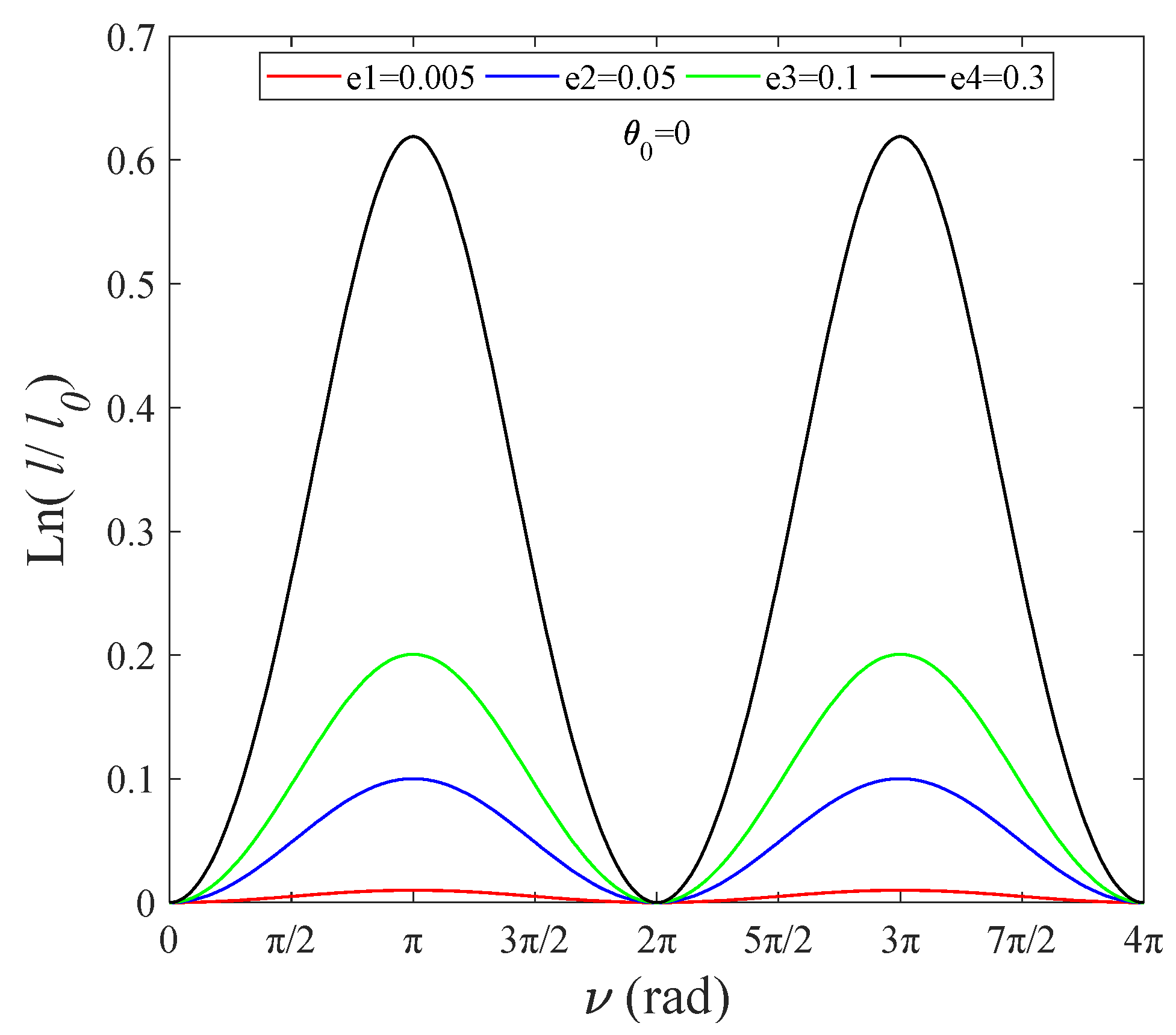
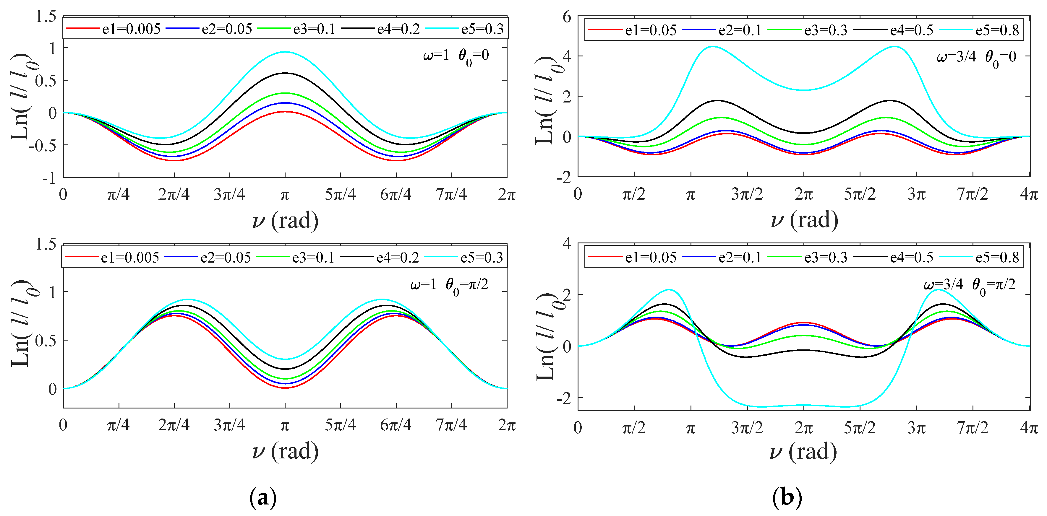
4. Stable Deployment Laws of Tether Release Rate and Tether Tension Control
4.1. Tether Release Rate Control
4.1.1. Fixed Angle
4.1.2. Fixed Angular Velocity
4.2. Tether Tension Control
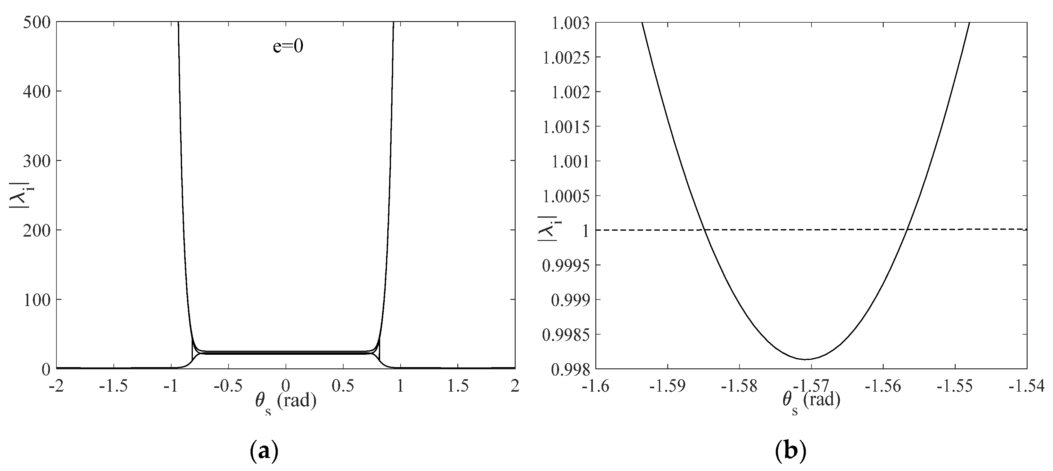
5. Stability Analysis of TSS Deployment Using Floquet Theory
6. Conclusions
Author Contributions
Funding
Institutional Review Board Statement
Informed Consent Statement
Data Availability Statement
Acknowledgments
Conflicts of Interest
References
- Wen, Y.L.; Zhu, J.; Gong, Y.X.; Wang, Q.; He, X.F. Distributed Orbit Determination for Global Navigation Satellite System with Inter-Satellite Link. Sensors 2019, 19, 1031. [Google Scholar] [CrossRef] [PubMed] [Green Version]
- Su, M.D.; Su, X.; Zhao, Q.L.; Liu, J.N. Bei-Dou Augmented Navigation from Low Earth Orbit Satellites. Sensors 2019, 19, 198. [Google Scholar] [CrossRef] [PubMed] [Green Version]
- Diakov, P.A.; Malashin, A.A.; Smirnov, N.N. Estimation of parameters of the space tethered system for stable load transportation along the tether. Acta Astronaut. 2021, 181, 602–605. [Google Scholar] [CrossRef]
- Pang, Z.J.; Wen, H.; Rui, X.T.; Du, Z.H. Nonlinear resonant analysis of space tethered satellite system in elliptical orbits. Acta Astronaut. 2021, 182, 264–273. [Google Scholar] [CrossRef]
- Hu, W.P.; Song, M.Z.; Deng, Z.C. Energy dissipation/transfer and stable attitude of spatial on-orbit tethered system. J. Sound Vib. 2018, 412, 58–73. [Google Scholar] [CrossRef]
- Kong, X.R.; Xu, D.F. Summary of research on space tether system. Space Environ. Eng. 2010, 27, 775–783. [Google Scholar]
- Cartmell, M.P.; McKenzie, D.J. A review of space tether research. Prog. Aerosp. Sci. 2008, 44, 1–21. [Google Scholar] [CrossRef]
- Yu, S.H. Space microgravity combination and its control. Chin. Space Sci. Technol. 2019, 39, 49–54. [Google Scholar]
- Chen, M.H.; Goyal, R.; Majji, M.; Skelton, R.E. Review of space habitat designs for long term space explorations. Prog. Aerosp. Sci. 2021, 122, 100692. [Google Scholar] [CrossRef]
- Sun, L.; Zhao, G.; Huang, H. Optimal control scheme of the tethered system for orbital transfer under a constant thrust. Int. J. Aerosp. Eng. 2018, 2018, 1572726. [Google Scholar] [CrossRef]
- Benvenuto, R.; Salvi, S.; Lavagna, M. Dynamics analysis and GNC design of flexible systems for space debris active removal. Acta Astronaut. 2015, 110, 247–265. [Google Scholar] [CrossRef]
- Razzaghi, P.; Khatib, E.A.; Bakhtiari, S. Real time control of tethered satellite systems to de-orbit space debris. Aerosp. Sci. Technol. 2021, 109, 106379. [Google Scholar] [CrossRef]
- Guo, J.F.; Wang, B.; Tan, C.L. Progress in flexible acquisition of non-cooperative objects in space. J. Aerosp. 2020, 41, 125–135. [Google Scholar]
- Zhu, Z.C.; Yang, G.Q.; Yu, J.P. The development of micro-satellite network and formation technologies. Aerosp. Shanghai 2004, 6, 46–49. [Google Scholar]
- Cai, Z.Q.; Li, X.F.; Wu, Z.G. Deployment and retrieval of a rotating triangular tethered satellite formation near libration points. Acta Astronaut. 2014, 98, 37–49. [Google Scholar] [CrossRef]
- Kumar, D.K. Review on dynamics and control of nonelectrodynamic tethered satellite systems. J. Spacecr. Rockets 2006, 43, 705–720. [Google Scholar] [CrossRef]
- Krishnamurthy, K.; Chao, M.C. Active vibration control during deployment of space structures. J. Sound Vib. 1992, 152, 205–218. [Google Scholar] [CrossRef]
- Takeichi, N.; Tachibana, N. A tethered plate satellite as a sweeper of small space debris. Acta Astronaut. 2021, 189, 429–436. [Google Scholar] [CrossRef]
- Pang, Z.J.; Jin, D.P.; Yu, B.S.; Wen, H. Nonlinear normal modes of a tethered satellite system of two degrees of freedom under internal resonances. Nonlinear Dyn. 2016, 85, 1779–1789. [Google Scholar] [CrossRef]
- Zhao, G.W.; Sun, L.; Huang, H.; Geng, L. Optimal attitude control of a tethered system for noncoplanar orbital transfer under a constant thrust. IEEE Trans. Aerosp. Electron. Syst. 2020, 56, 1844–1855. [Google Scholar] [CrossRef]
- Williams, P. Libration control of electrodynamic tethers using predictive control with time-delayed feedback. J. Guid. Control Dyn. 2009, 32, 1254–1268. [Google Scholar] [CrossRef]
- Williams, P. Spacecraft Rendezvous on Small Relative Inclination Orbits Using Tethers. J. Spacecr. Rockets 2005, 42, 1047–1060. [Google Scholar] [CrossRef]
- Pradeep, S.; Kumar, K. Extension of tethered satellites in the atmosphere. Acta Astronaut. 2003, 52, 1–10. [Google Scholar] [CrossRef]
- Luongo, A.; Vestroni, F. Non-linear free periodic oscillations of a tethered satellite system. J. Sound Vib. 1994, 175, 299–315. [Google Scholar] [CrossRef] [Green Version]
- Yu, B.S.; Huang, Z.; Geng, L.L. Stability and ground experiments of a spinning triangular tethered satellite formation on a low earth orbit. Aerosp. Sci. Technol. 2019, 92, 595–604. [Google Scholar] [CrossRef]
- Yu, B.S.; Jin, D.P.; Wen, H. Analytical deployment control law for a flexible tethered satellite system. Aerosp. Sci. Technol. 2017, 66, 294–303. [Google Scholar] [CrossRef]
- Ellis, J.R.; Hall, C.D. Out-of-plane librations of spinning tethered satellite systems. Celest. Mech. Dyn. Astron. 2010, 106, 39–67. [Google Scholar] [CrossRef]
- Zhou, J.; Chang, Y. Optimal multiimpulse rendezvous in an elliptic orbit with different plane affected by the Earth’s oblateness J2 perturbation. J. Aerosp. 2008, 29, 472–475. [Google Scholar]
- Becker, M.; Stoll, E.; Retat, I. Influence of orbital perturbations on tethered space systems for active debris removal missions. In Proceedings of the 7th European Conference on Space Debris, Darmstadt, Germany, 18–21 April 2017. [Google Scholar]
- Luo, C.Q.; Wen, H.; Jin, D.P. Deployment of flexible space tether system with satellite attitude stabilization. Acta Astronaut. 2019, 160, 240–250. [Google Scholar] [CrossRef]
- Darabi, A.; Assadian, N. Coupled rotational and translational modeling of two satellites connected by a tether and their robust attitude control using optimal offset approach. Adv. Space Res. 2019, 63, 2455–2468. [Google Scholar] [CrossRef]
- Yao, F.Z.; Shi, A.R. Dynamic Analysis of Rope Satellite Deployment Phase. Flight Control Detect. 2019, 2, 33–40. [Google Scholar]
- Williams, P. Deployment/retrieval optimization for flexible tethered satellite systems. Nonlinear Dyn. 2008, 52, 159–179. [Google Scholar] [CrossRef]
- Liu, H.L.; He, Y.Z.; Yan, H.; Tan, S.P. Tether tension control law design during orbital transfer via small-gain theorem. Aerosp. Sci. Technol. 2017, 63, 191–202. [Google Scholar] [CrossRef]
- Williams, P.; Hyslop, A.; Stelzer, M. YES2 optimal trajectories in presence of eccentricity and aerodynamic drag. Acta Astronaut. 2009, 64, 745–769. [Google Scholar] [CrossRef]


| Parameters | Value |
|---|---|
| Minimal tension as a result of friction, T0 | 0.01 N |
| Inertial multiplier, I | 3.1 |
| 0.89 | |
| Area exponent, E | 1.4 |
| 0.18 | |
| 0 | |
| 0.05 | |
| 1.9 |
| Parameters | Value |
|---|---|
| Mother satellite mass, m1 | 6530 kg |
| Subsatellite mass, m2 | 12 kg |
| Tether diameter, d | 5 × 10⁻⁴ m |
| Reference tether length, L | 3500 m |
| Tether line density, ρ | 1.85 × 10⁻⁴ kg/m |
| Orbit eccentricity, e | 0.0027 |
| Orbital semi-major axis, a | 6.645 × 10⁶ m |
| 3.986 × 10¹⁴ m3/s2 |
Publisher’s Note: MDPI stays neutral with regard to jurisdictional claims in published maps and institutional affiliations. |
© 2021 by the authors. Licensee MDPI, Basel, Switzerland. This article is an open access article distributed under the terms and conditions of the Creative Commons Attribution (CC BY) license (https://creativecommons.org/licenses/by/4.0/).
Share and Cite
Zhang, K.; Lu, K.; Gu, X.; Fu, C.; Zhao, S. Dynamic Behavior Analysis and Stability Control of Tethered Satellite Formation Deployment. Sensors 2022, 22, 62. https://doi.org/10.3390/s22010062
Zhang K, Lu K, Gu X, Fu C, Zhao S. Dynamic Behavior Analysis and Stability Control of Tethered Satellite Formation Deployment. Sensors. 2022; 22(1):62. https://doi.org/10.3390/s22010062
Chicago/Turabian StyleZhang, Kangyu, Kuan Lu, Xiaohui Gu, Chao Fu, and Shibo Zhao. 2022. "Dynamic Behavior Analysis and Stability Control of Tethered Satellite Formation Deployment" Sensors 22, no. 1: 62. https://doi.org/10.3390/s22010062
APA StyleZhang, K., Lu, K., Gu, X., Fu, C., & Zhao, S. (2022). Dynamic Behavior Analysis and Stability Control of Tethered Satellite Formation Deployment. Sensors, 22(1), 62. https://doi.org/10.3390/s22010062