
Secure LoRa Firmware Update with Adaptive Data Rate Techniques †


Abstract
1. Introduction
1.1. Background
1.2. Contributions and Outline
- A method is proposed for energy optimized firmware updates for mobile LoRa devices that is both secure and reliable.
- The method is designed to work in LoRa ad-hoc networks without LoRaWAN.
- The method leverages LoRa ADR techniques to minimize energy consumption by reducing the firmware image receive time.
- A battery consumption approximation technique is provided to quantify the process energy expenditure.
- A security assessment is performed to evaluate privacy and authenticity.
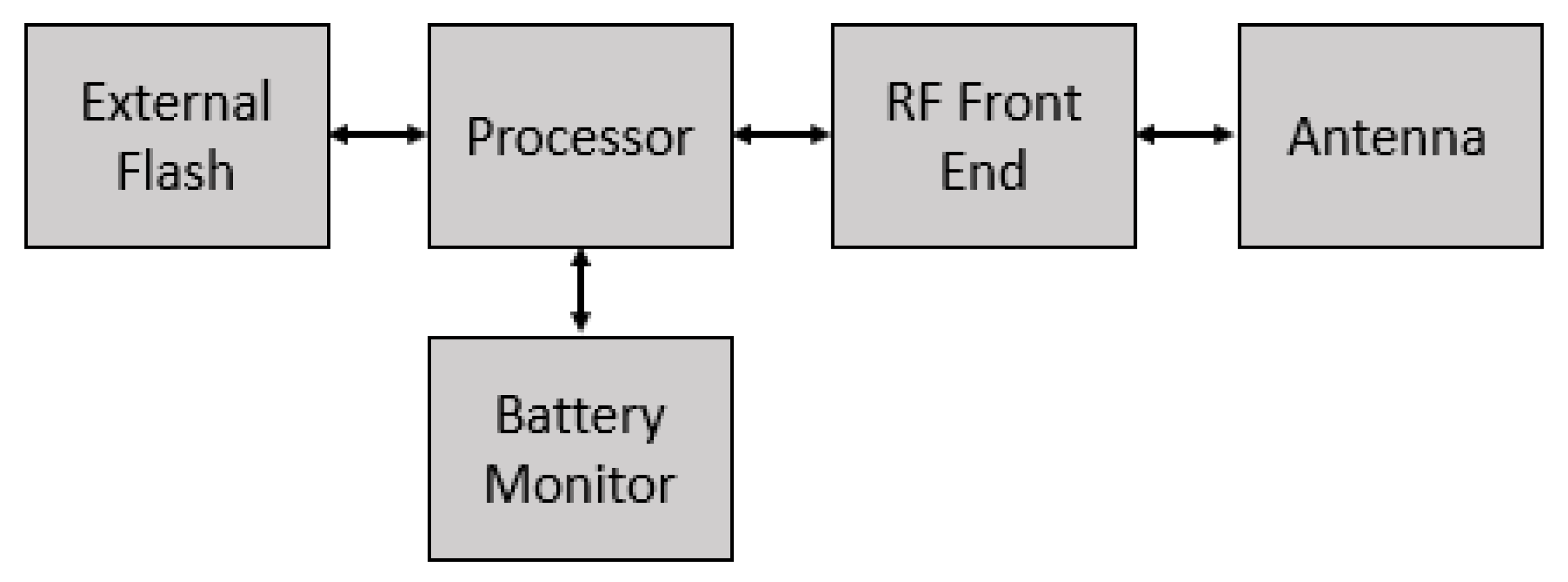
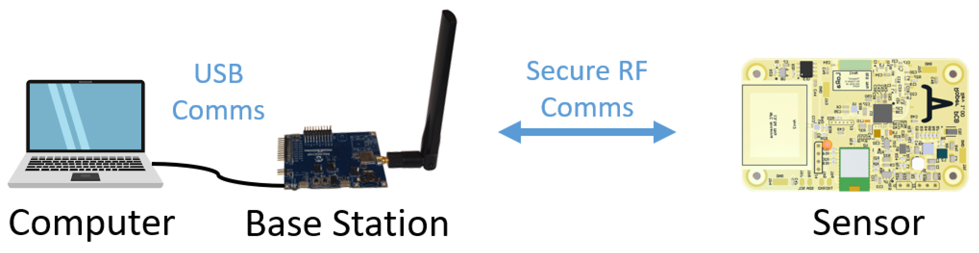
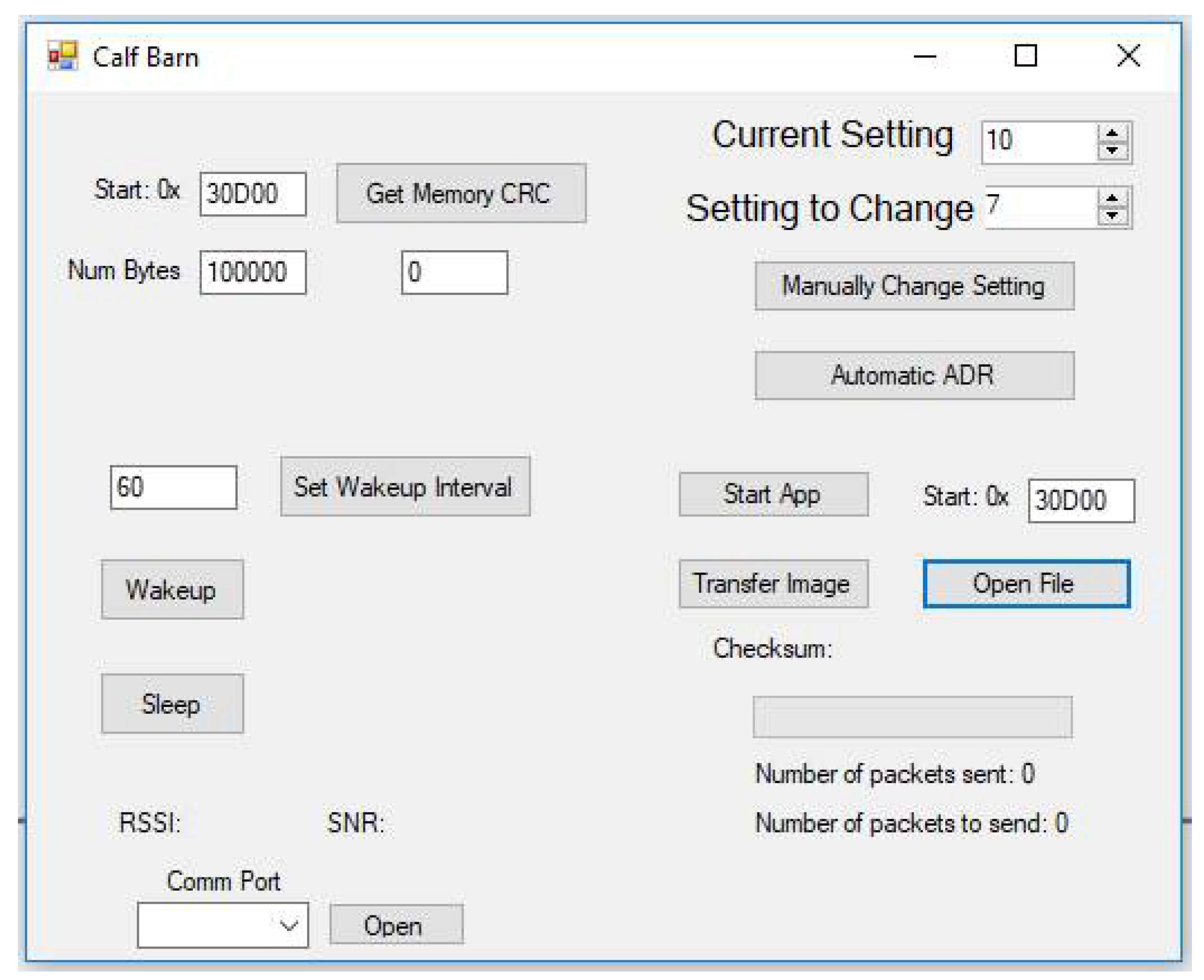
2. Materials and Methods
- Initial Exchange: Establishes status and general configuration information.
- ADR Rate Optimization: Finds the optimal communication setting with which to exchange the firmware.
- Battery Approximation: Estimates total energy consumption for completing the update process and terminates the process if the battery capacity is insufficient.
- Firmware Transfer: Transfers the encrypted firmware image over the RF link.
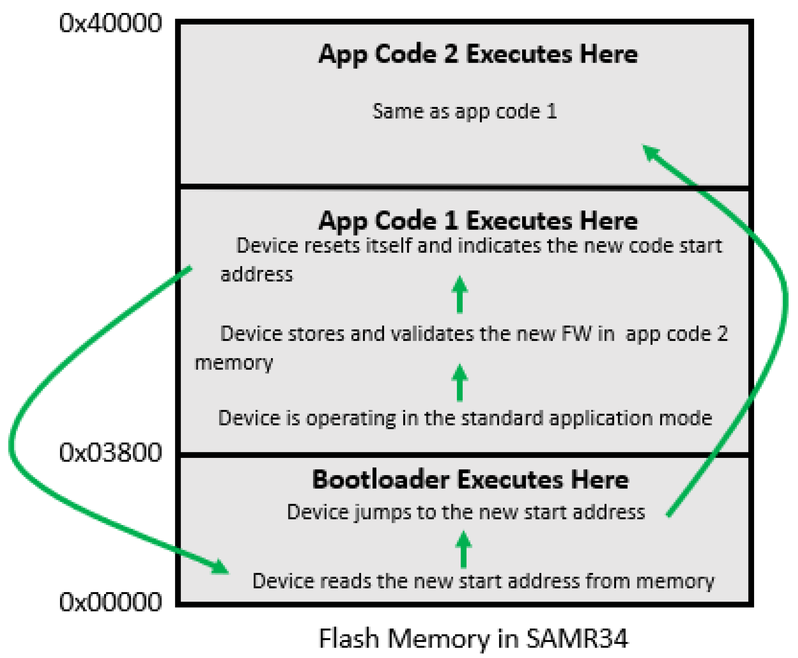
- Commit Code to Flash: After confirming that the firmware image is valid, the application hands control over to the boot loader to load the new application code, and then returns control to the new application.
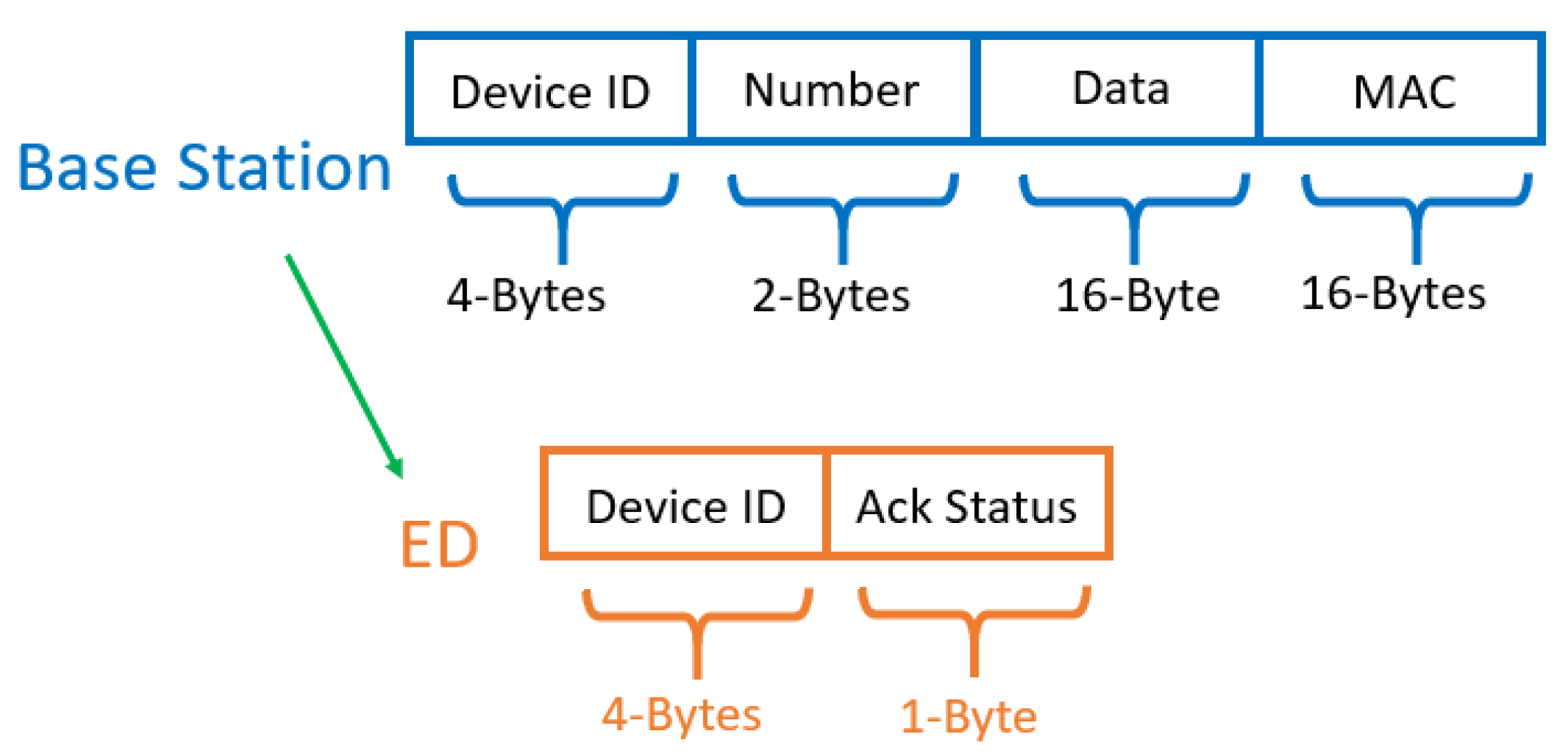
2.1. Initial Exchange
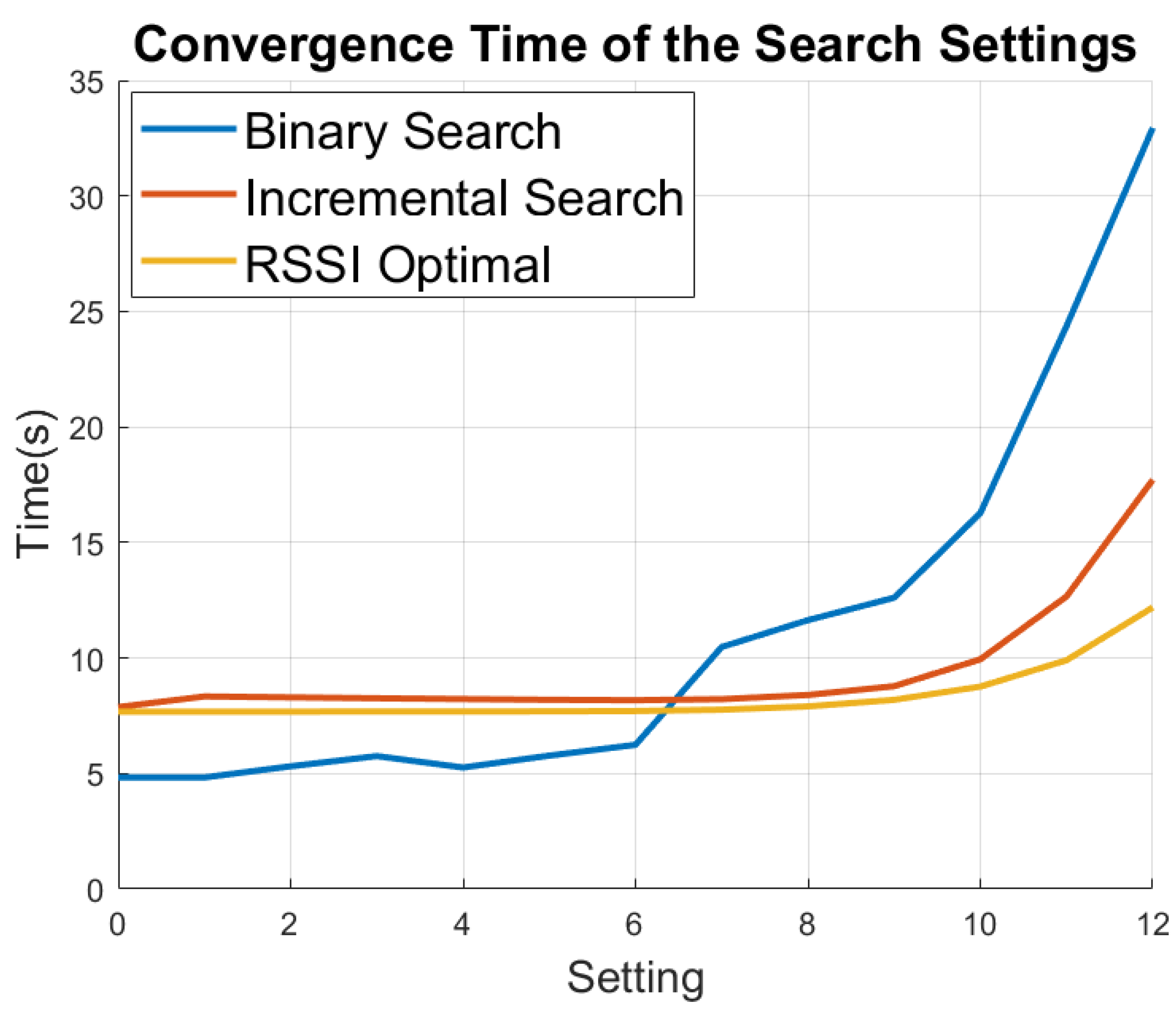
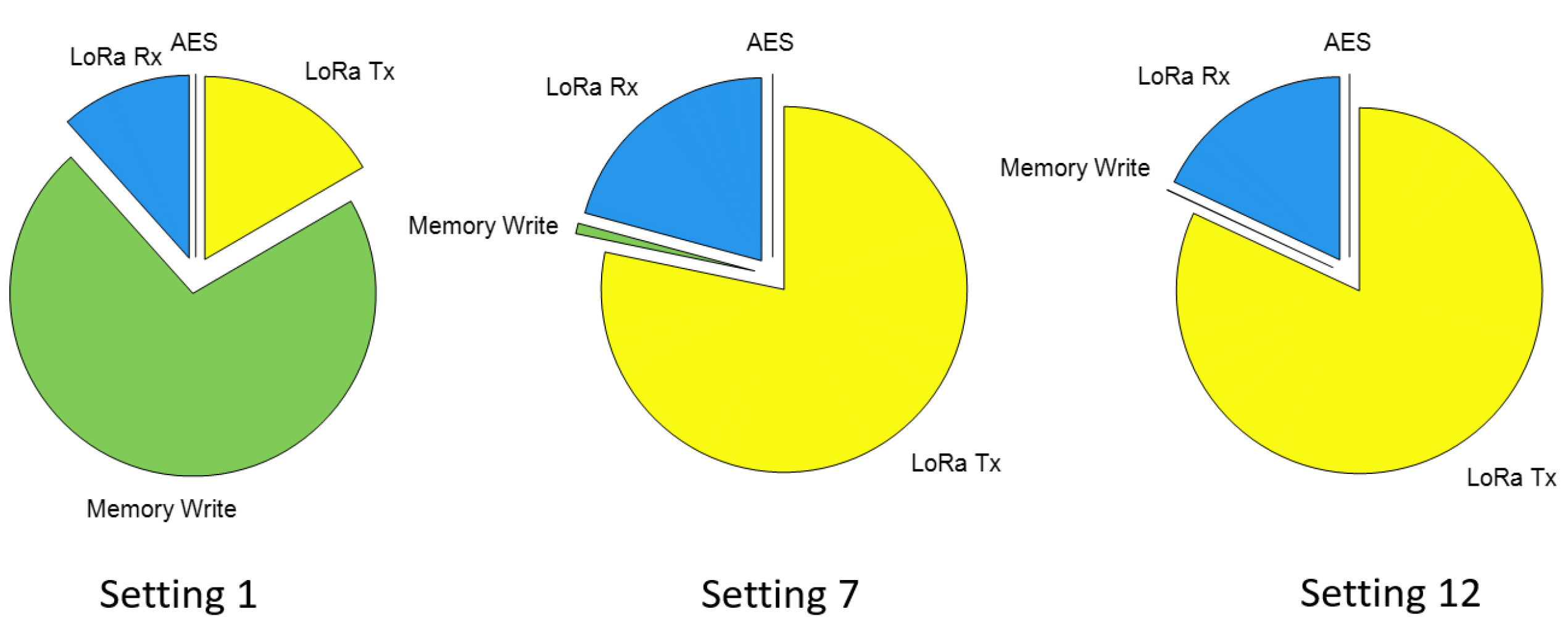
2.2. ADR Techniques
2.3. Battery Approximation
2.4. Firmware Transfer
2.5. Committing Code to Flash
3. Results
3.1. Functional Characterization
3.2. Simulation
3.3. Implementation
4. Discussion
4.1. Security Assessment
4.2. Conclusions and Future Work
Author Contributions
Funding
Institutional Review Board Statement
Informed Consent Statement
Data Availability Statement
Acknowledgments
Conflicts of Interest
References
- Mekki, K.; Bajic, E.; Chaxel, F.; Meyer, F. A comparative study of LPWAN technologies for large-scale IoT deployment. ICT Express 2019, 5, 1–7. [Google Scholar] [CrossRef]
- SX1276/77/78/79—137 MHz to 1020 MHz Low Power Long Range Transceiver; Datasheet, Rev. 4; Semtech Corporation: Camarillo, CA, USA, 2015; pp. 1–115.
- Butun, I.; Pereira, N.; Gidlund, M. Security risk analysis of LoRaWAN and future directions. Future Internet 2019, 11, 3. [Google Scholar] [CrossRef]
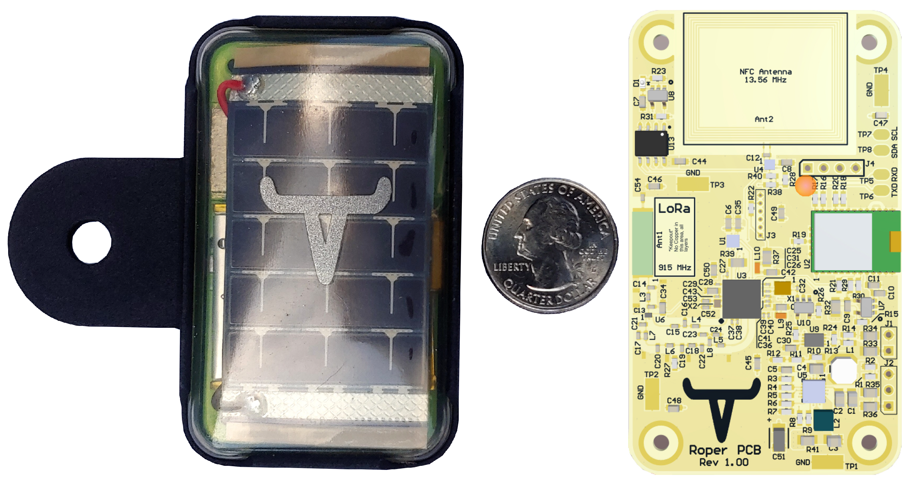
- Roper. Revolutionizing Beef Production. Available online: https://www.ropertag.com/ (accessed on 1 January 2021).
- Centelles, R.P.; Freitag, F.; Meseguer, R.; Navarro, L.; Ochoa, S.F.; Santos, R.M. A LoRa-Based Communication System for Coordinated Response in an Earthquake Aftermath. In Proceedings of the 13th International Conference on Ubiquitous Computing and Ambient Intelligence UCAml, Toledo, Spain, 2–5 December 2019. [Google Scholar]
- Germani, L.; Mecarelli, V.; Baruffa, G.; Rugini, L.; Frescura, F. An IoT Architecture for Continuous Livestock Monitoring Using LoRa LPWAN. Electronics 2019, 8, 1435. [Google Scholar] [CrossRef]
- Sharma, V.; You, I.; Pau, G.; Collotta, M.; Lim, J.D.; Kim, J.N. LoRaWAN-based energy-efficient surveillance by drones for intelligent transportation systems. Energies 2018, 11, 573. [Google Scholar] [CrossRef]
- Bor, M.C.; Roedig, U.; Voigt, T.; Alonso, J.M. Do LoRa low-power wide-area networks scale? In Proceedings of the 19th ACM International Conference on Modeling, Analysis and Simulation of Wireless and Mobile Systems, Malta, Malta, 22–24 November 2016; pp. 59–67. [Google Scholar]
- Bor, M.; Roedig, U. LoRa transmission parameter selection. In Proceedings of the 2017 13th International Conference on Distributed Computing in Sensor Systems (DCOSS), Ottawa, ON, Canada, 5–7 June 2017; pp. 27–34. [Google Scholar]
- Velde, B. Multi-Hop Lorawan: Including a Forwarding Node. Semantic Scholar, 2017, Corpus ID: 85465247. Available online: https://www.semanticscholar.org/paper/Multi-hop-LoRaWAN-%3A-including-a-forwarding-node-Velde/7969ab3473c910333d7fc2dc633aebddc3cab5bb (accessed on 30 March 2021).
- Dias, J.; Grilo, A. LoRaWAN multi-hop uplink extension. Procedia Comput. Sci. 2018, 130, 424–431. [Google Scholar] [CrossRef]
- Bouguera, T.; Diouris, J.F.; Chaillout, J.J.; Jaouadi, R.; Andrieux, G. Energy consumption model for sensor nodes based on LoRa and LoRaWAN. Sensors 2018, 18, 2104. [Google Scholar] [CrossRef] [PubMed]
- Casals, L.; Mir, B.; Vidal, R.; Gomez, C. Modeling the energy performance of LoRaWAN. Sensors 2017, 17, 2364. [Google Scholar] [CrossRef] [PubMed]
- Slabicki, M.; Premsankar, G.; Di Francesco, M. Adaptive configuration of LoRa networks for dense IoT deployments. In Proceedings of the NOMS 2018-2018 IEEE/IFIP Network Operations and Management Symposium, Taipei, Taiwan, 23–27 April 2018; pp. 1–9. [Google Scholar]
- Kim, S.; Yoo, Y. Contention-aware adaptive data rate for throughput optimization in LoRaWAN. Sensors 2018, 18, 1716. [Google Scholar] [CrossRef] [PubMed]
- Hauser, V.; Hégr, T. Proposal of adaptive data rate algorithm for lorawan-based infrastructure. In Proceedings of the 2017 IEEE 5th International Conference on Future Internet of Things and Cloud (FiCloud), Prague, Czech Republic, 21–23 August 2017; pp. 85–90. [Google Scholar]
- Li, S.; Raza, U.; Khan, A. How agile is the adaptive data rate mechanism of LoRaWAN? In Proceedings of the 2018 IEEE Global Communications Conference (GLOBECOM), Abu Dhabi, United Arab Emirates, 9–13 December 2018; pp. 206–212. [Google Scholar]
- Kousias, K.; Caso, G.; Alay, Ö.; Lemic, F. Empirical analysis of lorawan adaptive data rate for mobile internet of things applications. In Proceedings of the 2019 on Wireless of the Students, by the Students, and for the Students Workshop, Los Cabos, Mexico, 19–21 October 2019; pp. 9–11. [Google Scholar]
- Heeger, D.; Garigan, M.; Plusquellic, J. Adaptive Data Rate Techniques for Energy Constrained Ad Hoc LoRa Networks. In Proceedings of the IEEE 2020 Global Internet of Things Summit (GIoTS), Dublin, Ireland, 3–5 June 2020; pp. 1–6. [Google Scholar]
- LoRa Alliance™ Enhances LoRaWAN™ Protocol with New Specifications to Support Firmware Updates over the Air; LoRa Alliance: Tokyo, Japan, 2018.
- Actility + ST = LoRaWAN Firmware Update OTA with Production Servers. The ST Blog, 27 February 2019. Available online: https://blog.st.com/actility-lorawan-firmware-update-fuota/ (accessed on 30 March 2021).
- Abdelfadeel, K.; Farrell, T.; McDonald, D.; Pesch, D. How to make Firmware Updates over LoRaWAN Possible. arXiv 2020, arXiv:2002.08735. [Google Scholar]
- Anastasiou, A.; Christodoulou, P.; Christodoulou, K.; Vassiliou, V.; Zinonos, Z. IoT Device Firmware Update over LoRa: The Blockchain Solution. In Proceedings of the 2020 16th International Conference on Distributed Computing in Sensor Systems (DCOSS), Marina del Rey, CA, USA, 25–27 May 2020; pp. 404–411. [Google Scholar]
- Heeger, D.; Partridge, M.E.; Trullinger, V.; Wesolowski, D.E. Lithium Battery Health and Capacity Estimation Techniques Using Embedded Electronics; Technical Report; Sandia National Lab. (SNL-NM): Albuquerque, NM, USA, 2017. [Google Scholar]


| Time to Transfer Firmware for a 128 kB Image | ||||
|---|---|---|---|---|
| LoRa SF | 6 | 8 | 10 | 12 |
| Time | 16 min | 46 min | 2.49 h | 8.36 h |
| FSK (bps) | 19,200 | 57,600 | 115,200 | 300,000 |
| Time | 53.3 s | 17.7 s | 8.88 s | 3.41 s |
| Setting Number | Modulation Type | Setting Configuration | Master Timeout | Device Timeout |
|---|---|---|---|---|
| 0 | FSK | 300 kbps | 0.1 s | 0.4 s |
| 1 | FSK | 200 kbps | 0.1 s | 0.4 s |
| 2 | FSK | 115.2 kbps | 0.1 s | 0.4 s |
| 3 | FSK | 57.6 kbps | 0.1 s | 0.4 s |
| 4 | FSK | 19.2 kbps | 0.1 s | 0.4 s |
| 5 | FSK | 9.6 kbps | 0.1 s | 0.4 s |
| 6 | LoRa | SF = 6 | 0.1 s | 0.4 s |
| 7 | LoRa | SF = 7 | 0.2 s | 0.4 s |
| 8 | LoRa | SF = 8 | 0.25 s | 0.8 s |
| 9 | LoRa | SF = 9 | 0.4 s | 1.6 s |
| 10 | LoRa | SF = 10 | 0.7 s | 2.8 s |
| 11 | LoRa | SF = 11 | 1 s | 4 s |
| 12 | LoRa | SF = 12 | 3 s | 12 s |
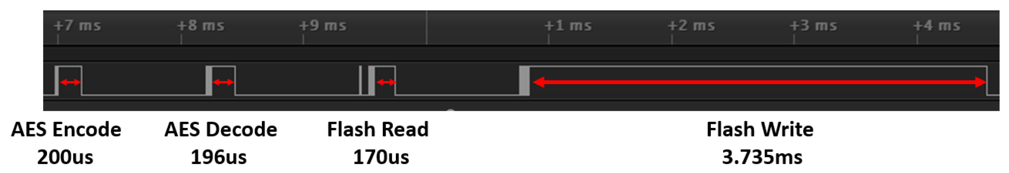
| Function | Time | Average Current |
|---|---|---|
| AES Encode | 200 μs | 6.5 mA |
| AES Decode | 196 μs | 6.5 mA |
| Flash Read | 170 μs | 6.5 mA |
| Flash Write | 3.735 ms | 25.5 mA |
| LoRa Transmit | varies | 100 mA |
| LoRa Receive | varies | 10 mA |
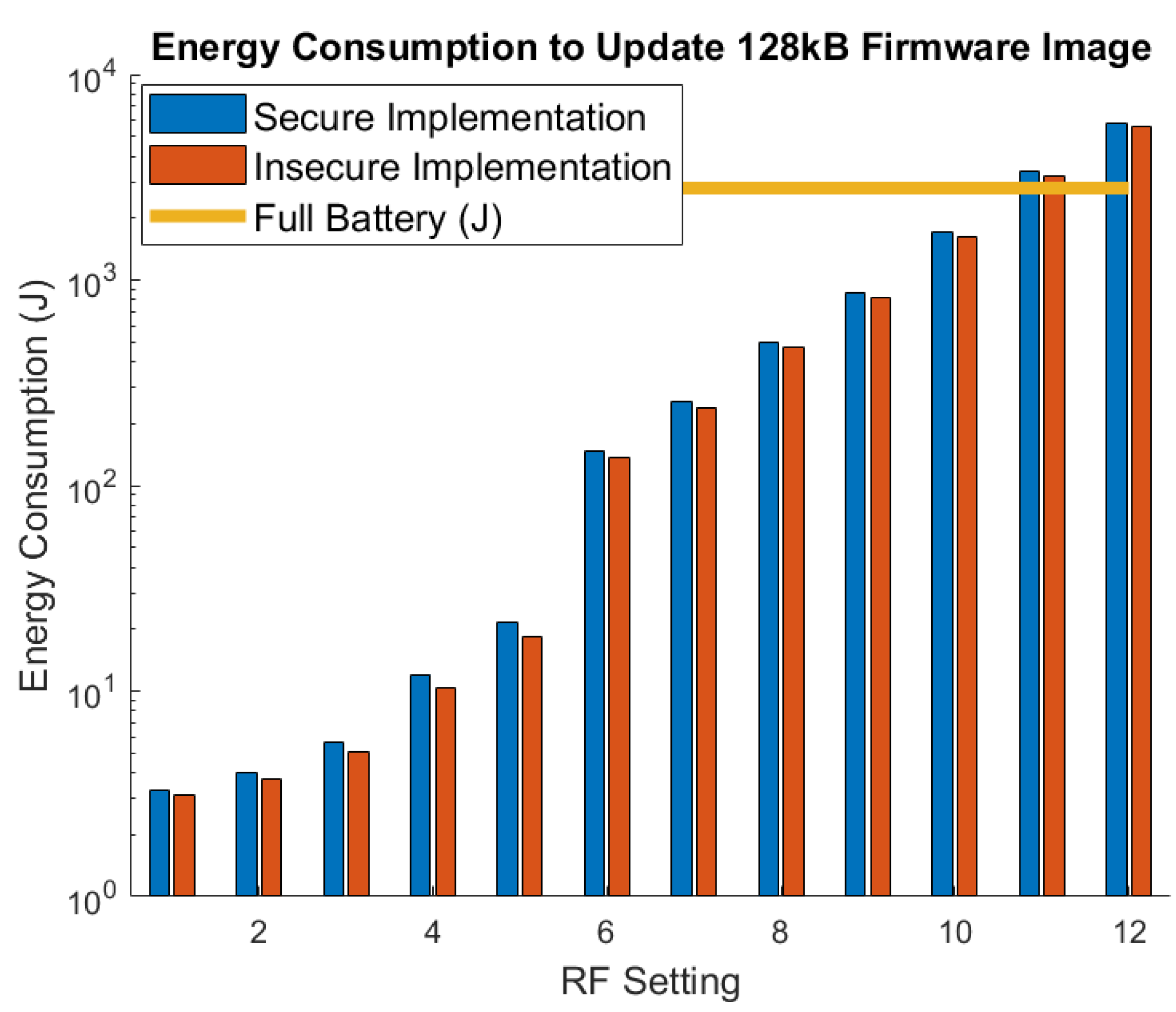
| Setting | Start OCV | Stop OCV | Measured Energy | Expected Energy |
|---|---|---|---|---|
| 7 | 4.19 V | 4.09 V | 266.63 J | 200.2 J |
| 8 | 4.09 V | 92.3 V | 430.7 J | 389 J |
| 9 | 4.18 V | 3.96 V | 709.06 J | 684.5 J |
| 10 | 4.18 V | 3.82 V | 1166.14 J | 1350 J |
| 11 | 4.17 V | 3.29 V | 2669.2 J | 2664 J |
| Objective | Method | Mitigation |
|---|---|---|
| Get Firmware | Observe firmware update by capturing it over RF. | The update is encrypted so it is meaningless to the observer after it is collected. |
| Get Firmware | Falsely claim to be a cattle that needs a firmware update. | The attacker would not have so it would fail the initial authentication. |
| Get Firmware | Read the firmware from the external memory chip. | The image is still encrypted external to the chip so it would not reveal any useful information. |
| Change Firmware | Falsely claim to be the base station and update the firmware on a sensor. | The malicious actor could not compose a valid MAC to pass the initial exchange. |
| Change Firmware | Wait until after the initial exchange and begin adding new firmware to the device. | Each data packet is signed using so no un-authenticated packets would ever be accepted. |
Publisher’s Note: MDPI stays neutral with regard to jurisdictional claims in published maps and institutional affiliations. |
© 2021 by the authors. Licensee MDPI, Basel, Switzerland. This article is an open access article distributed under the terms and conditions of the Creative Commons Attribution (CC BY) license (http://creativecommons.org/licenses/by/4.0/).
Share and Cite
Heeger, D.; Garigan, M.; Eleni Tsiropoulou, E.; Plusquellic, J. Secure LoRa Firmware Update with Adaptive Data Rate Techniques. Sensors 2021, 21, 2384. https://doi.org/10.3390/s21072384
Heeger D, Garigan M, Eleni Tsiropoulou E, Plusquellic J. Secure LoRa Firmware Update with Adaptive Data Rate Techniques. Sensors. 2021; 21(7):2384. https://doi.org/10.3390/s21072384
Chicago/Turabian StyleHeeger, Derek, Maeve Garigan, Eirini Eleni Tsiropoulou, and Jim Plusquellic. 2021. "Secure LoRa Firmware Update with Adaptive Data Rate Techniques" Sensors 21, no. 7: 2384. https://doi.org/10.3390/s21072384
APA StyleHeeger, D., Garigan, M., Eleni Tsiropoulou, E., & Plusquellic, J. (2021). Secure LoRa Firmware Update with Adaptive Data Rate Techniques. Sensors, 21(7), 2384. https://doi.org/10.3390/s21072384