
Underground Parking Lot Navigation System Using Long-Term Evolution Signal


Abstract
1. Introduction
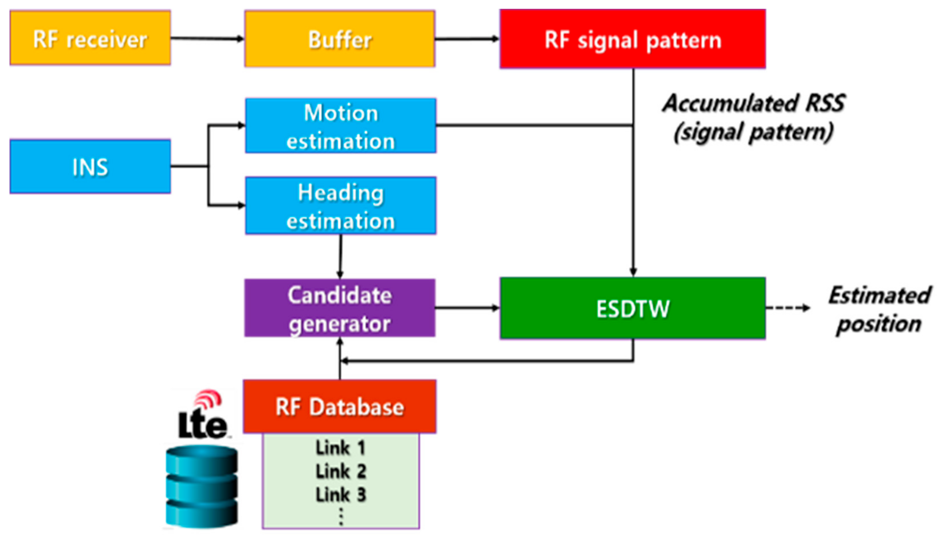
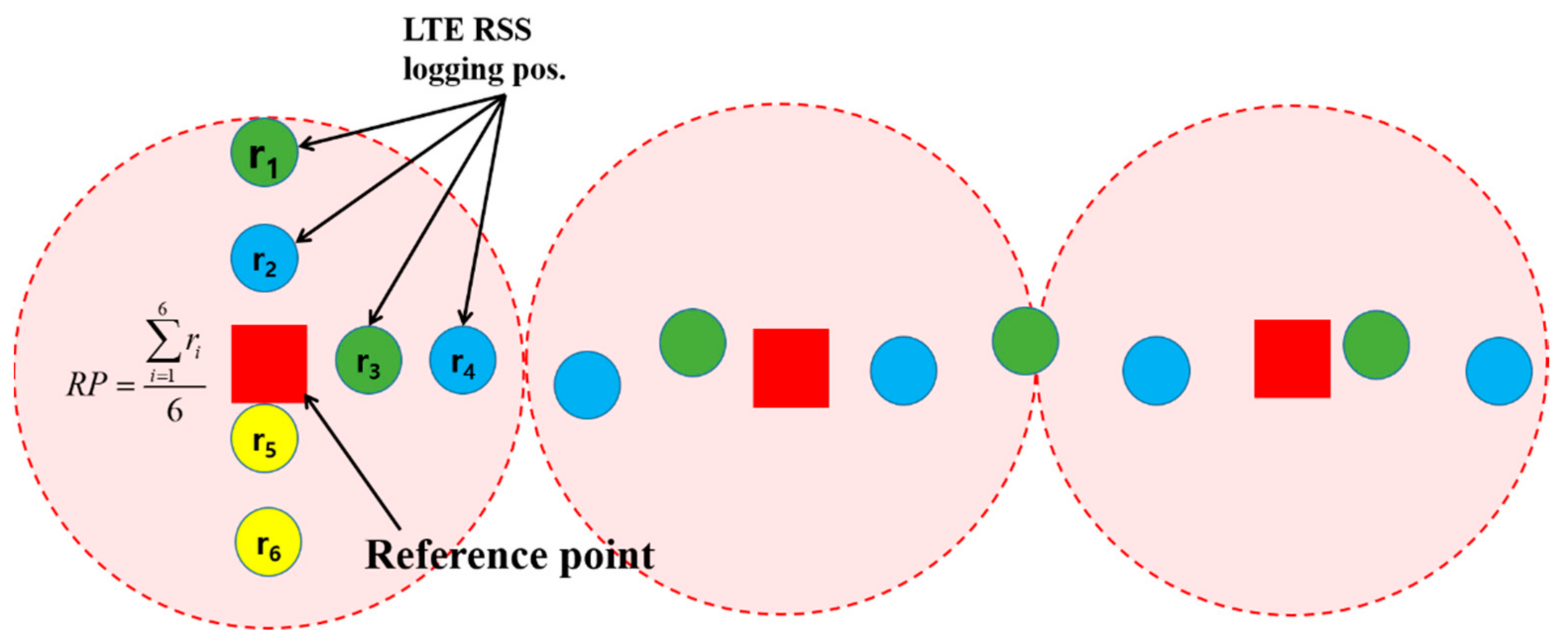
- The accurate position in an underground parking lot is estimated using the accumulation pattern of the LTE RSS. In particular, ESDTW is proposed to compare the LTE sequence and DB, and the effectiveness of the proposed technology is verified experimentally.
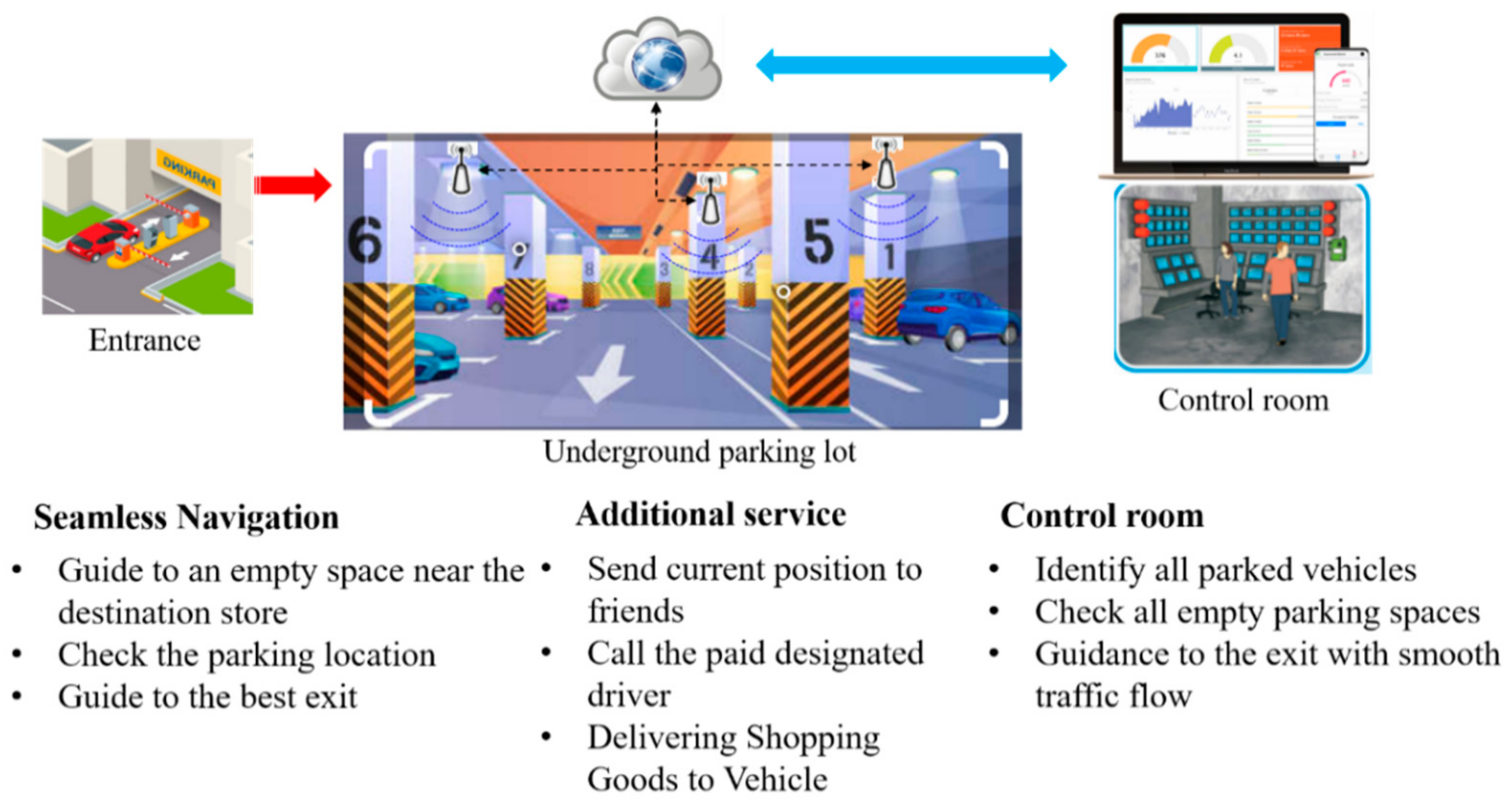
- The proposed system can estimate the position with sufficient accuracy for providing navigation services in an underground parking lot using only a mobile phone, without requiring additional infrastructure. This technology is easy to use, and it is possible to integrate it with the existing vehicle navigation system based on GNSS.
2. Block Diagram of the Proposed System and Its Applications
3. Proposed Method
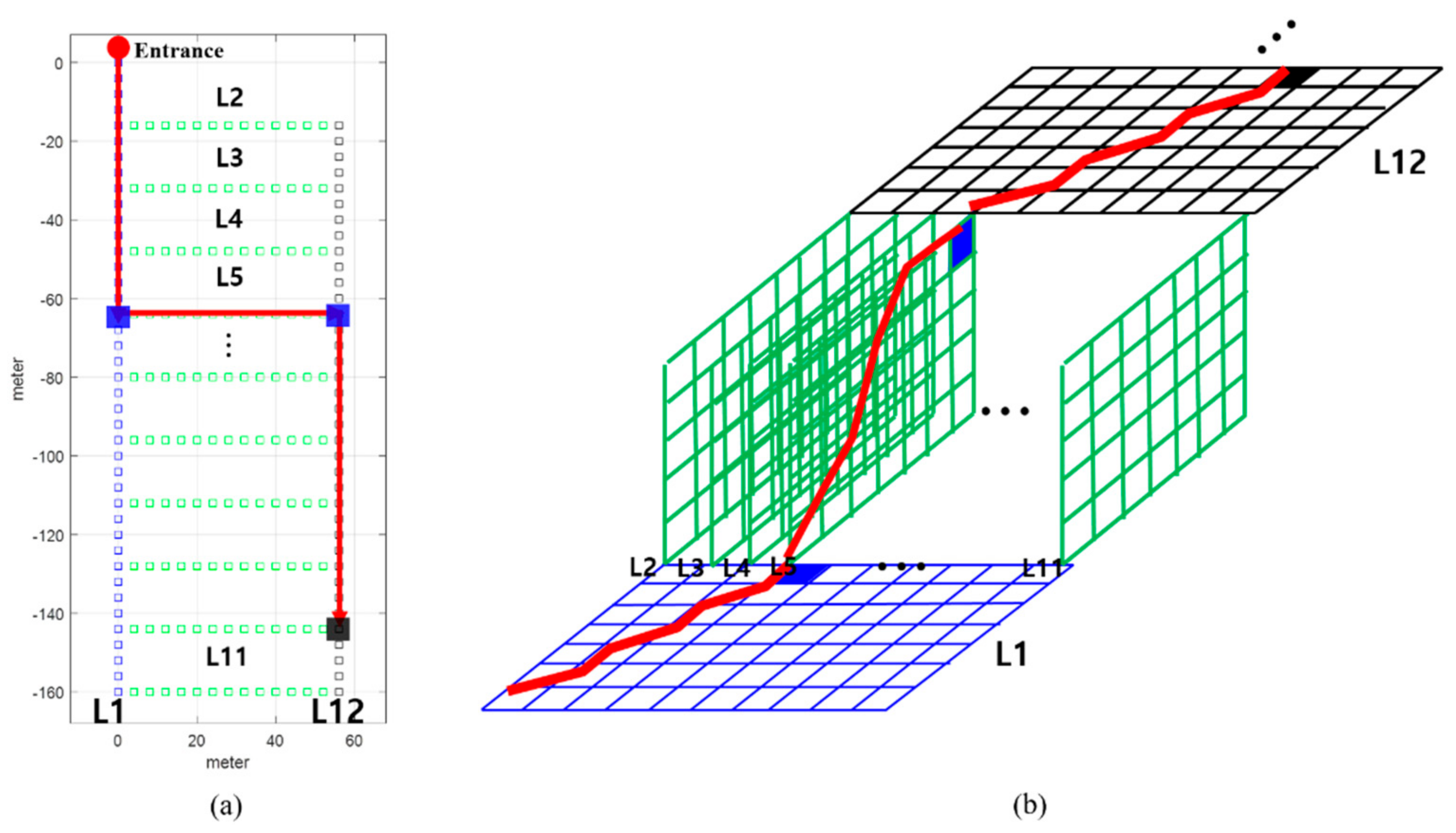
3.1. LTE DB Construction
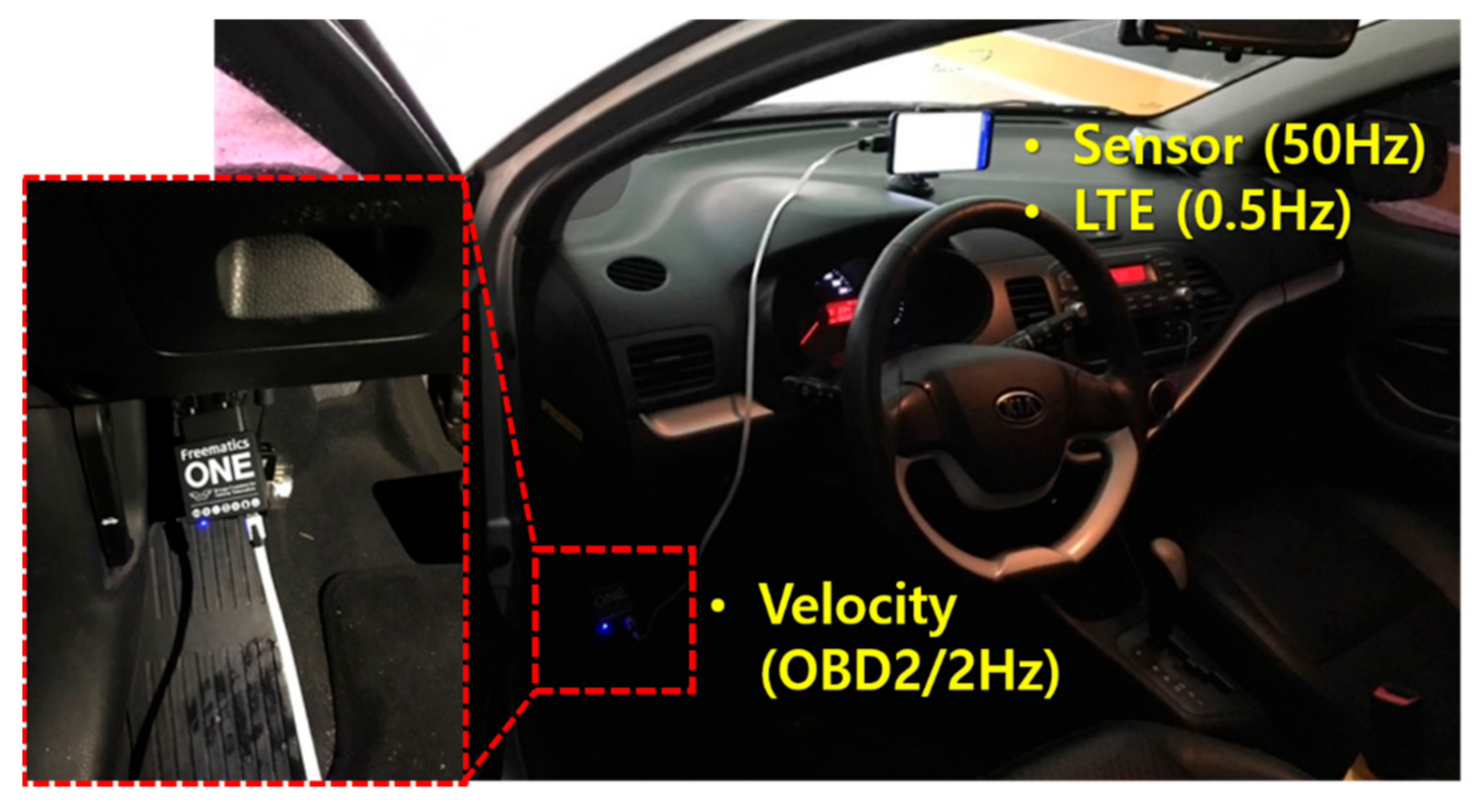
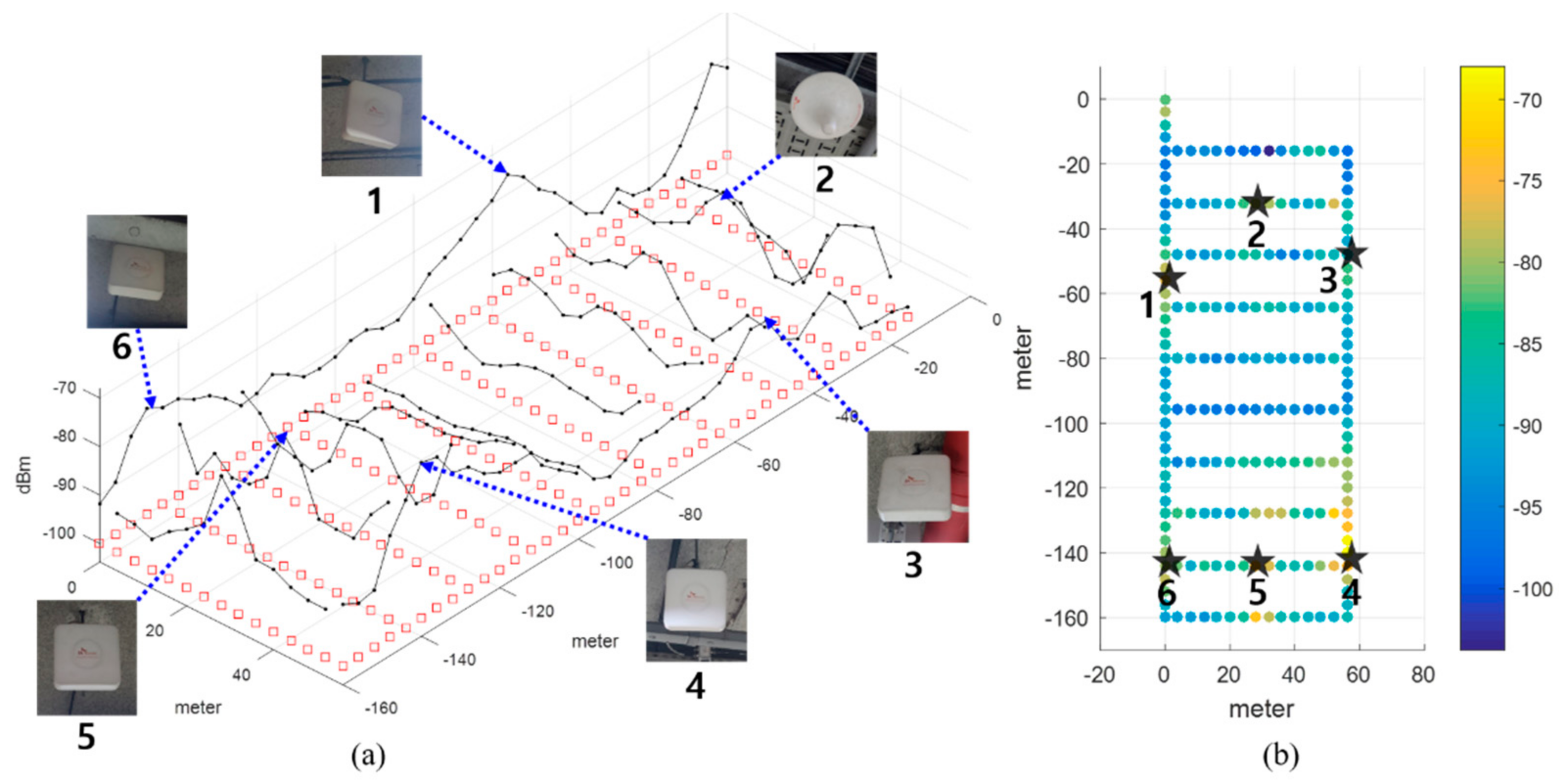
Testbed
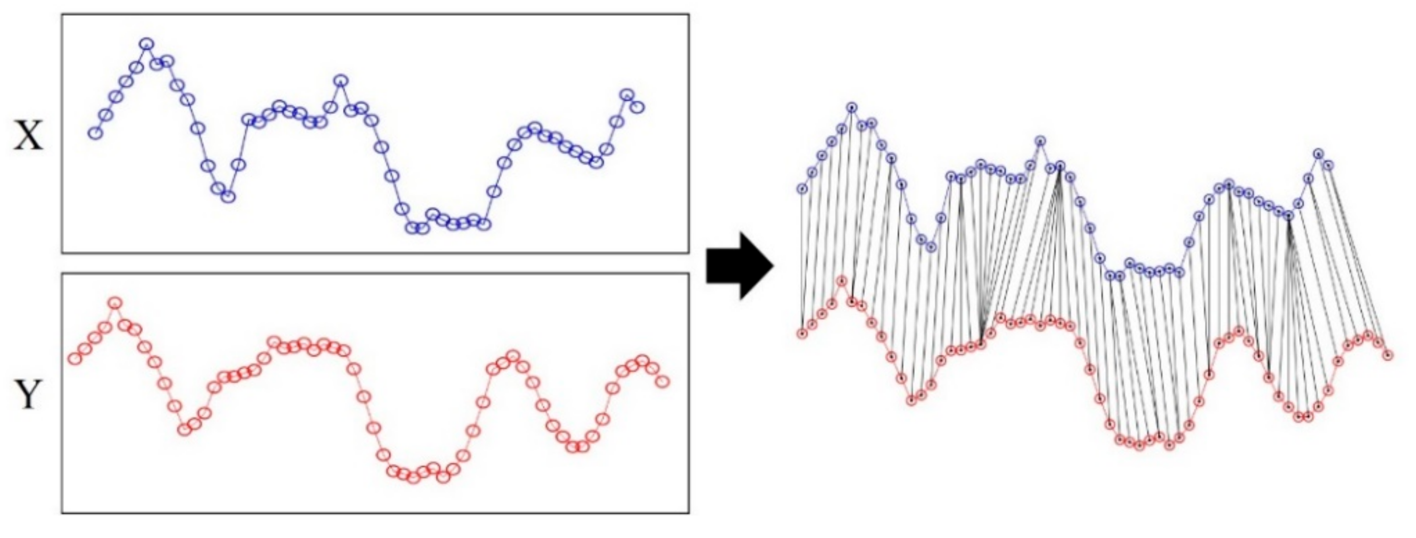
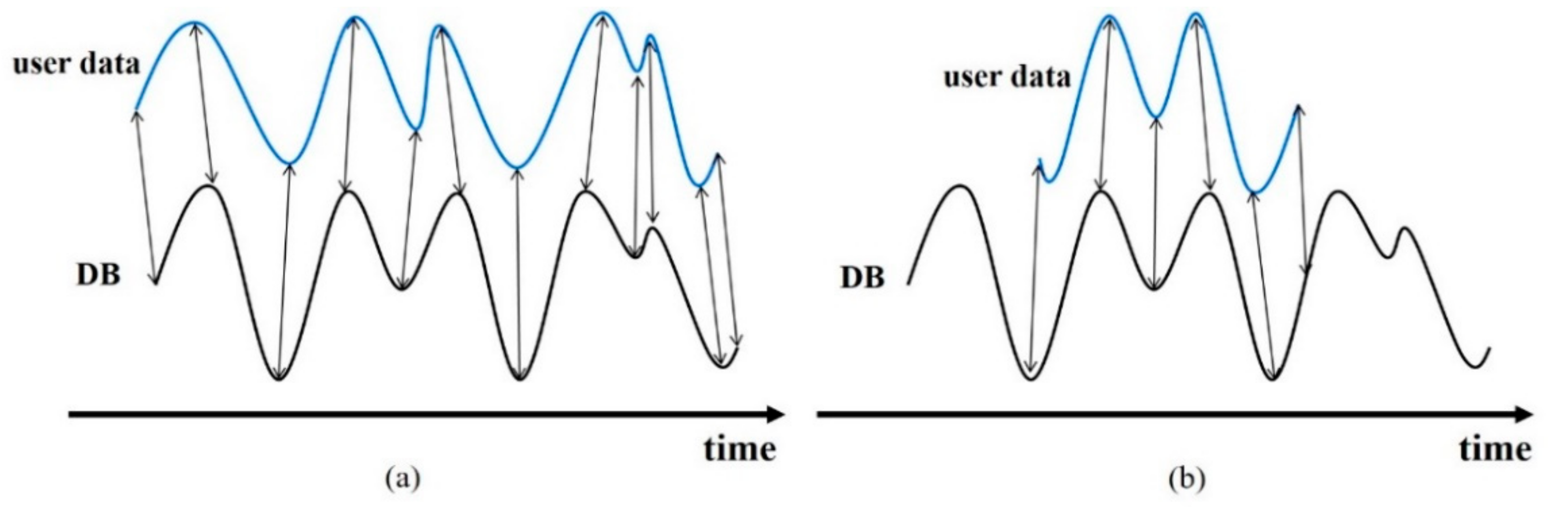
3.2. DTW
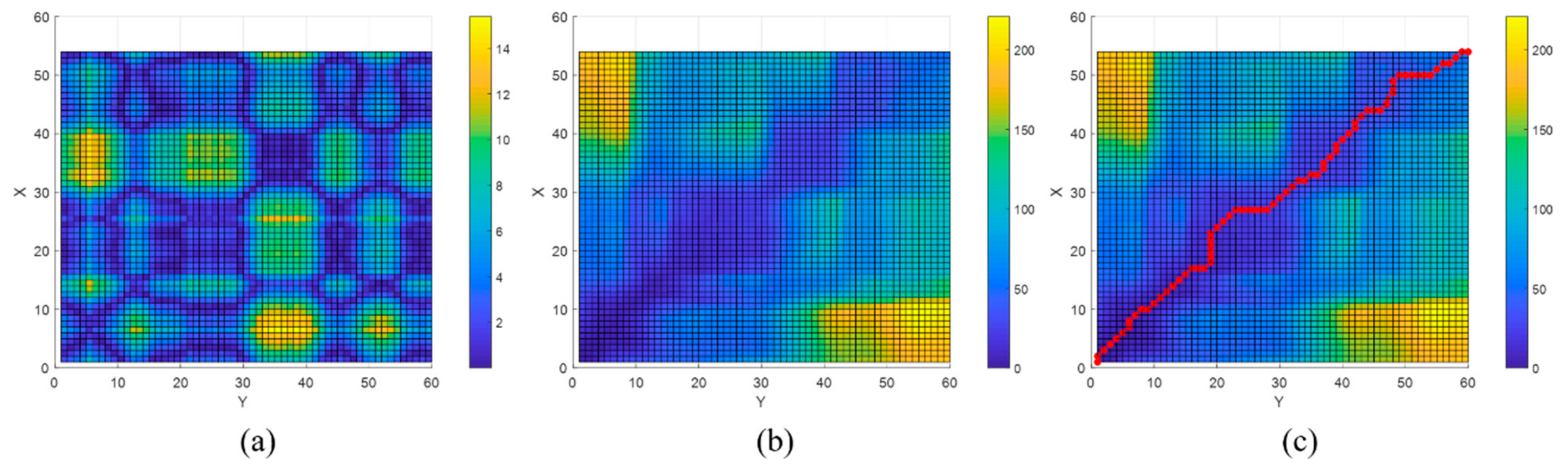
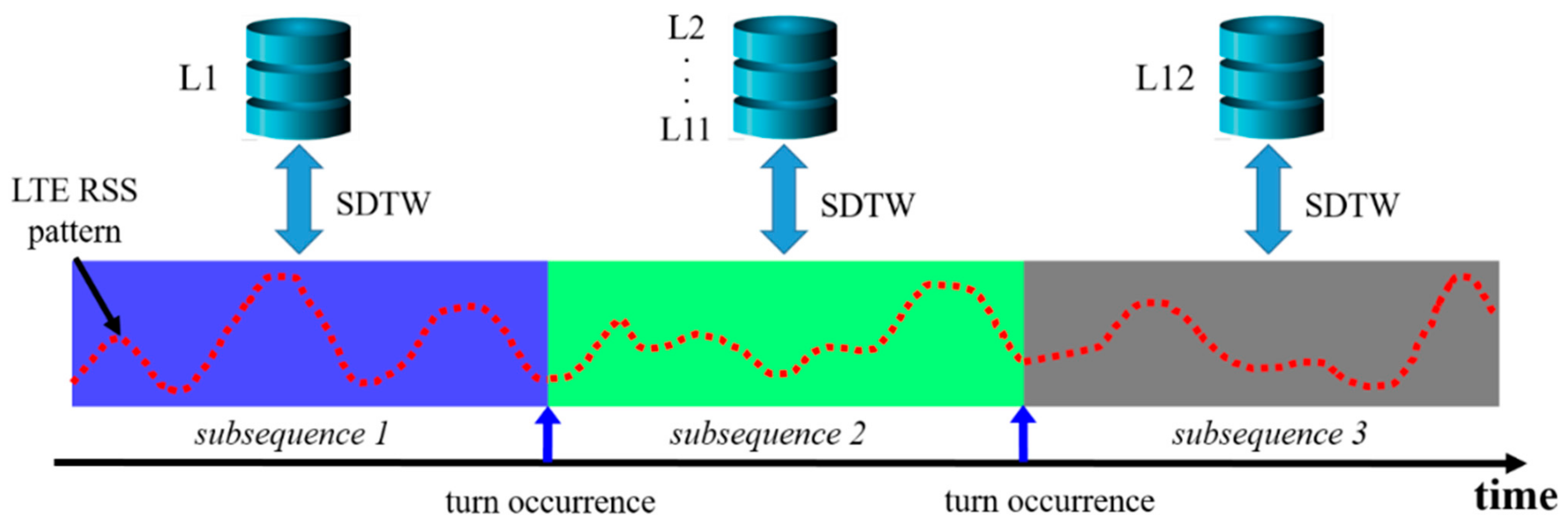
3.3. Proposed Extended Subsequence DTW
4. Experimental Results
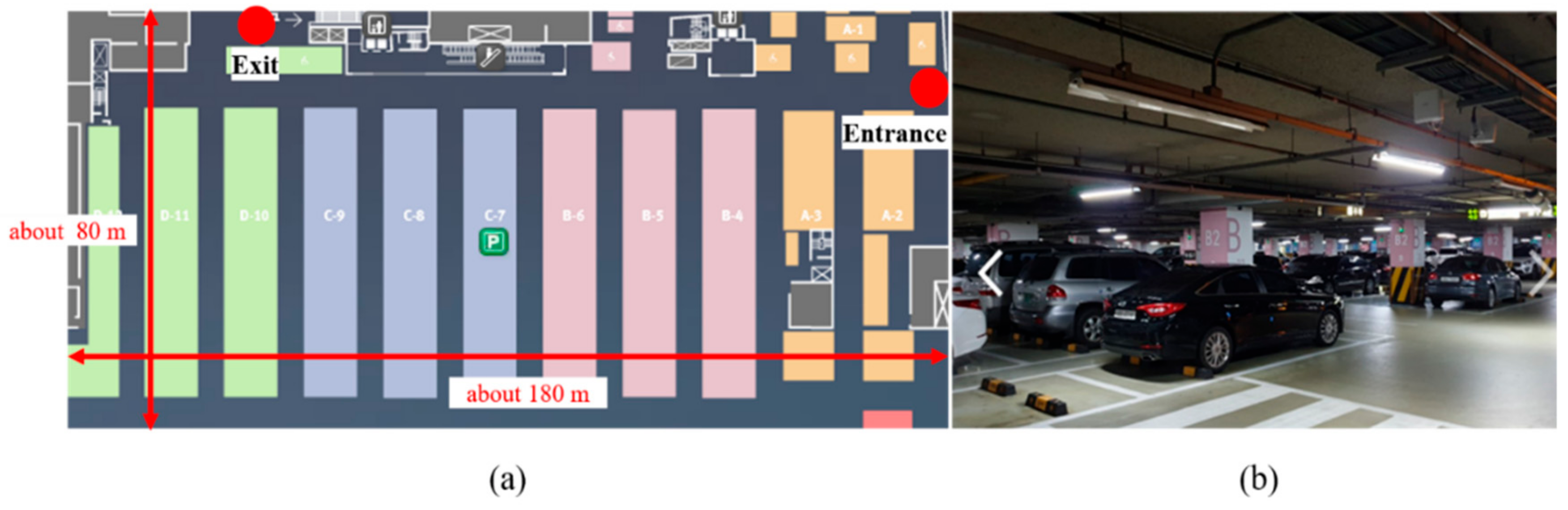
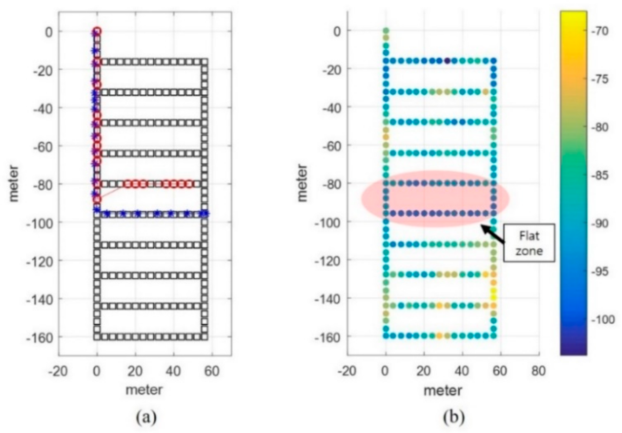
4.1. Testbed and Experimental Setup
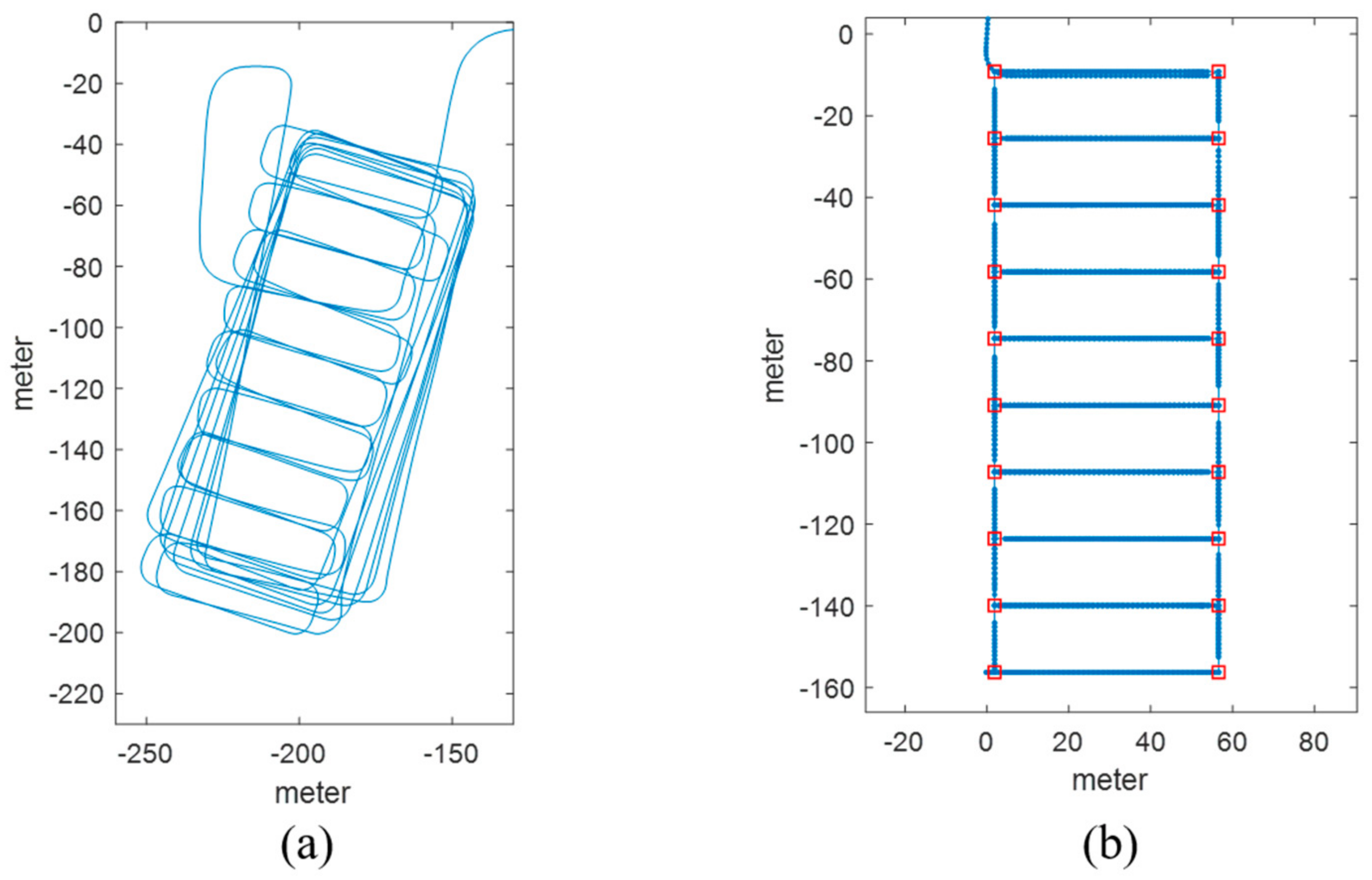
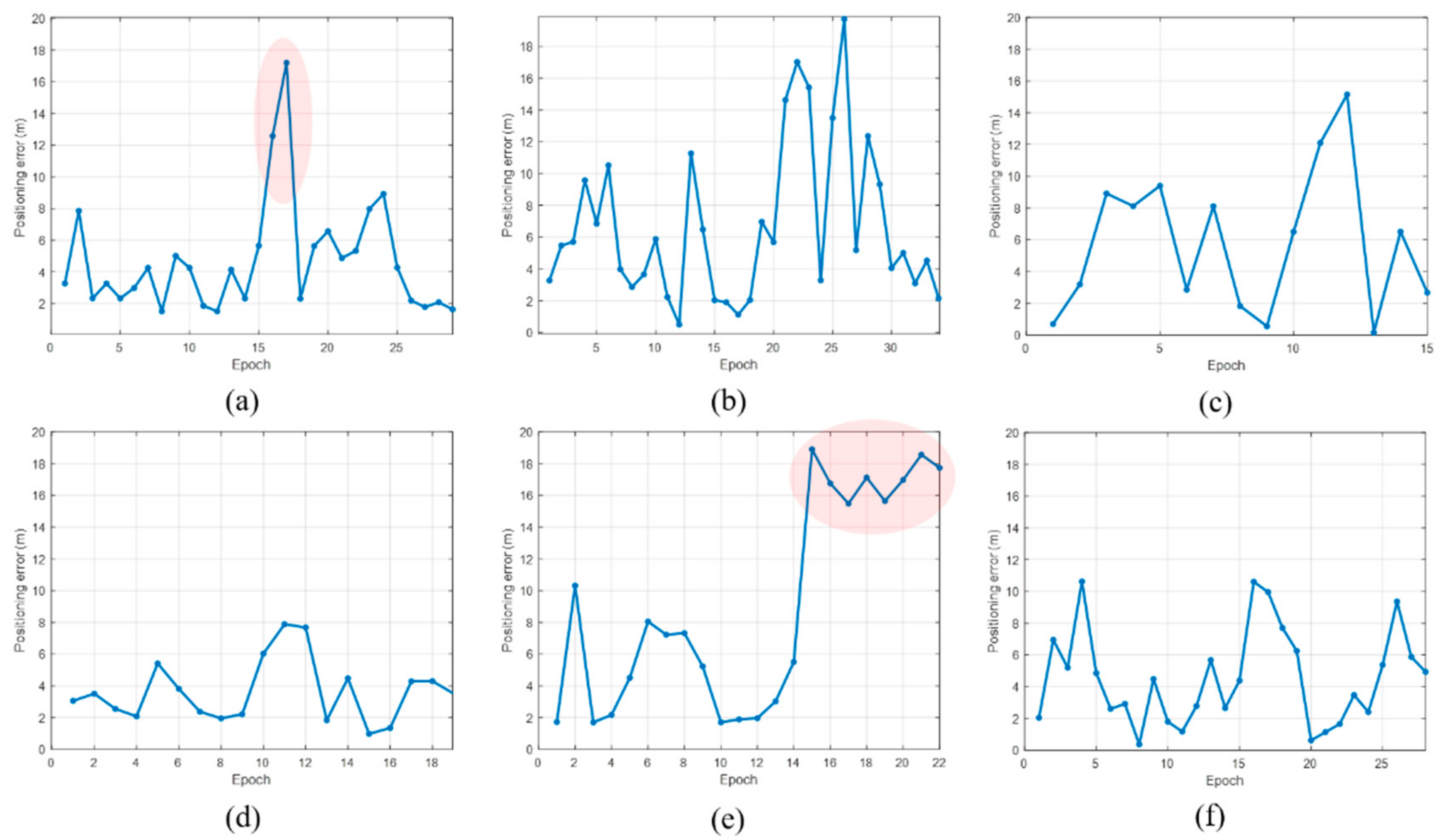
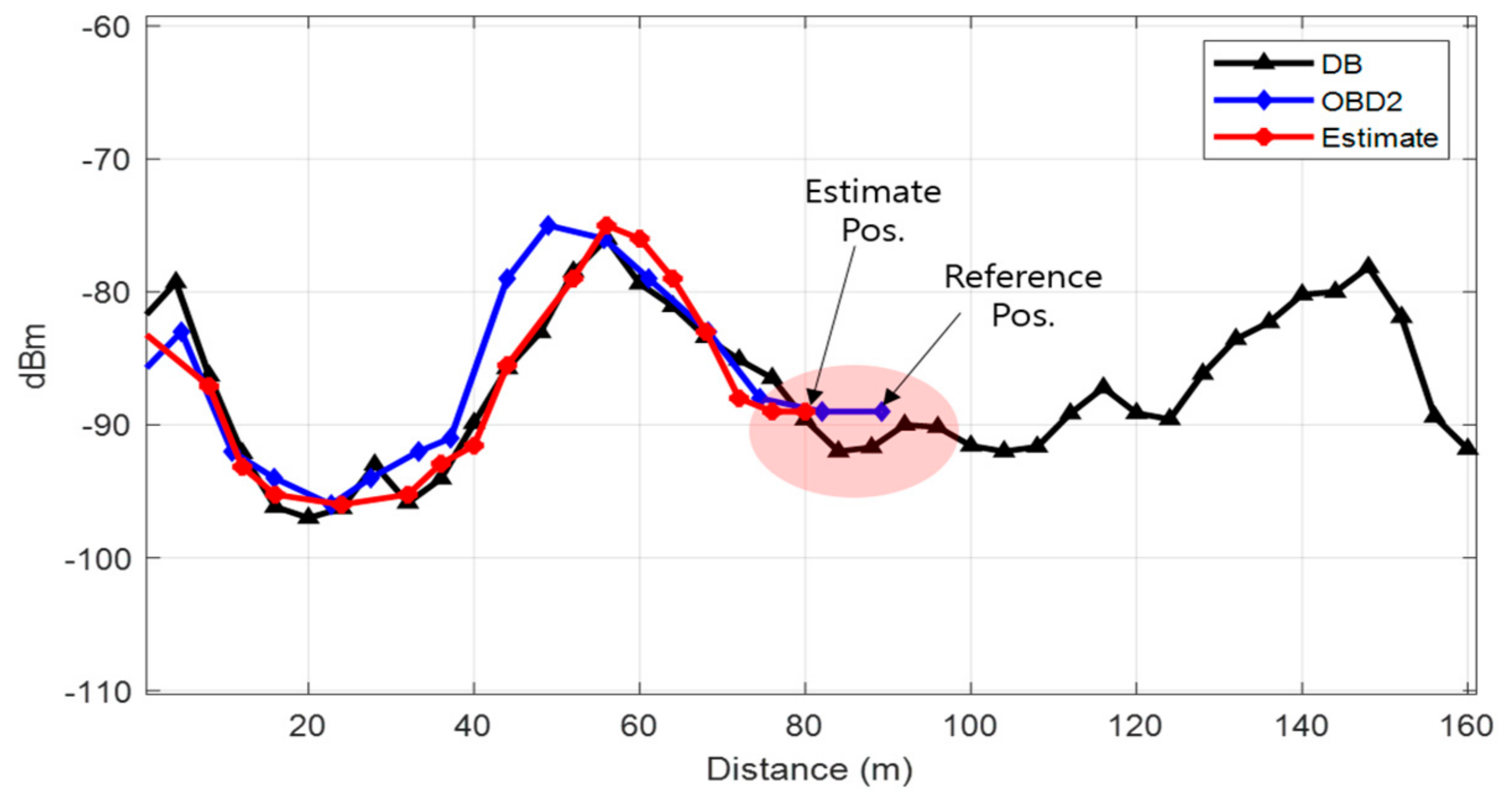
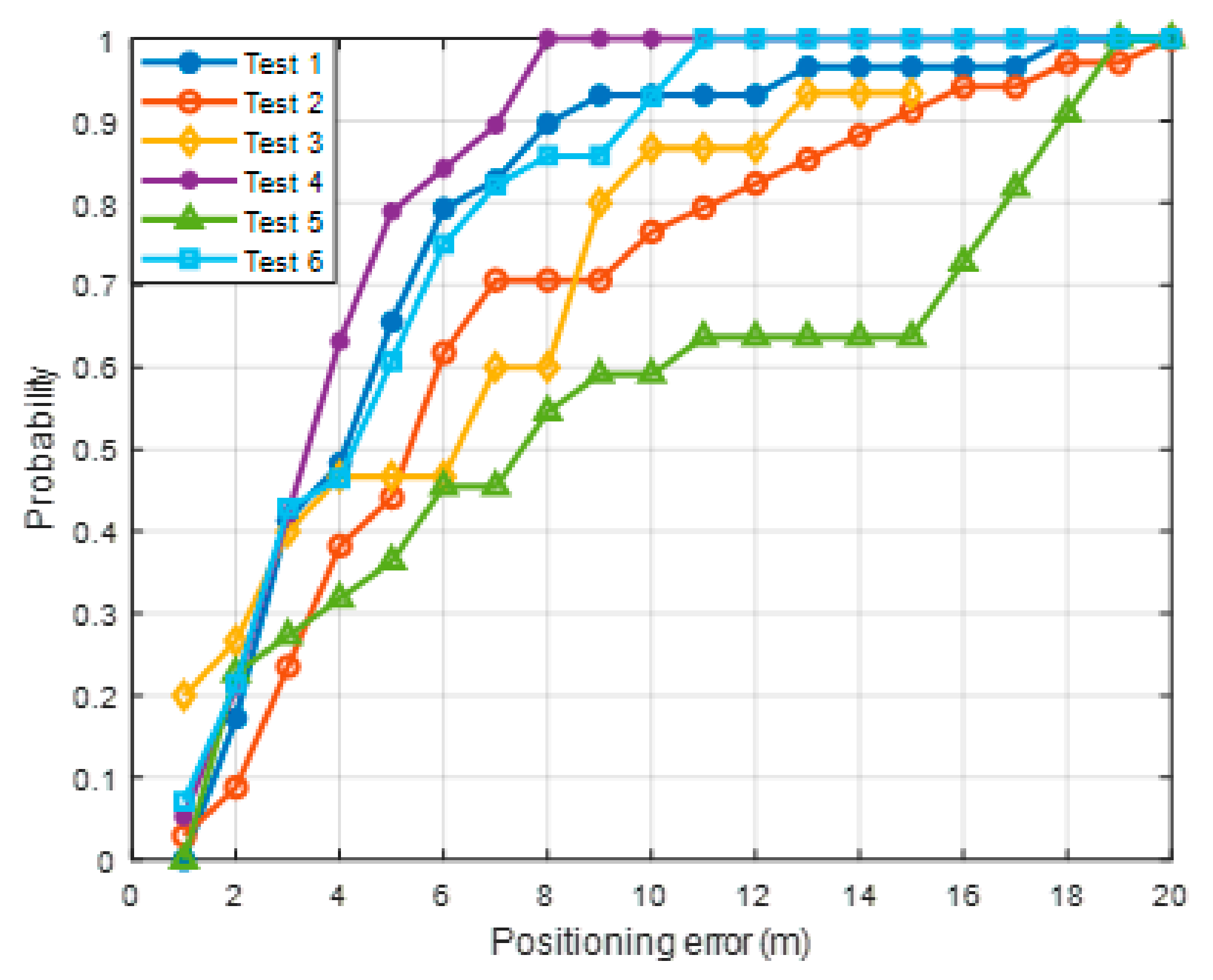
4.2. Result Analysis
4.3. Discussion
5. Conclusions
Author Contributions
Funding
Institutional Review Board Statement
Informed Consent Statement
Data Availability Statement
Conflicts of Interest
References
- Ye, H.; Jing, X.; Liu, L.; Hao, S.; Yu, B. Analysis of the Multiplexing Method of New System Navigation Signals of GPS III First Star L1 Frequency in China’s Regional. Sensors 2019, 19, 5360. [Google Scholar] [CrossRef] [PubMed]
- Kim, C.; So, H.; Lee, T.; Kee, C. A Pseudolite-Based Positioning System for Legacy GNSS Receivers. Sensors 2014, 14, 6104–6123. [Google Scholar] [CrossRef] [PubMed]
- Xu, R.; Chen, W.; Xu, Y.; Ji, S. A new indoor positioning system architecture using gps signals. Sensors 2015, 15, 10074–10087. [Google Scholar] [CrossRef] [PubMed]
- Liu, F.; Wang, J.; Zhang, J.; Han, H. An indoor localization method for pedestrians base on combined UWB/PDR/floor map. Sensors 2019, 19, 2578. [Google Scholar] [CrossRef] [PubMed]
- Alletto, S.; Cucchiara, R.; Del Fiore, G.; Mainetti, L.; Mighali, V.; Patrono, L.; Serra, G. An Indoor Location-Aware System for. IEEEE Internet Things 2016, 3, 244–253. [Google Scholar] [CrossRef]
- Spachos, P.; Plataniotis, K.N. BLE beacons for indoor positioning at an interactive IoT-based smart museum. IEEE Syst. J. 2020, 14, 3483–3493. [Google Scholar] [CrossRef]
- Yadav, R.K.; Bhattarai, B.; Gang, H.S.; Pyun, J.Y. Trusted K nearest Bayesian estimation for indoor positioning system. IEEE Access 2019, 7, 51484–51498. [Google Scholar] [CrossRef]
- Giuliano, R.; Cardarilli, G.C.; Cesarini, C.; Di Nunzio, L.; Fallucchi, F.; Fazzolari, R.; Mazzenga, F.; Re, M.; Vizzarri, A. Indoor localization system based on bluetooth low energy for museum applications. Electronics 2020, 9, 1055. [Google Scholar] [CrossRef]
- Qiu, X.; Wang, B.; Wang, J.; Shen, Y. AOA-based BLE localization with carrier frequency offset mitigation. In Proceedings of the 2020 IEEE International Conference on Communications Workshops (ICC Workshops), Dublin, Ireland, 7–11 June 2020; pp. 2–6. [Google Scholar]
- Monfared, S.; Nguyen, T.H.; Petrillo, L.; De Doncker, P.; Horlin, F. Experimental Demonstration of BLE Transmitter Positioning Based on AOA Estimation. In Proceedings of the 2018 IEEE 29th Annual International Symposium on Personal, Indoor and Mobile Radio Communications (PIMRC), Bologna, Italy, 9–12 September 2018; pp. 856–859. [Google Scholar]
- Wu, T.; Liu, J.; Li, Z.; Liu, K.; Xu, B. Accurate smartphone indoor visual positioning based on a high-precision 3D photorealistic map. Sensors 2018, 18, 1974. [Google Scholar] [CrossRef] [PubMed]
- Hassan, N.U.; Naeem, A.; Pasha, M.A.; Jadoon, T.; Yuen, C. Indoor positioning using visible LED lights: A survey. ACM Comput. Surv. 2015, 48, 1–32. [Google Scholar] [CrossRef]
- Shin, B.; Kim, C.; Kim, J.; Lee, S.; Kee, C.; Kim, H.S.; Lee, T. Motion Recognition-Based 3D Pedestrian Navigation System Using Smartphone. IEEE Sens. J. 2016, 16, 6977–6989. [Google Scholar] [CrossRef]
- Kang, W.; Han, Y. SmartPDR: Smartphone-based pedestrian dead reckoning for indoor localization. IEEE Sens. J. 2015, 15, 2906–2916. [Google Scholar] [CrossRef]
- Shin, S.H.; Lee, M.S.; Park, C.G.; Hong, H.S. Pedestrian dead reckoning system with phone location awareness algorithm. In Proceedings of the IEEE/ION Position, Location and Navigation Symposium, Indian Wells, CA, USA, 4–6 May 2010; pp. 97–101. [Google Scholar]
- Shin, B.; Lee, J.H.; Lee, H.; Kim, E.; Kim, J.; Lee, S.; Cho, Y.S.; Park, S.; Lee, T. Indoor 3D pedestrian tracking algorithm based on PDR using smarthphone. Int. Conf. Control. Autom. Syst. 2012, 1442–1445. [Google Scholar]
- Molina, B.; Olivares, E.; Palau, C.E.; Esteve, M. A multimodal fingerprint-based indoor positioning system for airports. IEEE Access 2018, 6, 10092–10106. [Google Scholar] [CrossRef]
- Shin, B.; Lee, J.H.; Lee, T.; Kim, H.S. Enhanced weighted K-nearest neighbor algorithm for indoor Wi-Fi positioning systems. In Proceedings of the 2012 8th International Conference on Computing Technology and Information Management (NCM and ICNIT), Seoul, Korea, 24–26 April 2012; pp. 574–577. [Google Scholar]
- Ma, R.; Guo, Q.; Hu, C.; Xue, J. An improved WiFi indoor positioning algorithm by weighted fusion. Sensors 2015, 15, 21824–21843. [Google Scholar] [CrossRef] [PubMed]
- Li, N.; Gao, Y.; Wang, Y.; Liu, Z.; Guan, L.; Liu, X. A low-cost underground garage navigation switching algorithm based on kalman filtering. Sensors 2019, 19, 1861. [Google Scholar] [CrossRef] [PubMed]
- Zhao, Z.; Wang, J.; Zhao, X.; Peng, C.; Guo, Q.; Wu, B. NaviLight: Indoor localization and navigation under arbitrary lights. In Proceedings of the IEEE INFOCOM 2017—IEEE Conference on Computer Communications, Atlanta, GA, USA, 1–4 May 2017; pp. 1–9. [Google Scholar]
- Jia, Y.; Jin, Z.; Zhang, H.; Li, Y.; Wang, X.; Shen, L. Indoor navigation for a complex parking building based on computer vision. In Proceedings of the 2019 5th International Conference on Transportation Information and Safety (ICTIS), Liverpool, UK, 14–17 July 2019; pp. 183–190. [Google Scholar]
- Hirakata, Y.; Nakamura, A.; Ohno, K.; Itami, M. Navigation system using ZigBee wireless sensor network for parking. In Proceedings of the 2012 12th International Conference on ITS Telecommunications, Taipei, Taiwan, 5–8 November 2012; pp. 605–609. [Google Scholar]
- Lee, J.H.; Shin, B.; Shin, D.; Park, J.; Ryu, Y.S.; Woo, D.H. Surface Correlation-Based Fingerprinting Method Using LTE Signal for Localization in Urban Canyon. Sensors 2019, 19, 3325. [Google Scholar] [CrossRef]
- Zhang, P.; Zhao, Q.; Li, Y.; Niu, X.; Zhuang, Y.; Liu, J. Collaborative WiFi fingerprinting using sensor-based navigation on smartphones. Sensors 2015, 15, 17534–17557. [Google Scholar] [CrossRef] [PubMed]
- Anguera, X.; Ferrarons, M. Memory efficient subsequence DTW for Query-by-Example Spoken Term Detection. In Proceedings of the 2013 IEEE International Conference on Multimedia and Expo (ICME), San Jose, CA, USA, 15–19 July 2013; pp. 2–7. [Google Scholar]


| Test Num. | Mean (m) | RMSE (m) | Max (m) | CEP (m) |
|---|---|---|---|---|
| 1 | 4.68 | 5.87 | 17.19 | 4.13 |
| 2 | 6.68 | 8.32 | 19.73 | 5.32 |
| 3 | 5.78 | 7.35 | 15.14 | 6.50 |
| 4 | 3.64 | 4.15 | 7.87 | 3.50 |
| 5 | 9.06 | 11.26 | 18.89 | 7.27 |
| 6 | 4.56 | 5.47 | 10.62 | 4.43 |
Publisher’s Note: MDPI stays neutral with regard to jurisdictional claims in published maps and institutional affiliations. |
© 2021 by the authors. Licensee MDPI, Basel, Switzerland. This article is an open access article distributed under the terms and conditions of the Creative Commons Attribution (CC BY) license (http://creativecommons.org/licenses/by/4.0/).
Share and Cite
Shin, B.; Lee, J.H.; Yu, C.; Kim, C.; Lee, T. Underground Parking Lot Navigation System Using Long-Term Evolution Signal. Sensors 2021, 21, 1725. https://doi.org/10.3390/s21051725
Shin B, Lee JH, Yu C, Kim C, Lee T. Underground Parking Lot Navigation System Using Long-Term Evolution Signal. Sensors. 2021; 21(5):1725. https://doi.org/10.3390/s21051725
Chicago/Turabian StyleShin, Beomju, Jung Ho Lee, Changsu Yu, Chulki Kim, and Taikjin Lee. 2021. "Underground Parking Lot Navigation System Using Long-Term Evolution Signal" Sensors 21, no. 5: 1725. https://doi.org/10.3390/s21051725
APA StyleShin, B., Lee, J. H., Yu, C., Kim, C., & Lee, T. (2021). Underground Parking Lot Navigation System Using Long-Term Evolution Signal. Sensors, 21(5), 1725. https://doi.org/10.3390/s21051725