
Bio-Impedance Measurement Optimization for High-Resolution Carotid Pulse Sensing

 ,
,  , and
, and
Abstract
1. Introduction
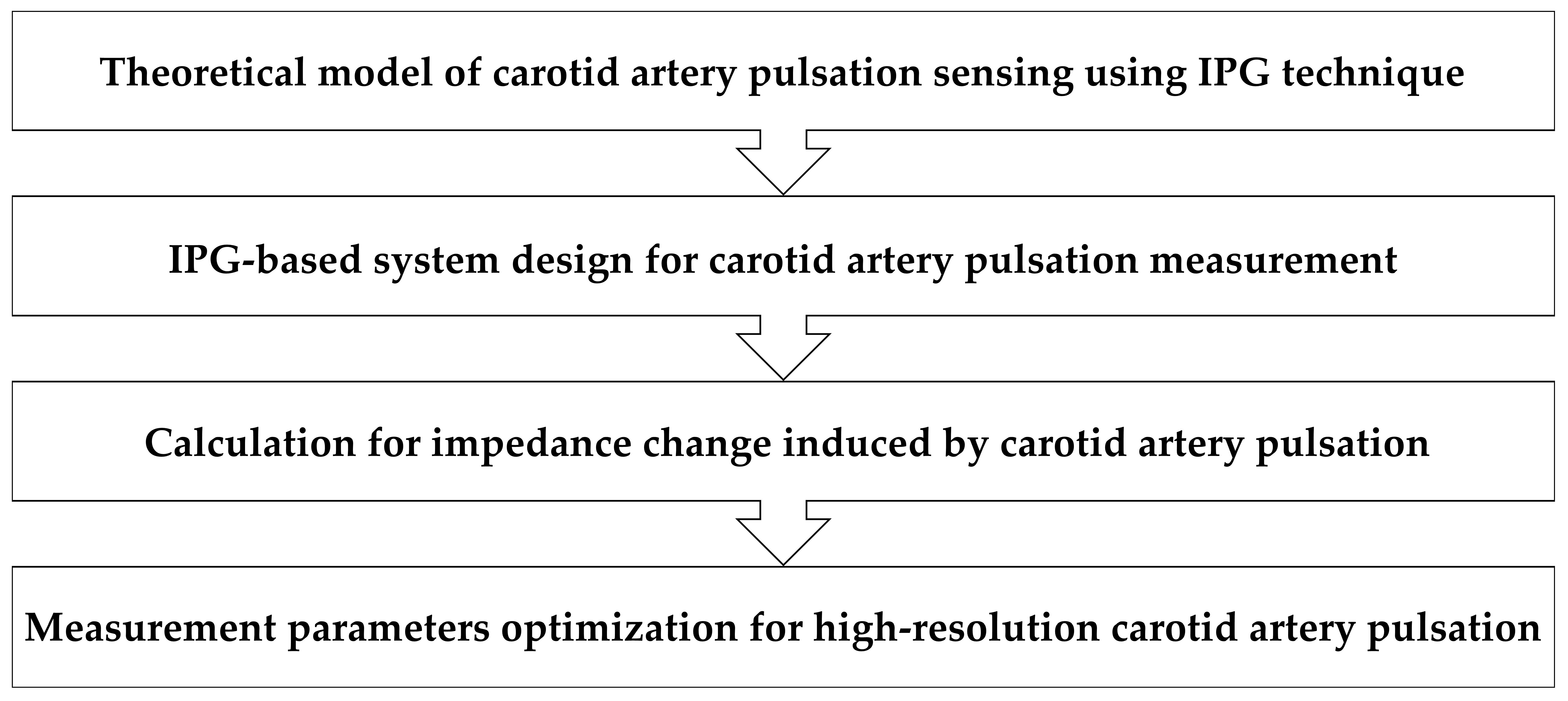
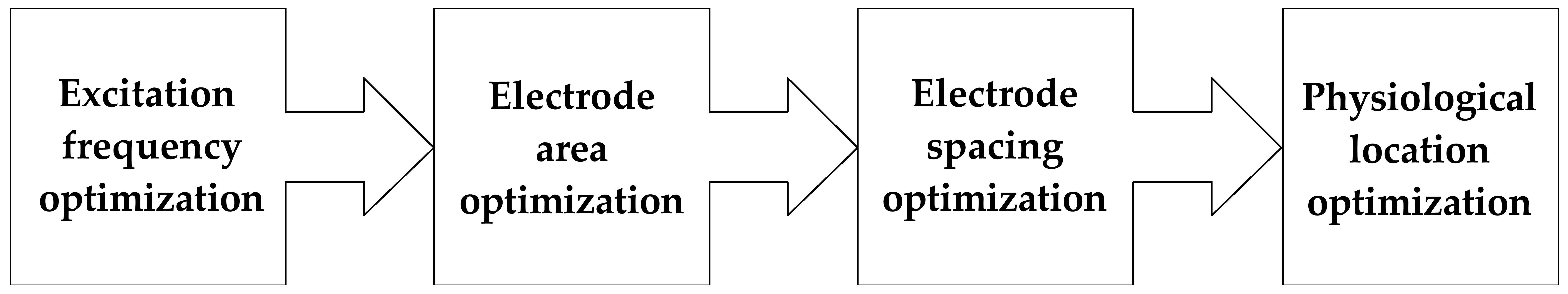
2. Methods
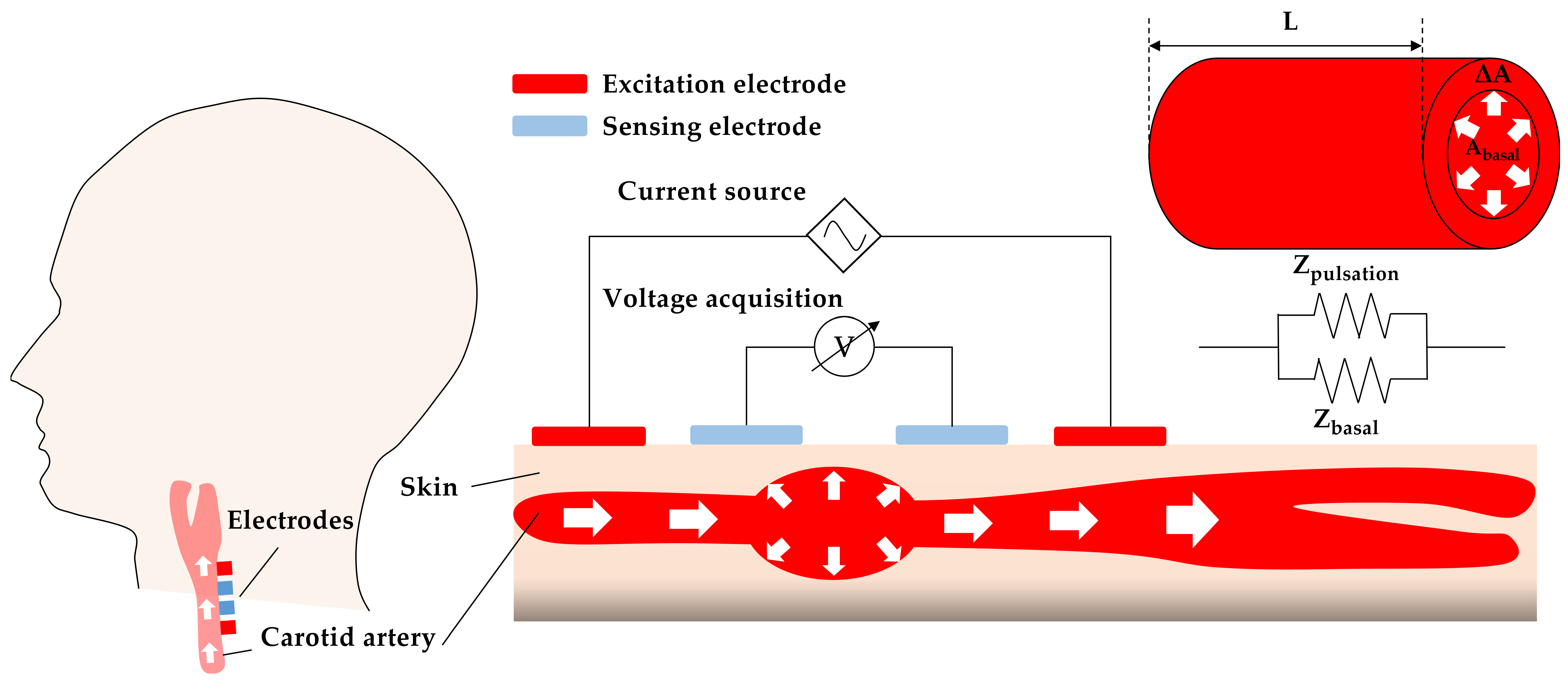
2.1. Theoretical Model of IPG-Based Carotid Artery Pulse Sensing
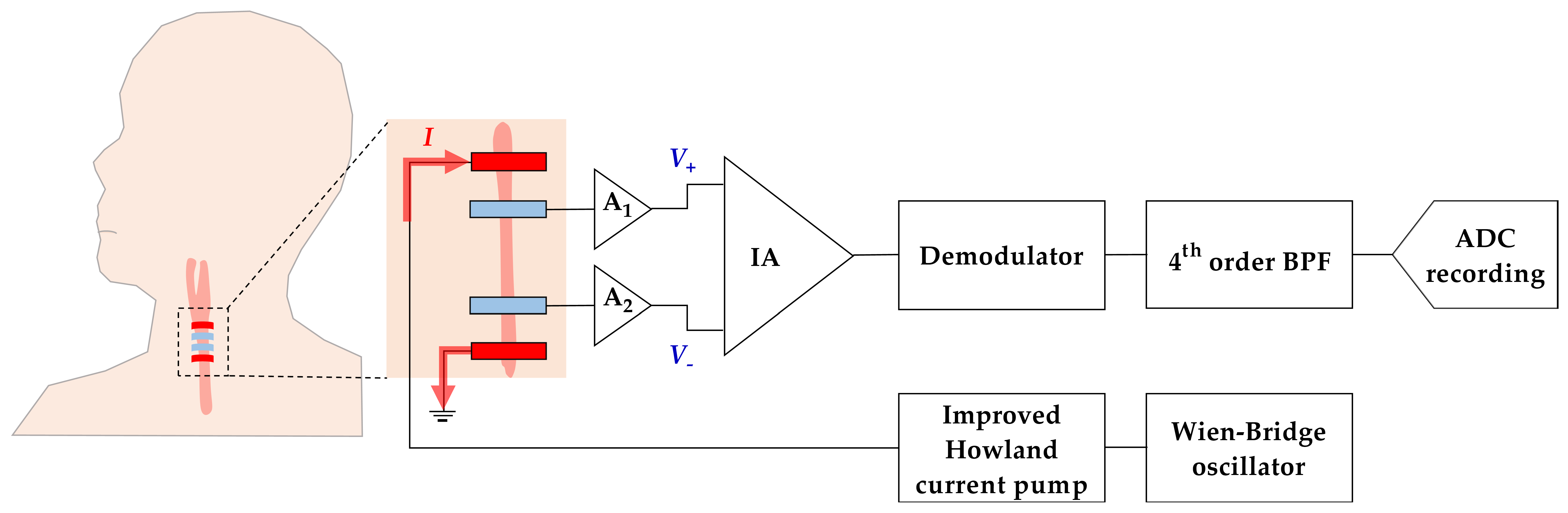
2.2. IPG-Based System Design for Carotid Pulse Measurement
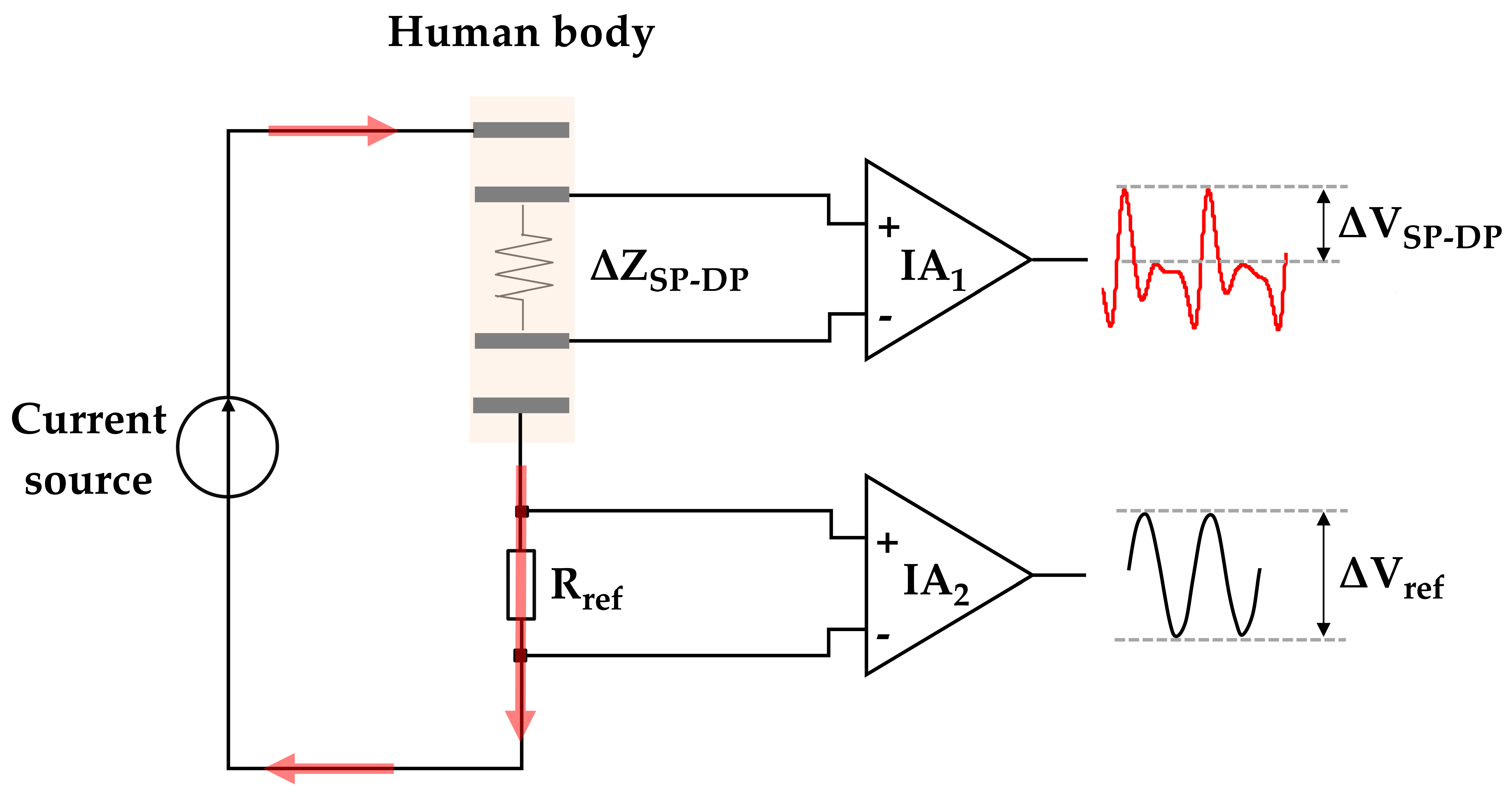
2.3. Calculation for Arterial Impedance Change
2.4. Ethics Statement and Experimental Design
3. Experimental Results
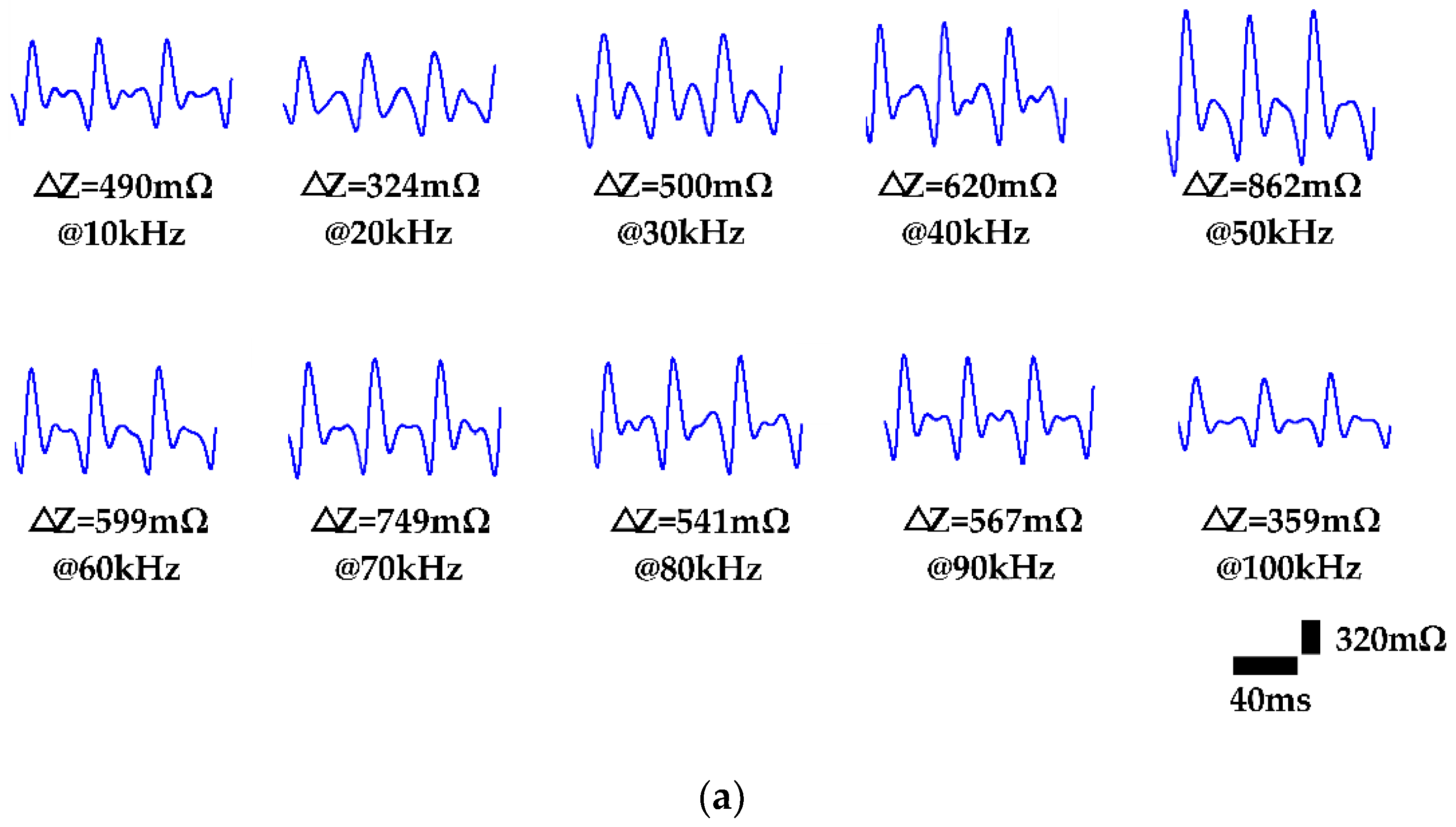
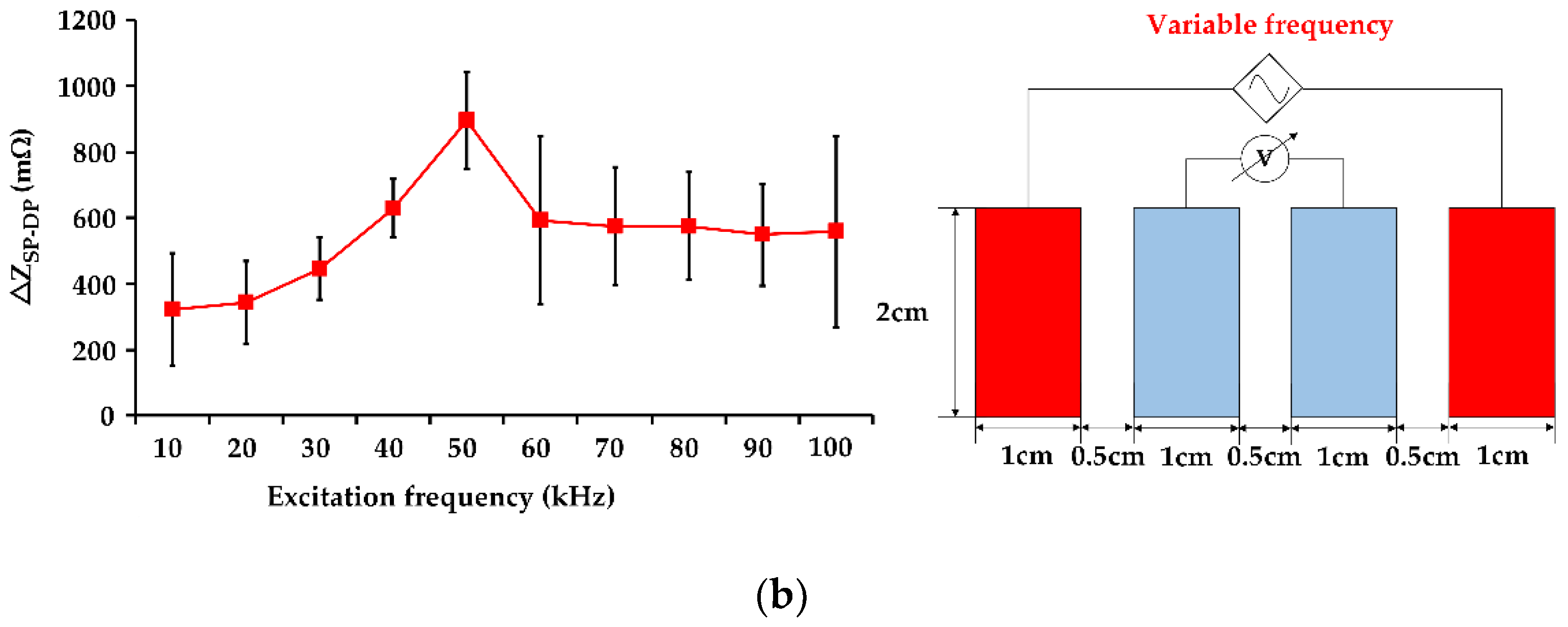
3.1. Influence of Excitation Frequency on IPG Measurement Resolution
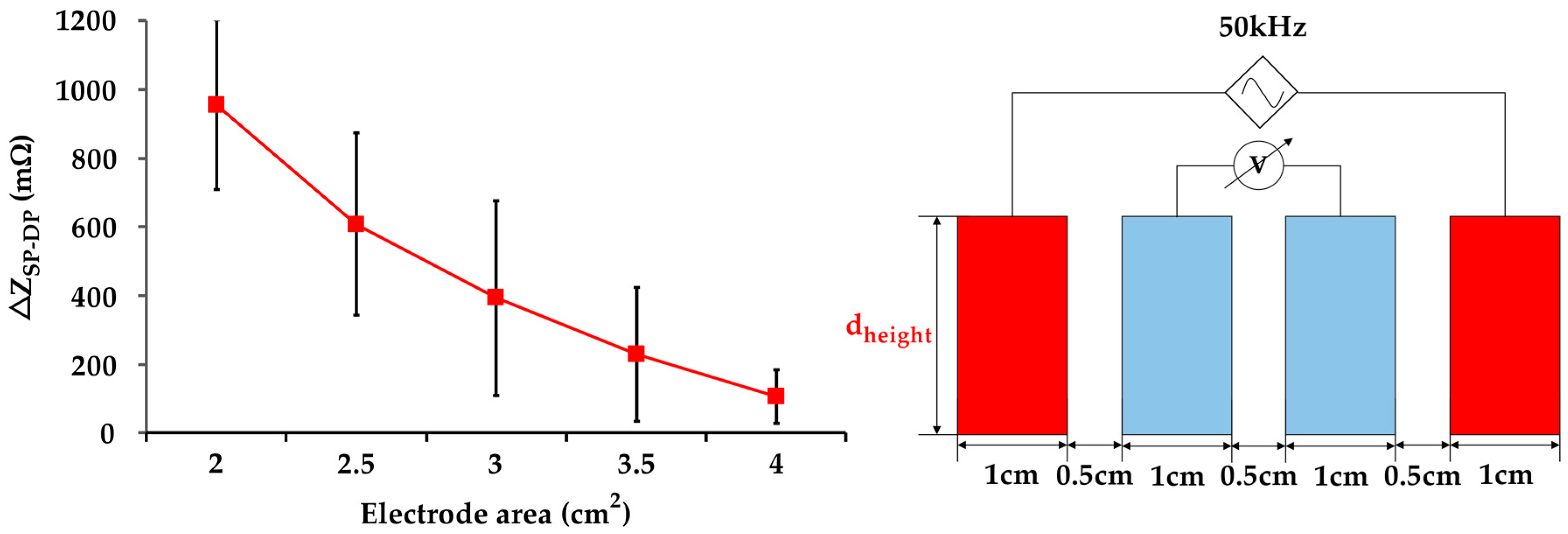
3.2. Influence of Electrode Area on IPG Measurement Resolution
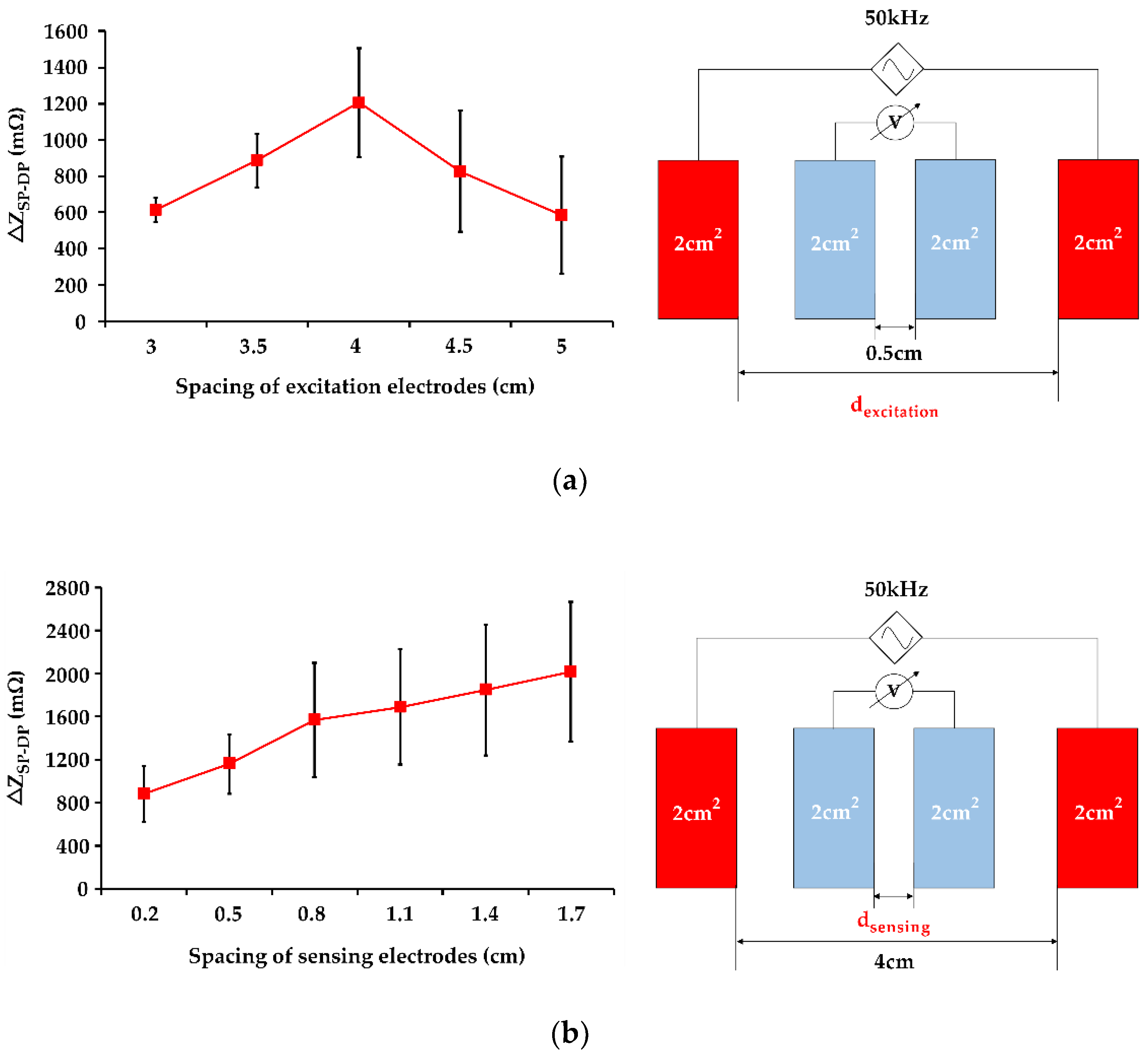
3.3. Influence of Electrode Spacing on IPG Measurement Resolution
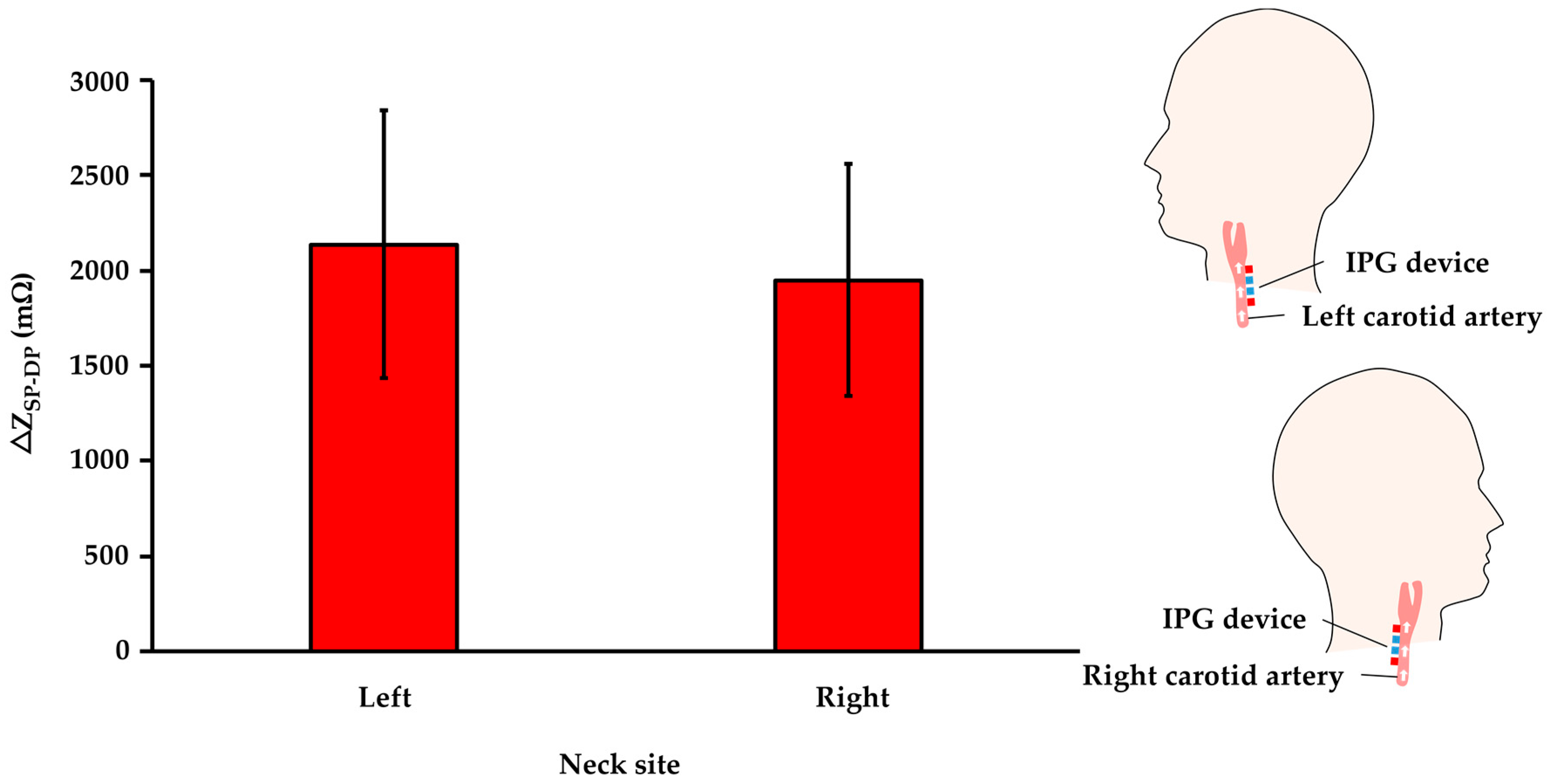
3.4. Influence of Left and Right Side Carotid Artery on IPG Measurement Resolution
4. Discussions
4.1. Significance in IPG-Base Carotid Pulse Sensing
4.2. Influence of Measurement Parameters on IPG Measurement Resolution
4.3. Comparison with Related IPG Studies
4.4. Limitations
5. Conclusions
Author Contributions
Funding
Institutional Review Board Statement
Informed Consent Statement
Data Availability Statement
Conflicts of Interest
References
- Maarman, G.J.; Chakafana, G.; Sliwa, K. World Heart Day: A World Heart Federation Communiqué on the Future of Basic Sciences and Translational Medicine in Global Cardiovascular Research; American Physiological Society: Bethesda, MD, USA, 2020. [Google Scholar]
- Kitterman, J.A.; Phibbs, R.H.; Tooley, W.H. Catheterization of umbilical vessels in newborn infants. Pediatr. Clin. N. Am. 1970, 17, 895–912. [Google Scholar] [CrossRef]
- McEniery, C.M.; Cockcroft, J.R.; Roman, M.J.; Franklin, S.S.; Wilkinson, I.B. Central blood pressure: Current evidence and clinical importance. Eur. Heart J. 2014, 35, 1719–1725. [Google Scholar] [CrossRef]
- Dias, D.; Paulo Silva Cunha, J. Wearable Health Devices-Vital Sign Monitoring, Systems and Technologies. Sensors 2018, 18, 2414. [Google Scholar] [CrossRef]
- Ding, X.R.; Zhao, N.; Yang, G.Z.; Pettigrew, R.I.; Lo, B.; Miao, F.; Li, Y.; Liu, J.; Zhang, Y.T. Continuous Blood Pressure Measurement From Invasive to Unobtrusive: Celebration of 200th Birth Anniversary of Carl Ludwig. IEEE J. Biomed. Health Inform. 2016, 20, 1455–1465. [Google Scholar] [CrossRef]
- Zheng, Y.L.; Ding, X.R.; Poon, C.C.; Lo, B.P.; Zhang, H.; Zhou, X.L.; Yang, G.Z.; Zhao, N.; Zhang, Y.T. Unobtrusive sensing and wearable devices for health informatics. IEEE Trans. Bio-Med. Eng. 2014, 61, 1538–1554. [Google Scholar] [CrossRef] [PubMed]
- Khan, Y.; Han, D.; Ting, J.; Ahmed, M.; Nagisetty, R.; Arias, A.C. Organic Multi-Channel Optoelectronic Sensors for Wearable Health Monitoring. IEEE Access 2019, 7, 128114–128124. [Google Scholar] [CrossRef]
- Lochner, C.M.; Khan, Y.; Pierre, A.; Arias, A.C. All-organic optoelectronic sensor for pulse oximetry. Nat. Commun. 2014, 5, 5745. [Google Scholar] [CrossRef]
- Poh, M.Z.; Poh, Y.C. Validation of a Standalone Smartphone Application for Measuring Heart Rate Using Imaging Photoplethysmography. Telemed. J. e-Health Off. J. Am. Telemed. Assoc. 2017, 23, 678–683. [Google Scholar] [CrossRef]
- Tabei, F.; Gresham, J.M.; Askarian, B.; Jung, K.; Chong, J.W. Cuff-Less Blood Pressure Monitoring System Using Smartphones. IEEE Access 2020, 8, 11534–11545. [Google Scholar] [CrossRef]
- Pesti, K.; Metshein, M.; Annus, P.; Kõiv, H.; Min, M. Electrode Placement Strategies for the Measurement of Radial Artery Bioimpedance: Simulations and Experiments. IEEE Trans. Instrum. Meas. 2020, 70, 1–10. [Google Scholar] [CrossRef]
- Raghunath, M.; Kiran, V.; Aravapalli, S. Design of an Optical Blood Pressure Sensor for Noninvasive Monitoring of Blood Pressure. Int. J. Sci. Eng. Adv. Technol. 2015, 3, 1112–1117. [Google Scholar]
- Yang, X.; Wang, Y.; Qing, X. A Flexible Capacitive Pressure Sensor Based on Ionic Liquid. Sensors 2018, 18, 2395. [Google Scholar] [CrossRef]
- Rao, K.S.; Samyuktha, W.; Vardhan, D.V.; Naidu, B.G.; Kumar, P.A.; Sravani, K.G.; Guha, K. Design and sensitivity analysis of capacitive MEMS pressure sensor for blood pressure measurement. Microsyst. Technol. 2020, 26, 2371–2379. [Google Scholar] [CrossRef]
- Ma, L.; Yu, X.; Yang, Y.; Hu, Y.; Zhang, X.; Li, H.; Ouyang, X.; Zhu, P.; Sun, R.; Wong, C.-P. Highly sensitive flexible capacitive pressure sensor with a broad linear response range and finite element analysis of micro-array electrode. J. Mater. 2020, 6, 321–329. [Google Scholar] [CrossRef]
- Kim, J.; Chou, E.F.; Le, J.; Wong, S.; Chu, M.; Khine, M. Soft Wearable Pressure Sensors for Beat-to-Beat Blood Pressure Monitoring. Adv. Healthc. Mater. 2019, 8, e1900109. [Google Scholar] [CrossRef]
- Liu, Z.D.; Liu, J.K.; Wen, B.; He, Q.Y.; Li, Y.; Miao, F. Cuffless Blood Pressure Estimation Using Pressure Pulse Wave Signals. Sensors 2018, 18, 4227. [Google Scholar] [CrossRef] [PubMed]
- McLaughlin, J.; McNeill, M.; Braun, B.; McCormack, P.D. Piezoelectric sensor determination of arterial pulse wave velocity. Physiol. Meas. 2003, 24, 693–702. [Google Scholar] [CrossRef]
- Wang, T.W.; Lin, S.F. Wearable Piezoelectric-Based System for Continuous Beat-to-Beat Blood Pressure Measurement. Sensors 2020, 20, 851. [Google Scholar] [CrossRef] [PubMed]
- Liu, S.H.; Cheng, D.C.; Su, C.H. A Cuffless Blood Pressure Measurement Based on the Impedance Plethysmography Technique. Sensors 2017, 17, 1176. [Google Scholar] [CrossRef]
- Huynh, T.H.; Jafari, R.; Chung, W.-Y. An Accurate Bioimpedance Measurement System for Blood Pressure Monitoring. Sensors 2018, 18, 95. [Google Scholar] [CrossRef] [PubMed]
- Wang, T.W.; Chen, W.X.; Chu, H.W.; Lin, S.F. Single-channel Bio-impedance Measurement for Wearable Continuous Blood Pressure Monitoring. IEEE Trans. Instrum. Meas. 2020, 1. [Google Scholar] [CrossRef]
- Ibrahim, B.; Jafari, R. Cuffless Blood Pressure Monitoring from an Array of Wrist Bio-Impedance Sensors Using Subject-Specific Regression Models: Proof of Concept. IEEE Trans. Biomed. Circuits Syst. 2019, 13, 1723–1735. [Google Scholar] [CrossRef] [PubMed]
- Weyer, S.; Weber, H.; Kleeberg, C.; Leonhardt, S.; Wartzek, T. Development of a real-time, semi-capacitive impedance phlebography device. J. Electr. Bioimpedance 2015, 6, 2–9. [Google Scholar] [CrossRef]
- Wang, T.W.; Chu, H.W.; Chen, W.X.; Shih, Y.T.; Hsu, P.C.; Cheng, H.M.; Lin, S.F. Single-Channel Impedance Plethysmography Neck Patch Device for Unobtrusive Wearable Cardiovascular Monitoring. IEEE Access 2020, 8, 184909–184919. [Google Scholar] [CrossRef]
- Soleimani, E.; Mokhtari-Dizaji, M.; Fatouraee, N.; Saberi, H. Assessing the blood pressure waveform of the carotid artery using an ultrasound image processing method. Ultrasonography 2017, 36, 144–152. [Google Scholar] [CrossRef] [PubMed]
- Chi, Y.; Jung, T.-P.; Cauwenberghs, G. Dry-Contact and Noncontact Biopotential Electrodes: Methodological Review. Biomed. Eng. IEEE Rev. 2010, 3, 106–119. [Google Scholar] [CrossRef] [PubMed]
- Fu, Y.; Zhao, J.; Dong, Y.; Wang, X. Dry Electrodes for Human Bioelectrical Signal Monitoring. Sensors 2020, 20, 3651. [Google Scholar] [CrossRef]
- Anand, G.; Lowe, A.; Al-Jumaily, A. Simulation of impedance measurements at human forearm within 1 kHz to 2 MHz. J. Electr. Bioimpedance 2016, 7, 20. [Google Scholar] [CrossRef]
- Stahn, A.; Terblanche, E.; Gunga, H.-C. Use of Bioelectrical Impedance: General Principles and Overview. In Handbook of Anthropometry: Physical Measures of Human Form in Health and Disease; Preedy, V.R., Ed.; Springer: New York, NY, USA, 2012; pp. 49–90. [Google Scholar] [CrossRef]
- Naranjo-Hernández, D.; Reina-Tosina, J.; Min, M. Fundamentals, Recent Advances, and Future Challenges in Bioimpedance Devices for Healthcare Applications. J. Sens. 2019, 2019, 9210258. [Google Scholar] [CrossRef]
- Wang, J.-J.; Wei-Chih, H.; Kao, T.; Liu, C.-P.; Lin, S.-K. Development of forearm impedance plethysmography for the minimally invasive monitoring of cardiac pumping function. J. Biomed. Sci. Eng. 2011, 4, 122–129. [Google Scholar] [CrossRef][Green Version]
- Min, M.; Kõiv, H.; Priidel, E.; Pesti, K.; Annus, P. Noninvasive Acquisition of the Aortic Blood Pressure Waveform. In Wearable Devices-The Big Wave of Innovation; IntechOpen: London, UK, 2019. [Google Scholar]
- Brandão, A.A.; Amodeo, C.; Alcântara, C.; Barbosa, E.; Nobre, F.; Pinto, F.; Vilela-Martin, J.F.; Bastos, J.M.; Yugar-Toledo, J.C.; Mota-Gomes, M.A.; et al. I Luso-Brazilian positioning on central arterial pressure. Arquivos brasileiros de cardiologia 2017, 108, 100–108. [Google Scholar] [CrossRef] [PubMed]
- Sanchez, B.; Bandarenka, A.S.; Vandersteen, G.; Schoukens, J.; Bragos, R. Novel approach of processing electrical bioimpedance data using differential impedance analysis. Med. Eng. Phys. 2013, 35, 1349–1357. [Google Scholar] [CrossRef] [PubMed]
- Zhang, F.; Sanchez, B.; Rutkove, S.B.; Yang, Y.; Zhong, H.; Li, J.; Teng, Z. Numerical estimation of Fricke-Morse impedance model parameters using single-frequency sinusoidal excitation. Physiol. Meas. 2019, 40, 09nt01. [Google Scholar] [CrossRef] [PubMed]
- Bera, T.K. Bioelectrical Impedance Methods for Noninvasive Health Monitoring: A Review. J. Med. Eng. 2014, 2014, 381251. [Google Scholar] [CrossRef]
- Hassan, Y.; Eldosoky, M.A.; El-Wakad, M.T.I. The effect of vascular diseases on bioimpedance measurements: Mathematical modeling. Biomed. Res. Ther. 2018, 5, 2414–2431. [Google Scholar]
- Chitturi, V.; Farrukh, N. Spatial resolution in electrical impedance tomography: A topical review. J. Electr. Bioimpedance 2017, 8, 66–78. [Google Scholar] [CrossRef]
- Huynh, T.H.; Jafari, R.; Chung, W.Y. Noninvasive Cuffless Blood Pressure Estimation Using Pulse Transit Time and Impedance Plethysmography. IEEE Trans. Bio-Med. Eng. 2019, 66, 967–976. [Google Scholar] [CrossRef] [PubMed]
- Grimnes, S.; Martinsen, Ø.G. Chapter 6—Geometrical Analysis. In Bioimpedance and Bioelectricity Basics, 3rd ed.; Grimnes, S., Martinsen, Ø.G., Eds.; Academic Press: Oxford, UK, 2015; pp. 141–178. [Google Scholar] [CrossRef]
- Jacob, S. Chapter 7—Head and neck. In Human Anatomy; Jacob, S., Ed.; Churchill Livingstone: London, UK, 2008; pp. 181–225. [Google Scholar] [CrossRef]
- Tahmasebpour, H.R.; Buckley, A.R.; Cooperberg, P.L.; Fix, C.H. Sonographic Examination of the Carotid Arteries. Radiographics 2005, 25, 1561–1575. [Google Scholar] [CrossRef]
- Cho, M.; Kim, J.; Cho, S.H. A bio-impedance measurement system for portable monitoring of heart rate and pulse wave velocity using small body area. In Proceedings of the 2009 IEEE International Symposium on Circuits and Systems (ISCAS), Taipei, Taiwan, 24–27 May 2009; pp. 3106–3109. [Google Scholar]
- Mancia, G.; Ferrari, A.; Gregorini, L.; Parati, G.; Ferrari, M.C.; Pomidossi, G.; Zanchetti, A. Control of blood pressure by carotid sinus baroreceptors in human beings. Am. J. Cardiol. 1979, 44, 895–902. [Google Scholar] [CrossRef]
- Thomas, P.K.; Mathias, C.J. Chapter 52—Diseases of the Ninth, Tenth, Eleventh, and Twelfth Cranial Nerves. In Peripheral Neuropathy, 4th ed.; Dyck, P.J., Thomas, P.K., Eds.; W.B. Saunders: Philadelphia, PA, USA, 2005; pp. 1273–1293. [Google Scholar] [CrossRef]


| Technique | PPG | Pressure Sensor | IPG |
|---|---|---|---|
| Mechanism | light reflection or transmission | mechanical to electrical conversion | electrical impedance measurement |
| Advantage | wearable application | ruggedness | deep region detection |
| Challenge | superficial artery | semi-occlusive measurement | skin-electrode contact in dry electrode |
| Author | Artery | Participants | ΔZmax |
|---|---|---|---|
| Cho et al. [44] | radial artery | 2 healthy subjects | 131.1 mΩ |
| Huynh et al. [21] | radial artery | 15 healthy subjects | 325.8 mΩ |
| Huynh et al. [40] | radial artery | 15 healthy subjects | 67.1 mΩ |
| Wang et al. [22] | radial artery | 30 healthy subjects | 594 mΩ |
| Our work | carotid artery | 6 healthy subjects | 2137 mΩ |
Publisher’s Note: MDPI stays neutral with regard to jurisdictional claims in published maps and institutional affiliations. |
© 2021 by the authors. Licensee MDPI, Basel, Switzerland. This article is an open access article distributed under the terms and conditions of the Creative Commons Attribution (CC BY) license (http://creativecommons.org/licenses/by/4.0/).
Share and Cite
Wang, T.-W.; Chu, H.-W.; Chou, L.; Sung, Y.-L.; Shih, Y.-T.; Hsu, P.-C.; Cheng, H.-M.; Lin, S.-F. Bio-Impedance Measurement Optimization for High-Resolution Carotid Pulse Sensing. Sensors 2021, 21, 1600. https://doi.org/10.3390/s21051600
Wang T-W, Chu H-W, Chou L, Sung Y-L, Shih Y-T, Hsu P-C, Cheng H-M, Lin S-F. Bio-Impedance Measurement Optimization for High-Resolution Carotid Pulse Sensing. Sensors. 2021; 21(5):1600. https://doi.org/10.3390/s21051600
Chicago/Turabian StyleWang, Ting-Wei, Hsiao-Wei Chu, Lin Chou, Yen-Ling Sung, Yuan-Ta Shih, Po-Chun Hsu, Hao-Min Cheng, and Shien-Fong Lin. 2021. "Bio-Impedance Measurement Optimization for High-Resolution Carotid Pulse Sensing" Sensors 21, no. 5: 1600. https://doi.org/10.3390/s21051600
APA StyleWang, T.-W., Chu, H.-W., Chou, L., Sung, Y.-L., Shih, Y.-T., Hsu, P.-C., Cheng, H.-M., & Lin, S.-F. (2021). Bio-Impedance Measurement Optimization for High-Resolution Carotid Pulse Sensing. Sensors, 21(5), 1600. https://doi.org/10.3390/s21051600