
Characterization of Joints between Carbon Fiber Composite Parts Using a Microstrip Transmission Line Method


Abstract
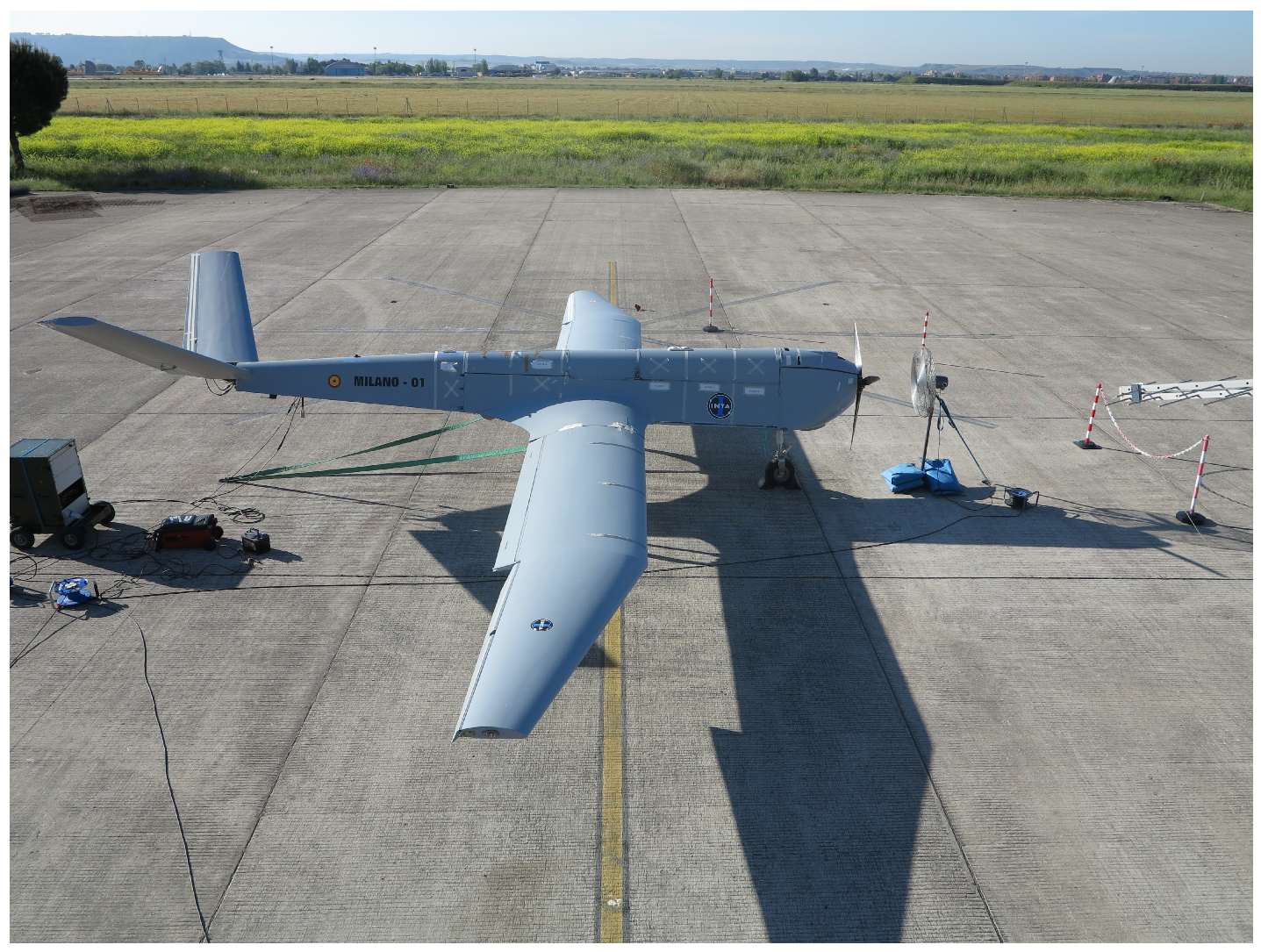
1. Introduction
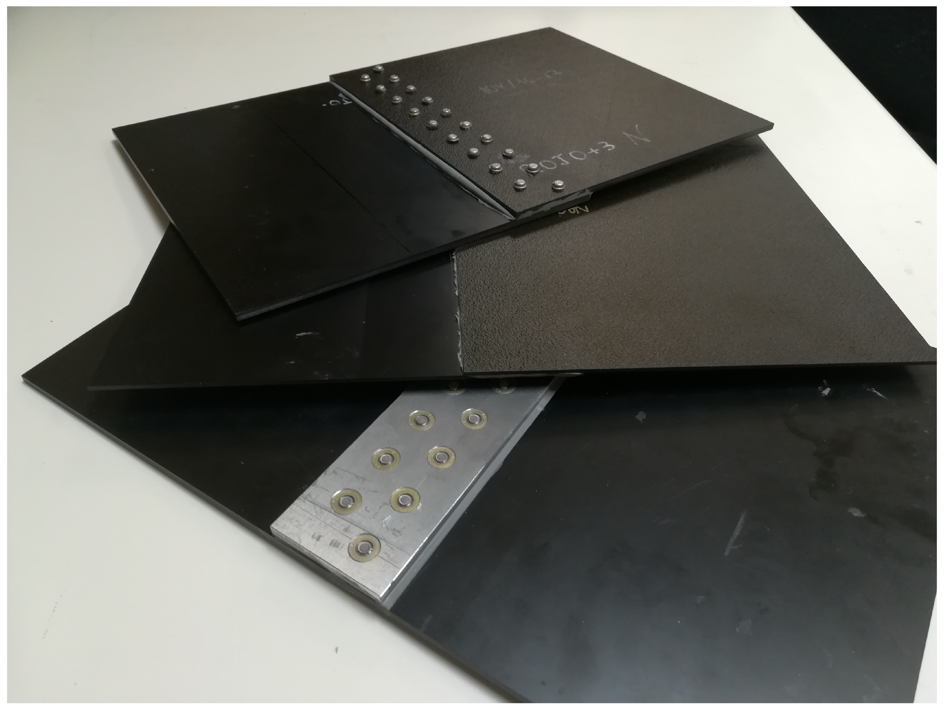
2. Test Samples
2.1. Materials
2.2. Joints
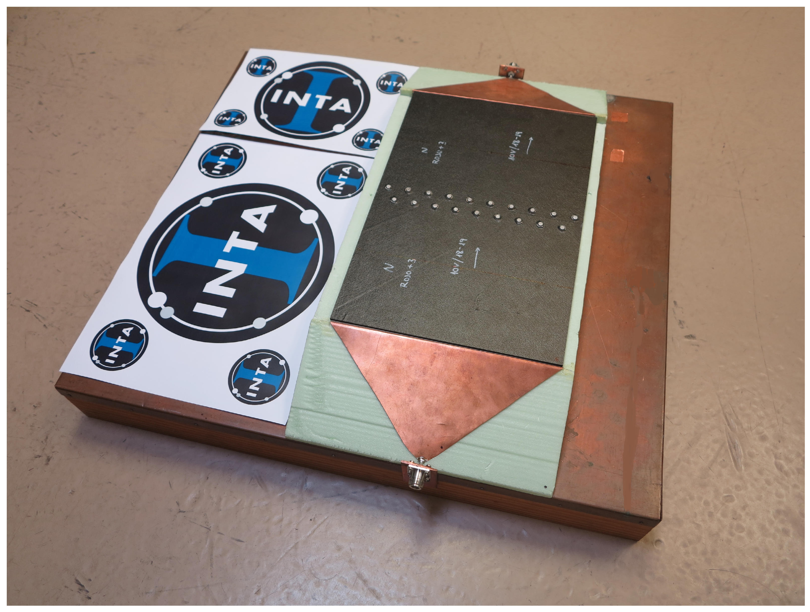
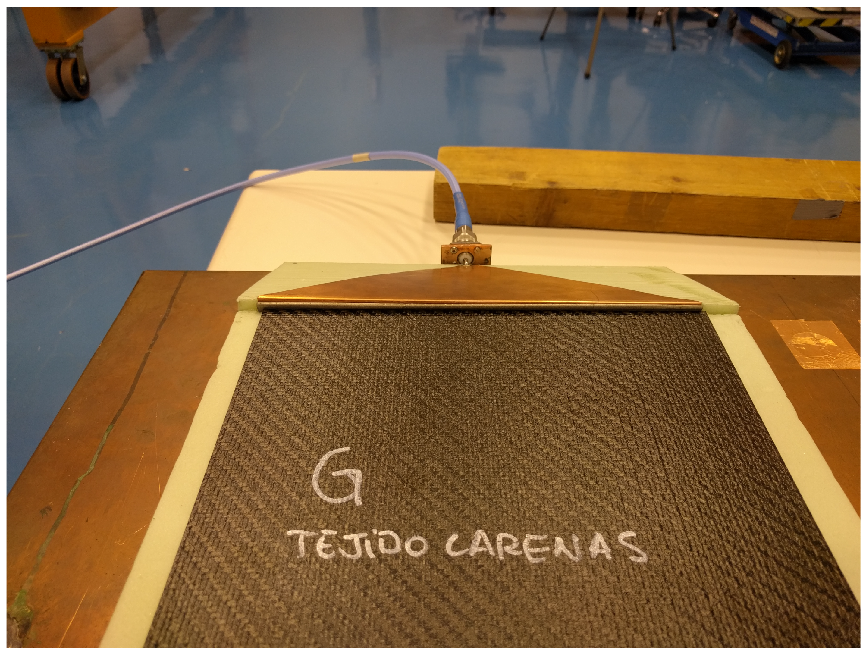
3. Measurement Methods
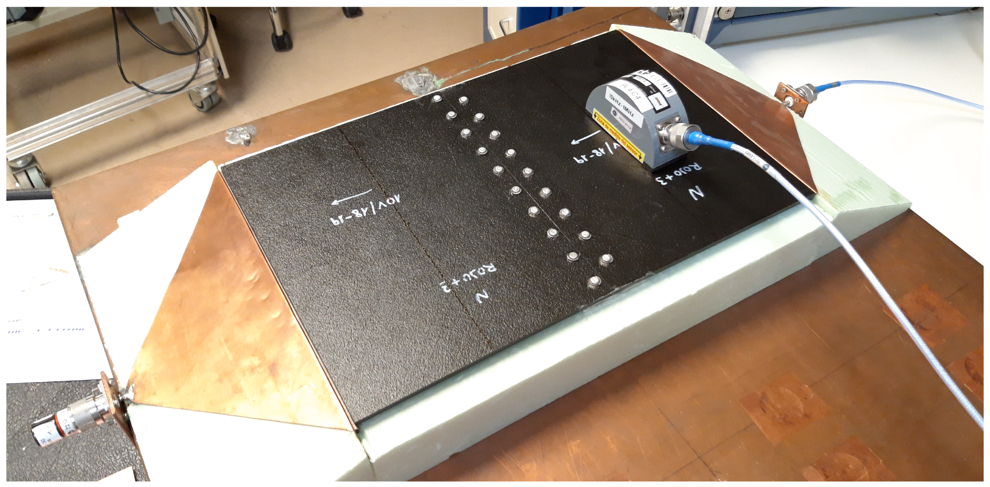
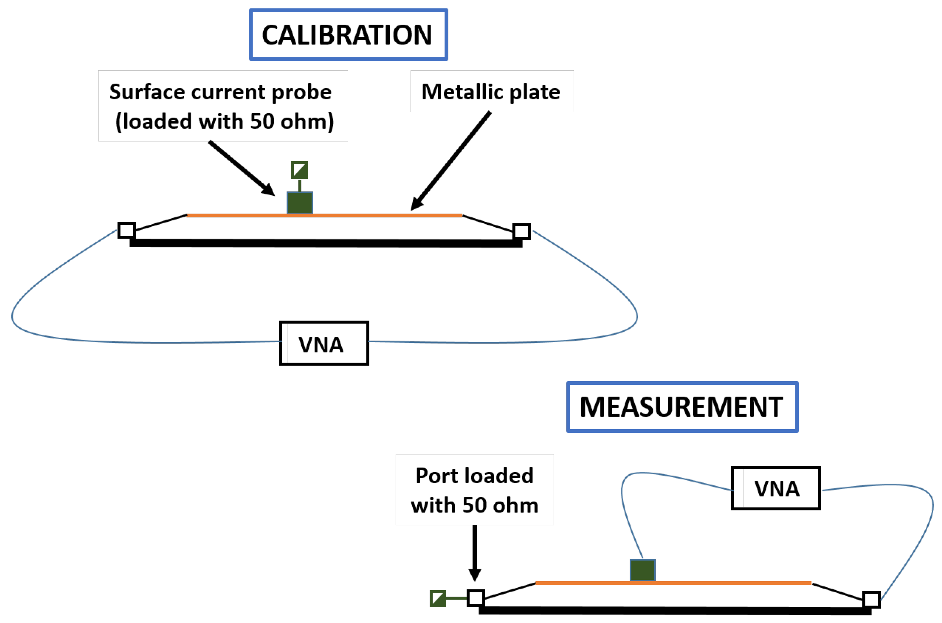
3.1. Test Setup
3.2. Measurements
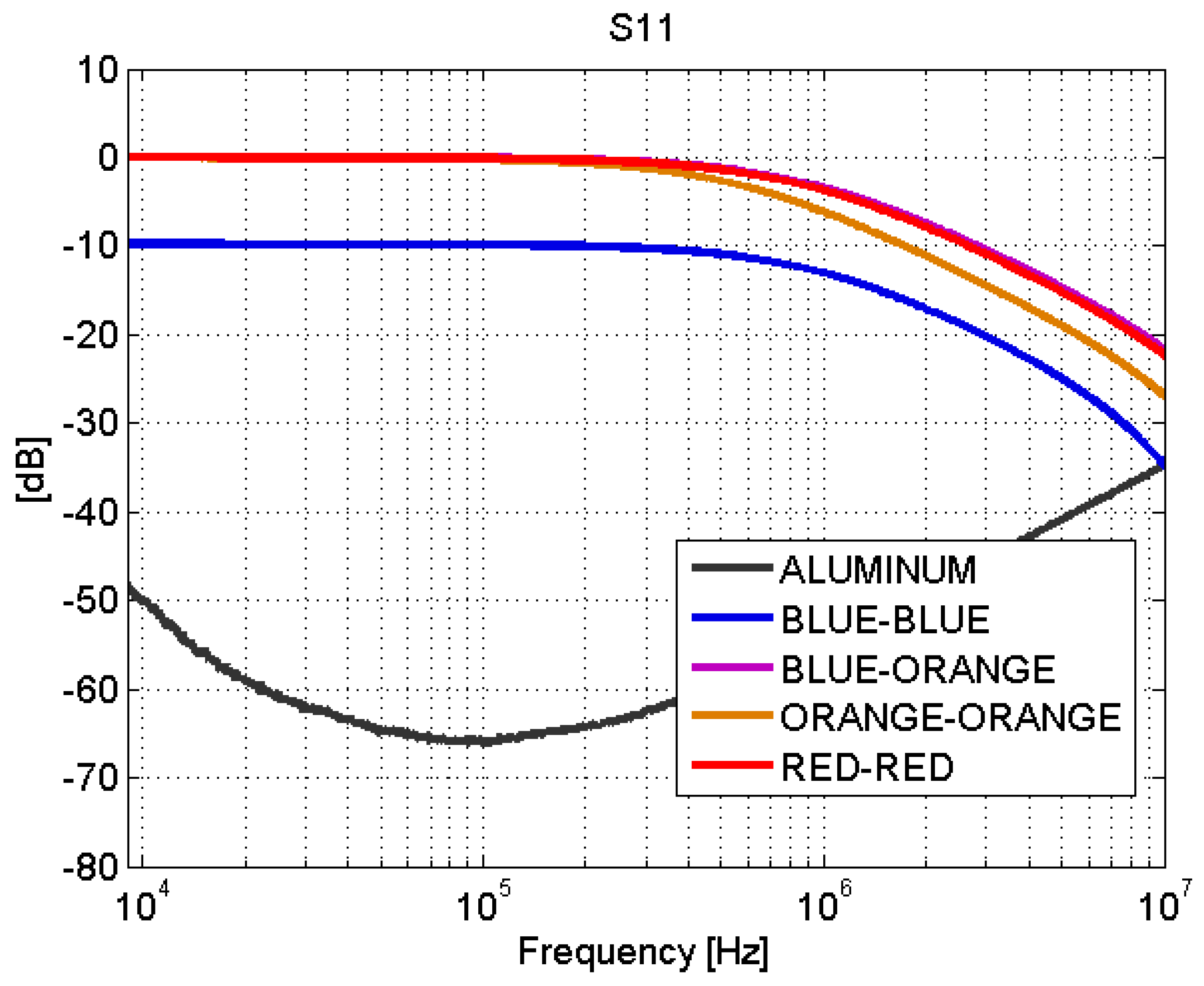
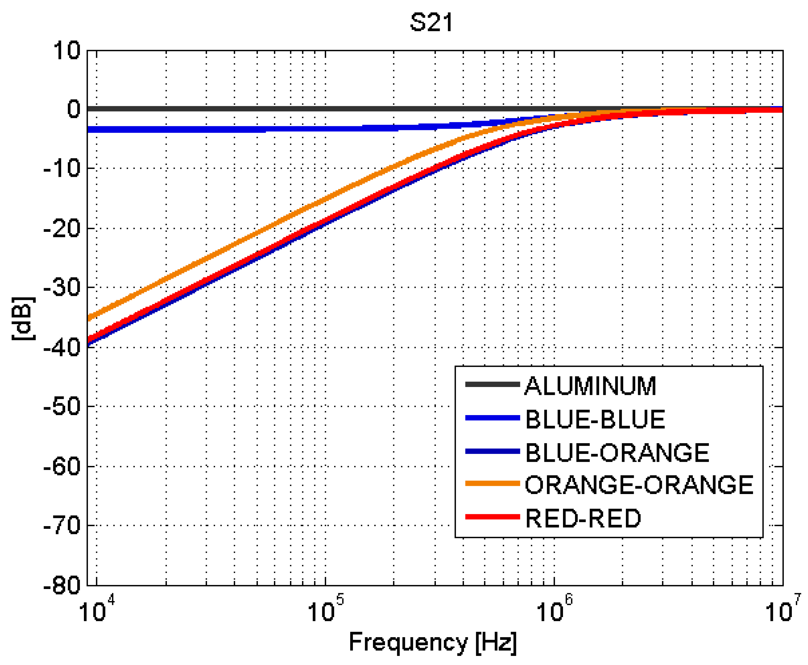
3.2.1. Scattering Parameters Measurements
3.2.2. Surface Current Measurements
4. Results
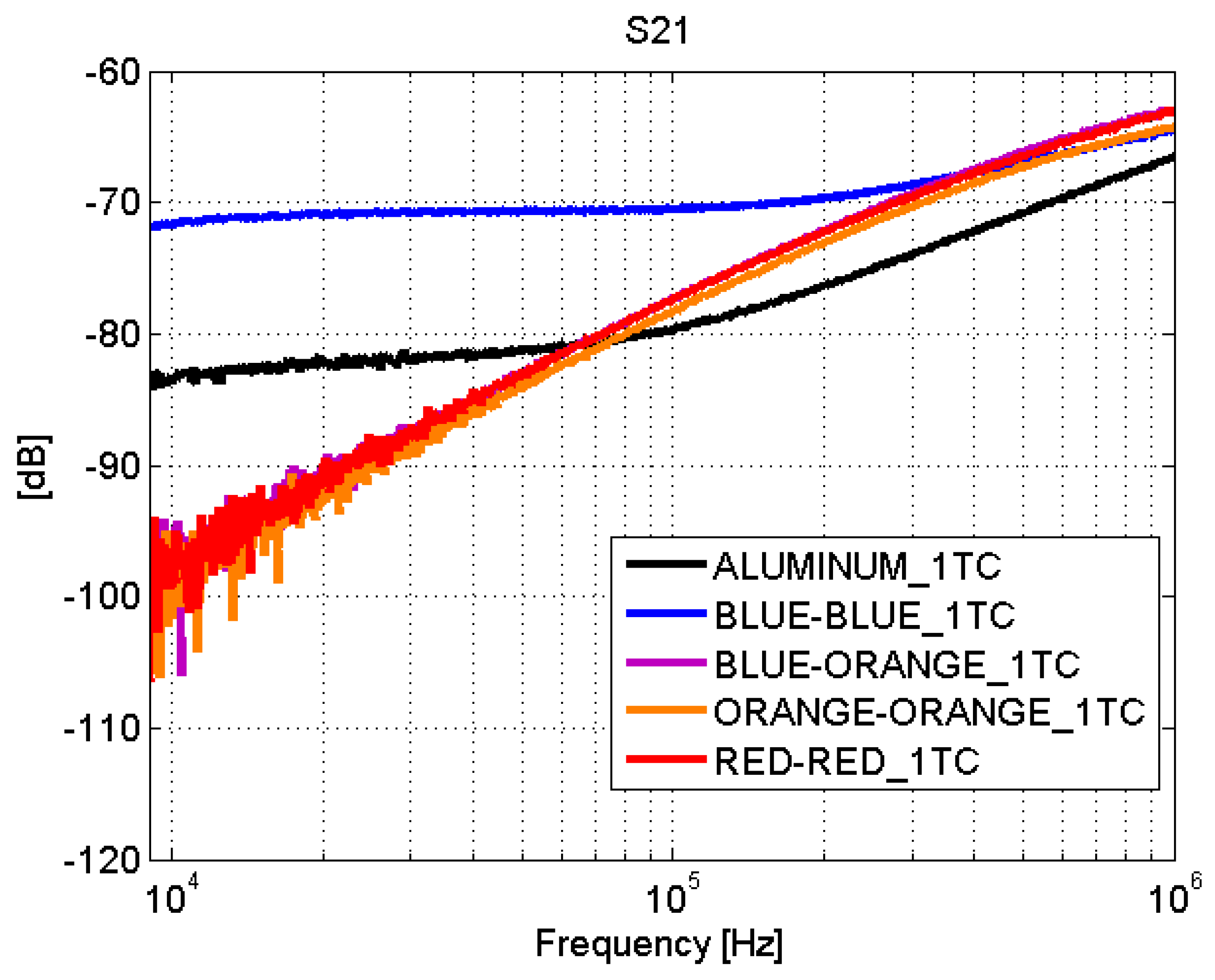
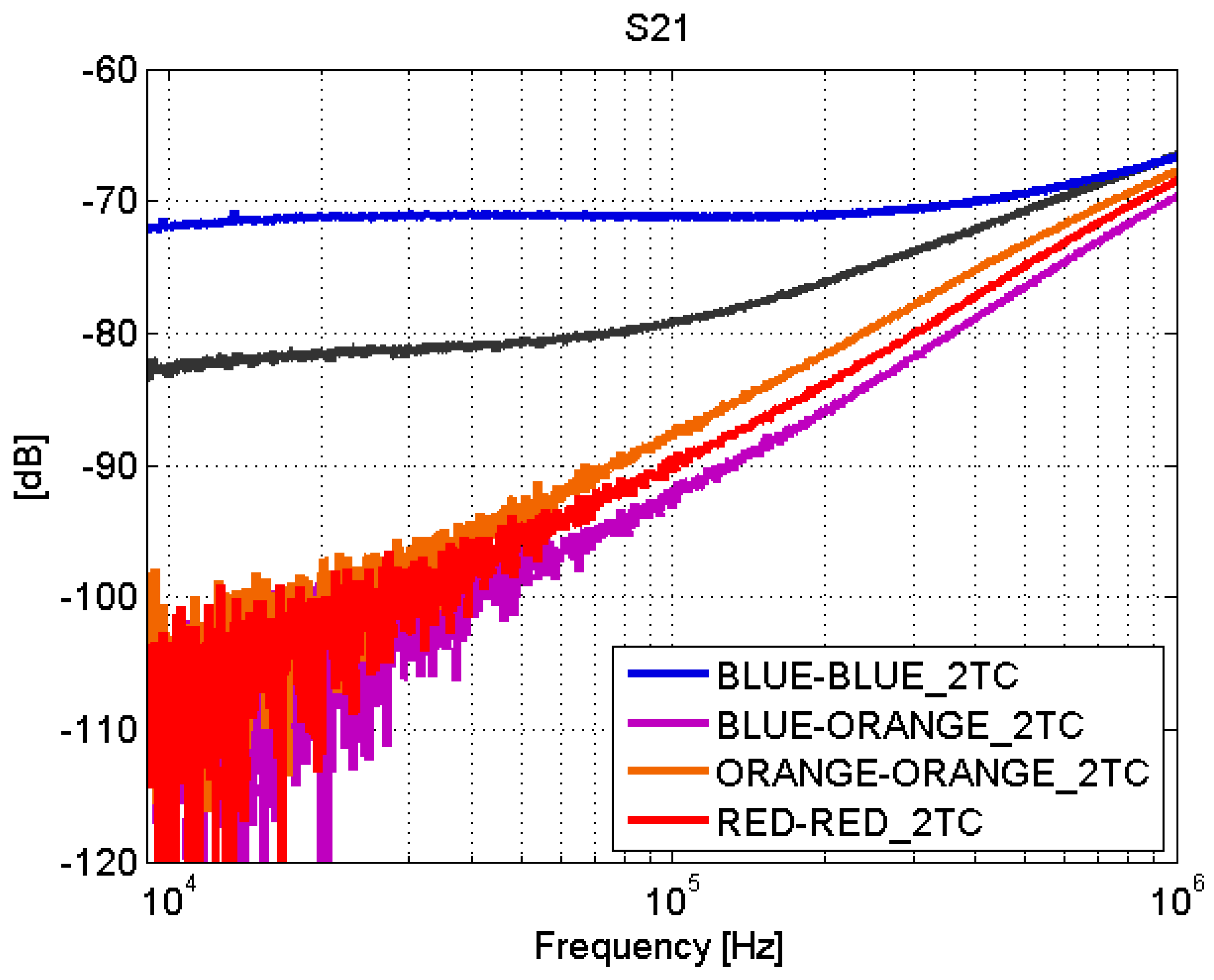
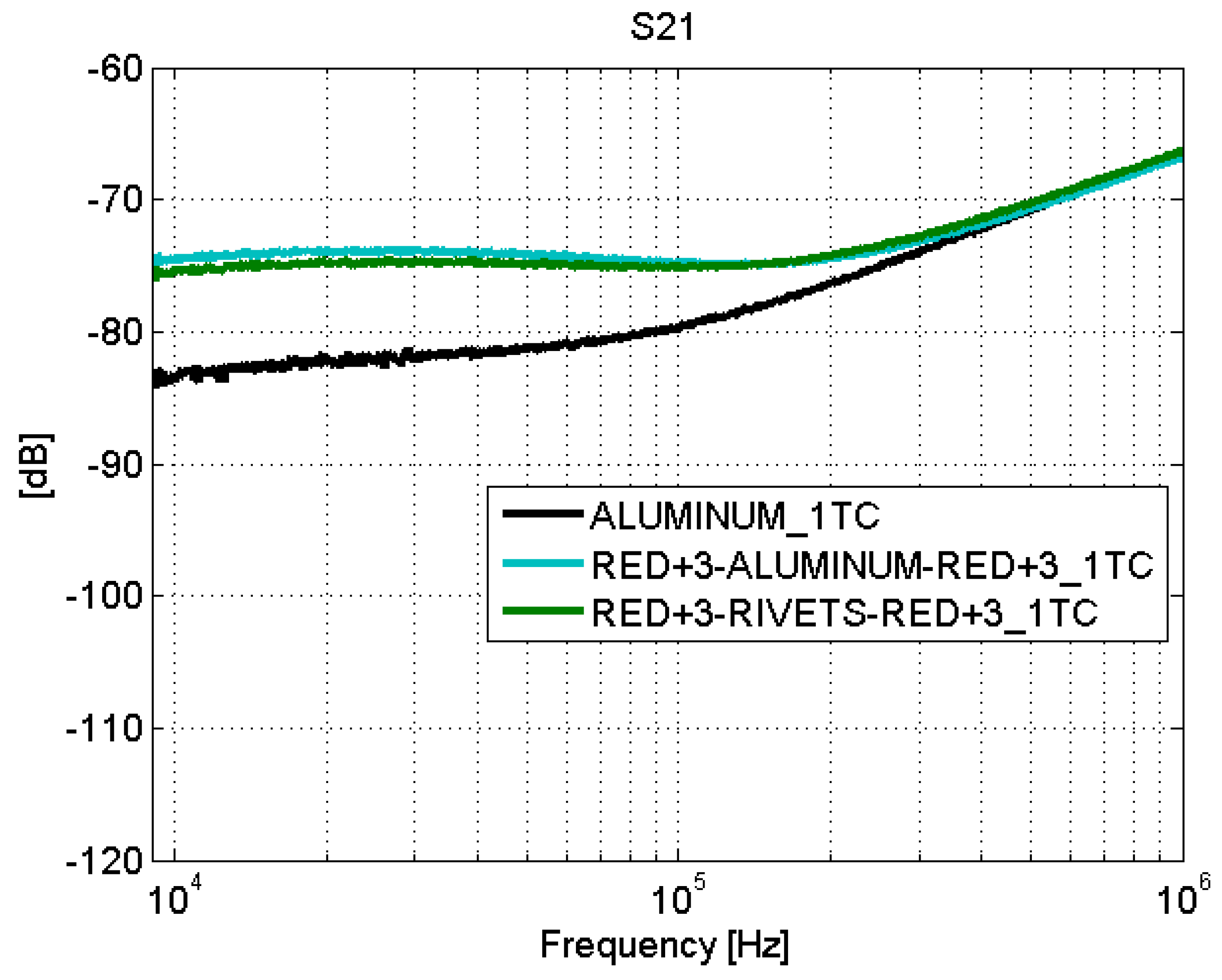
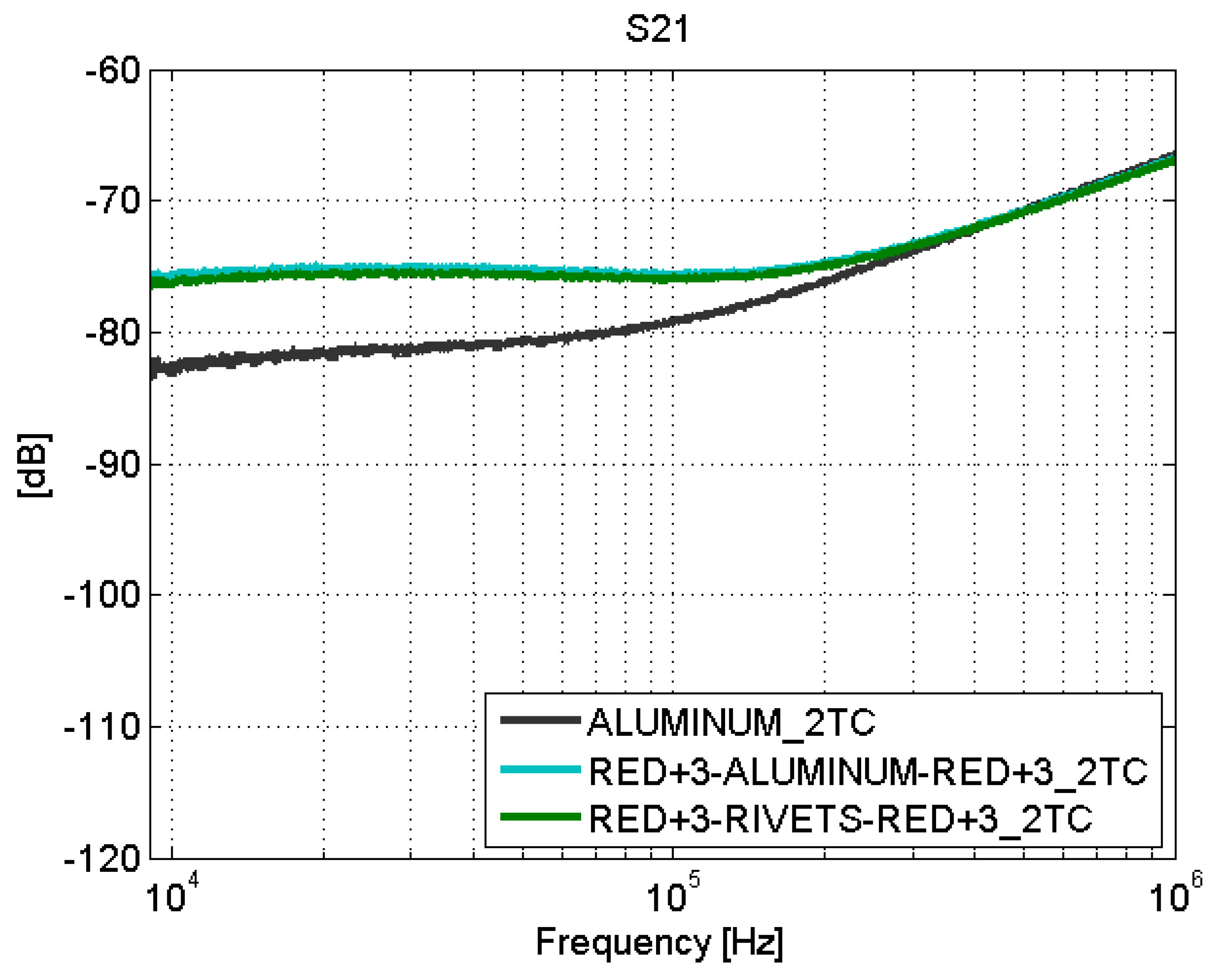
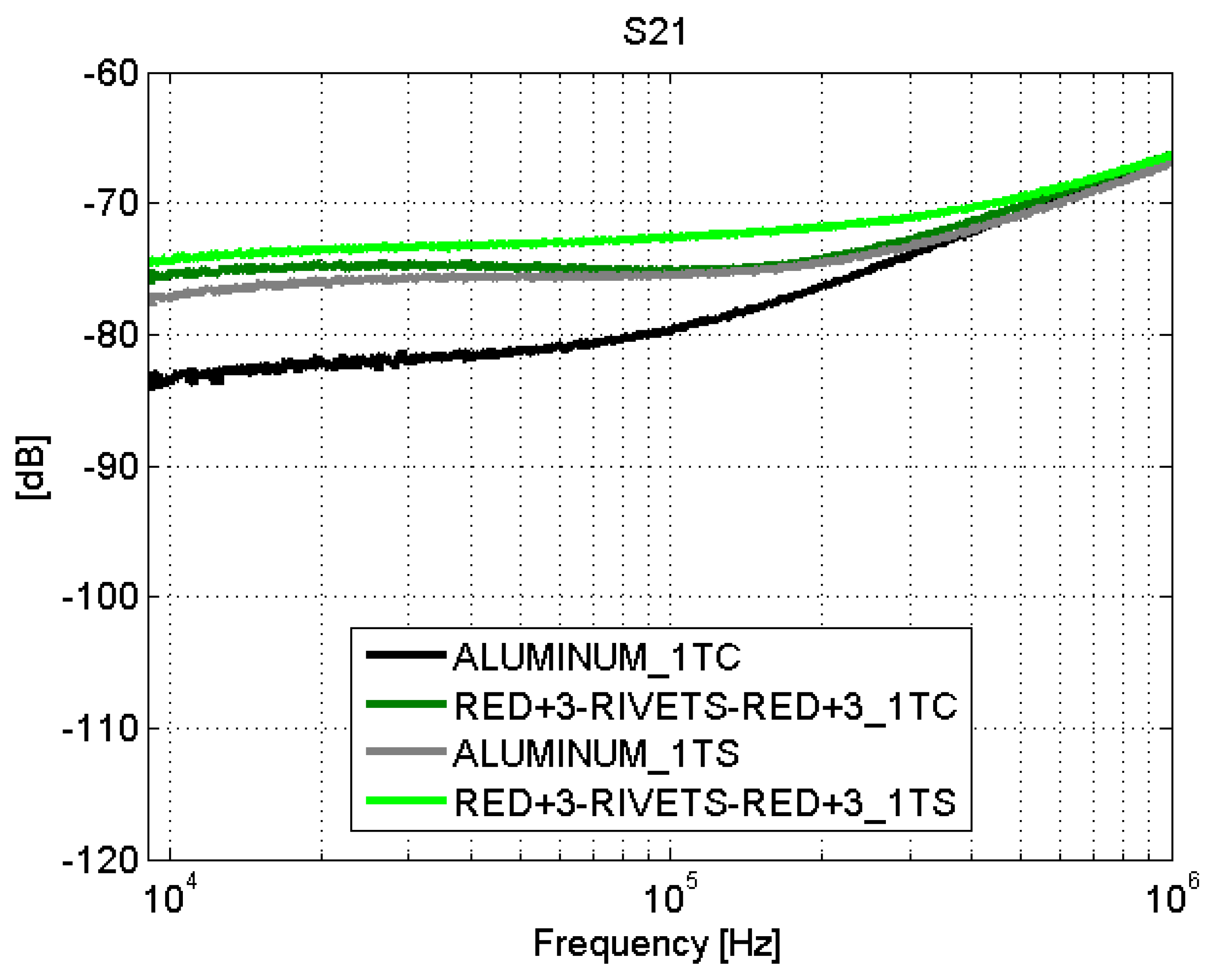
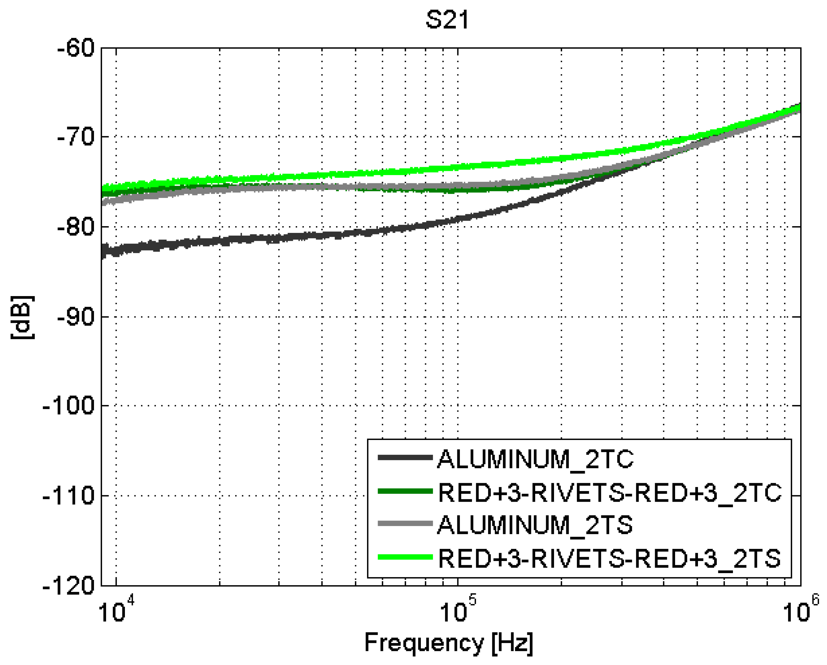
4.1. Scattering Parameter Measurements
4.2. Surface Current Measurements
5. Conclusions
Author Contributions
Funding
Institutional Review Board Statement
Informed Consent Statement
Data Availability Statement
Conflicts of Interest
References
- Nayak, N.V. Composite Materials in Aerospace Applications. Int. J. Sci. Res. Publ. 2014, 4, 2250–3153. [Google Scholar]
- Soutis, C. Carbon fiber reinforced plastics in aircraft construction. Mater. Sci. Eng. A 2005, 412, 171–176. [Google Scholar] [CrossRef]
- Lee, J.; Song, Y. Study of electromagnetic environmental effects on the airworthiness certification for performance improvement aircraft. In Proceedings of the 2017 International Symposium on Electromagnetic Compatibility—EMC EUROPE, Angers, France, 4–7 September 2017; pp. 1–6. [Google Scholar] [CrossRef]
- UAVE3. Numerical and Experimental Assessment of Electromagnetic Environmental Effects in Unmanned Aerial Vehicles. Available online: http://uave3.inta.es (accessed on 17 December 2020).
- Smorgonskiy, A.; Rachidi, F.; Rubinstein, M.; Korovkin, N.V.; Vassilopoulos, A.P. Are Standardized Lightning Current Waveforms Suitable for Aircraft and Wind Turbine Blades Made of Composite Materials? IEEE Trans. Electromagn. Compat. 2017, 59, 1320–1328. [Google Scholar] [CrossRef]
- Gao, R.X.; Lee, H.M.; Gao, S. Electromagnetic behavior analysis of aircraft composite under lightning direct effect. In Proceedings of the 2017 International Symposium on Electromagnetic Compatibility—EMC EUROPE, Angers, France, 4–7 September 2017; pp. 1–5. [Google Scholar] [CrossRef]
- Todoroki, A.; Ohara, K.; Mizutani, Y.; Suzuki, Y.; Matsuzaki, R. Lightning strike damage detection at a fastener using self-sensing TDR of composite plate. Compos. Struct. 2015, 132, 1105–1112. [Google Scholar] [CrossRef]
- Chen, L.; Ong, C.; Neo, C.; Varadan, V.; Varadan, V. Microwave Electronics. Measurement and Materials Characterization; John Wiley & Sons: Hoboken, NJ, USA, 2004. [Google Scholar]
- Hyde, M.W.; Havrilla, M.J.; Bogle, A.E.; Lehman, N.J. Broadband Characterization of Materials Using a Dual-Ridged Waveguide. IEEE Trans. Instrum. Meas. 2013, 62, 3168–3176. [Google Scholar] [CrossRef]
- Kempin, M.; Ghasr, M.T.; Case, J.T.; Zoughi, R. Modified Waveguide Flange for Evaluation of Stratified Composites. IEEE Trans. Instrum. Meas. 2014, 63, 1524–1534. [Google Scholar] [CrossRef]
- Hajisaeid, E.; Dericioglu, A.F.; Akyurtlu, A. All 3-D Printed Free-Space Setup for Microwave Dielectric Characterization of Materials. IEEE Trans. Instrum. Meas. 2018, 67, 1877–1886. [Google Scholar] [CrossRef]
- Galehdar, A.; Callus, P.J.; Ghorbani, K. A Novel Method of Conductivity Measurements for Carbon-Fiber Monopole Antenna. IEEE Trans. Antennas Propag. 2011, 59, 2120–2126. [Google Scholar] [CrossRef]
- Doan, T.; Walters, A.; Leat, C. Characterisation of electromagnetic properties of carbon fibre composite materials. In Proceedings of the 2009 Electromagnetic Compatibility Symposium Adelaide, Adelaide, SA, Australia, 16 August–18 September 2009; pp. 87–91. [Google Scholar]
- Bui, H.K.; Senghor, F.D.; Wasselynck, G.; Trichet, D.; Fouladgar, J.; Lee, K.; Berthiau, G. Characterization of Electrical Conductivity of Anisotropic CFRP Materials by Means of Induction Thermography Technique. IEEE Trans. Magn. 2018, 54, 1–4. [Google Scholar] [CrossRef]
- Tamburrano, A.; Desideri, D.; Maschio, A.; Sarto, M.S. Coaxial Waveguide Methods for Shielding Effectiveness Measurement of Planar Materials Up to 18 GHz. IEEE Trans. Electromagn. Compat. 2014, 56, 1386–1395. [Google Scholar] [CrossRef]
- Diaz Angulo, L.M.; de Francisco, P.G.; Gallardo, B.P.; Martinez, D.P.; Cabello, M.R.; Bocanegra, D.E.; Garcia, S.G. Modeling and Measuring the Shielding Effectiveness of Carbon Fiber Composites. IEEE J. Multiscale Multiphys. Comput. Tech. 2019, 4, 207–213. [Google Scholar] [CrossRef]
- Schmick, F.; Lüders, N.O.; Wollnack, J. Automated assembly of large CFRP structures: Adaptive filling of joining gaps with additive manufacturing. In Proceedings of the 2016 IEEE International Symposium on Assembly and Manufacturing (ISAM), Fort Worth, TX, USA, 21–22 August 2016; pp. 126–132. [Google Scholar] [CrossRef]
- Tavares, S.M.O. Design and Advanced Manufacturing of Aircraft Structures using Friction Stir Welding. Ph.D. Thesis, Faculty of Engineering of the University of Porto, Porto, Portugal, 2011. [Google Scholar]
- Holden, R.; Haworth, P.; Kendrick, I.; Smith, A. Automated Riveting Cell for A320 Wing Panels with Improved Throughput and Reliability (SA2); SAE Technical Paper; SAE International: Warrendale, PA, USA, 2007. [Google Scholar] [CrossRef]
- Higgins, A. Adhesive bonding of aircraft structures. Int. J. Adhes. Adhes. 2000, 20, 367–376. [Google Scholar] [CrossRef]
- Petrie, E.M. Adhesives for the assembly of aircraft structures and components: Decades of performance improvement, with the new applications of the horizon. Met. Finish. 2008, 106, 26–31. [Google Scholar] [CrossRef]
- Romero, S.F.; Rodríguez, P.L.; Bocanegra, D.E.; Martínez, D.P.; Cancela, M.A. Comparing Open Area Test Site and Resonant Chamber for Unmanned Aerial Vehicle’s High-Intensity Radiated Field Testing. IEEE Trans. Electromagn. Compat. 2018, 60, 1704–1711. [Google Scholar] [CrossRef]
- Lodge, K. The electrical properties of joints in carbon fibre composites. Composites 1982, 13, 305–310. [Google Scholar] [CrossRef]
- Shimamura, Y.; Oda, K.; Todoroki, A.; Kobayashi, H.; Inada, T. Application of Electric Resistance Change Method to Damage Detection of CFRP Bolted Joints. In Advances in Fracture and Strength; Trans Tech Publications Ltd.: Stafa-Zurich, Switzerland, 2005; Volume 297, pp. 653–658. [Google Scholar] [CrossRef]
- Shimamura, Y.; Oda, K.; Todoroki, A.; Ueda, M. Detectability of Bearing Failure of Composite Bolted Joints by Electric Resistance Change Method. Key Eng. Mater. 2006, 321–323, 957–962. [Google Scholar] [CrossRef]
- Brettle, J.; Lodge, K.J.; Poole, R. The electrical effects of joints and bonds in carbon fibre composites. In Proceedings of the AGARD Conference Proceedings CP-283, Lisbon, Portugal, 16–19 June 1980. [Google Scholar]
- Chung, J.; Sertel, K.; Volakis, J.L. Broadband Characterization of Bulk and Thin Magnetic Composites Using Stripline Structures. IEEE Trans. Microw. Theory Tech. 2010, 58, 2960–2967. [Google Scholar] [CrossRef]
- Tiwari, N.K.; Singh, S.P.; Akhtar, M.J. Novel Microstrip-Based Simplified Approach for Fast Determination of Substrate Permittivity. IEEE Trans. Components Packag. Manuf. Technol. 2018, 8, 660–669. [Google Scholar] [CrossRef]
- Todoroki, A.; Yamada, K.; Mizutani, Y.; Suzuki, Y.; Matsuzaki, R.; Fujita, H. Self-Sensing Curved Micro-Strip Line Method for Damage Detection of CFRP Composites. Open J. Compos. Mater. 2014, 4, 131–139. [Google Scholar] [CrossRef]
- Pozar, D.M. Microwave Engineering, 2nd ed.; Wiley: Hoboken, NJ, USA, 1998; pp. 196–205. [Google Scholar]
- Aluminum 7075-T6. ASM Aerospace Specification Metal INC. Available online: http://asm.matweb.com/search/SpecificMaterial.asp?bassnum=MA7075T6 (accessed on 17 December 2020).
- BASF Products—Styrodur. Available online: www.styrodur.com/ (accessed on 17 December 2020).
- Wheeler, H.A. Transmission-Line Properties of a Strip on a Dielectric Sheet on a Plane. IEEE Trans. Microw. Theory Tech. 1977, 25, 631–647. [Google Scholar] [CrossRef]
- Borgstrom, E.J. An overview of the EMC requirements in RTCA/DO-160D. In Proceedings of the 1998 IEEE EMC Symposium. International Symposium on Electromagnetic Compatibility, Symposium Record (Cat. No.98CH36253), Denver, CO, USA, 24–28 August 1998; Volume 2, pp. 702–707. [Google Scholar]
- RTCA, I. Environmental Conditions and Test Procedures for Airborne Equipment; Technical Report; RTCA, Inc.: Washington, DC, USA, 2007. [Google Scholar]
- Surface Monitor Probes F90. Fischer Custom Communications, INC. Available online: https://www.fischercc.com/products/f-90-1/ (accessed on 17 December 2020).
- Henkel, Adhesive Technologies. Structural Adhesives for Aircrafts. Available online: https://www.henkel-adhesives.com/us/en/industries/aerospace.html (accessed on 17 December 2020).


| Material | Stacking Sequence | Nº of Plies |
|---|---|---|
| red | [+45/−45/0/−45/+45/90/90/+45/−45/0/−45/+45] | 12 |
| orange | [+45/−45/+45/0/+45/90/+45/0/−45/−45/0/+45/90/+45/0/+45/−45/+45] | 18 |
| blue | [+45/−45/−45/0/+45/90/+45/0/−45/−45/0/+45/90/+45/0/−45/−45/+45] | 18 |
| [+45/−45/0/−45/+45/90/90/+45/−45/0/−45/+45] | ||
| red+3 | [+45/−45/0/−45/+45/90/90/+45/−45/0/−45/+45] | 36 |
| [+45/−45/0/−45/+45/90/90/+45/−45/0/−45/+45] |
Publisher’s Note: MDPI stays neutral with regard to jurisdictional claims in published maps and institutional affiliations. |
© 2021 by the authors. Licensee MDPI, Basel, Switzerland. This article is an open access article distributed under the terms and conditions of the Creative Commons Attribution (CC BY) license (http://creativecommons.org/licenses/by/4.0/).
Share and Cite
Plaza, B.; López, D.; Poyatos, D. Characterization of Joints between Carbon Fiber Composite Parts Using a Microstrip Transmission Line Method. Sensors 2021, 21, 1142. https://doi.org/10.3390/s21041142
Plaza B, López D, Poyatos D. Characterization of Joints between Carbon Fiber Composite Parts Using a Microstrip Transmission Line Method. Sensors. 2021; 21(4):1142. https://doi.org/10.3390/s21041142
Chicago/Turabian StylePlaza, Borja, Daniel López, and David Poyatos. 2021. "Characterization of Joints between Carbon Fiber Composite Parts Using a Microstrip Transmission Line Method" Sensors 21, no. 4: 1142. https://doi.org/10.3390/s21041142
APA StylePlaza, B., López, D., & Poyatos, D. (2021). Characterization of Joints between Carbon Fiber Composite Parts Using a Microstrip Transmission Line Method. Sensors, 21(4), 1142. https://doi.org/10.3390/s21041142