
Automated Curb Recognition and Negotiation for Robotic Wheelchairs

 , , , , and
Abstract
:1. Introduction
- The first fully integrated open-source autonomous framework for a curb climbing robotic wheelchair was validated experimentally (Castagno and Sivakanthan 2021, https://github.com/sivashankar28/polylidar-realsense-wheelchair, (accessed on 20 October 2021)).
- A novel and robust curb-edge detection method that extracts a curb edge from the polygonal representation of the sidewalk surface. Standard line extraction methods are significantly more efficient by operating on a low-dimensional polygon instead of dense image space.
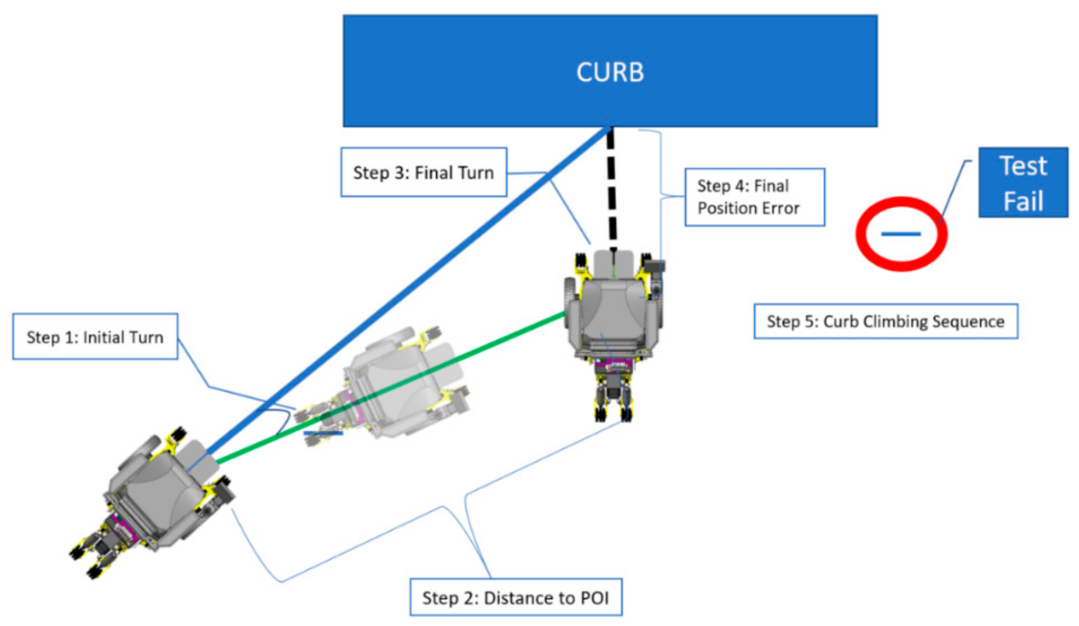
- An automated-driving three-step sequence that uses the curb characteristics to drive and negotiate using an existing curb climbing sequence.
2. Materials and Methods
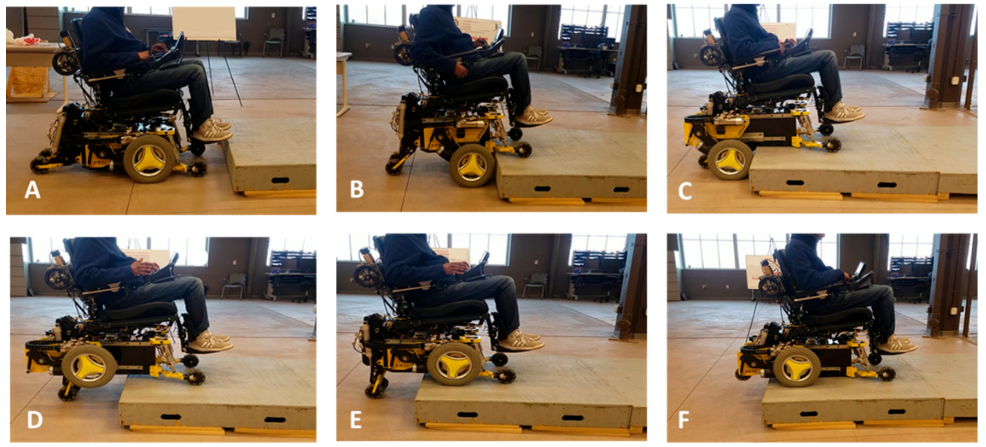
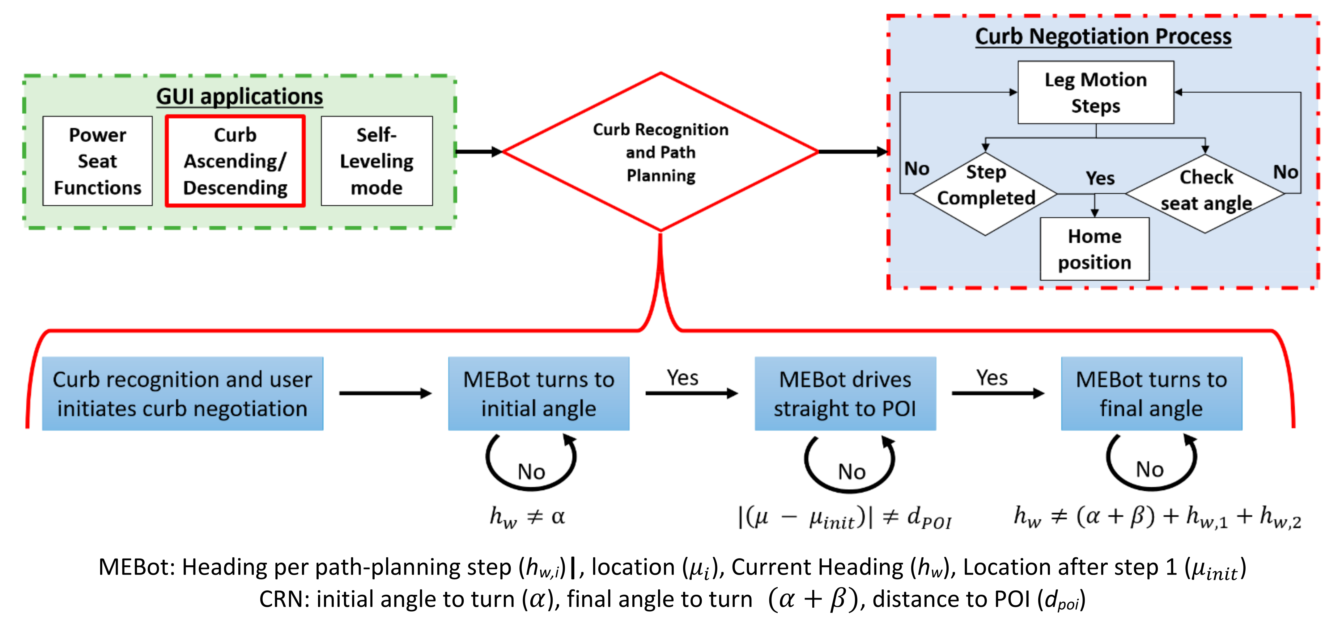
2.1. Previous MEBot Curb Recognition and Negotiation System
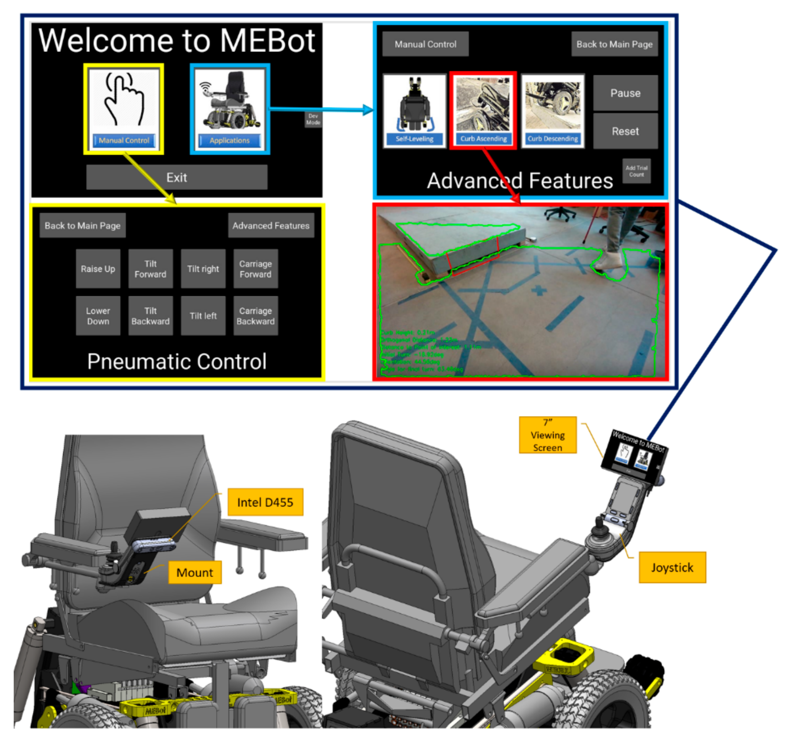
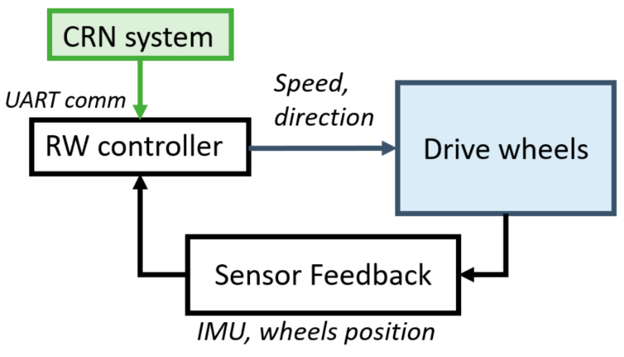
2.2. CRN Hardware and Software Development
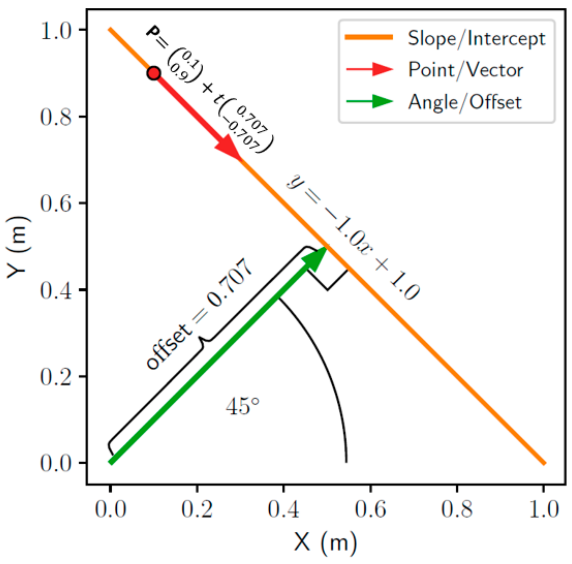
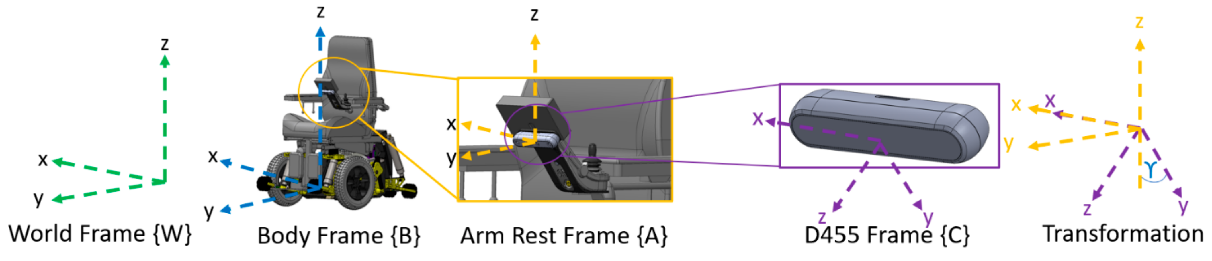
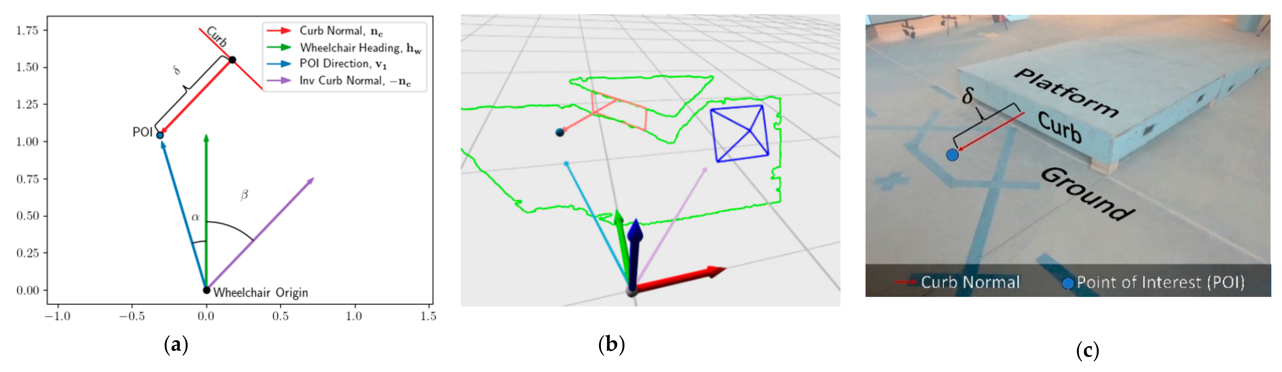
2.3. Preliminaries
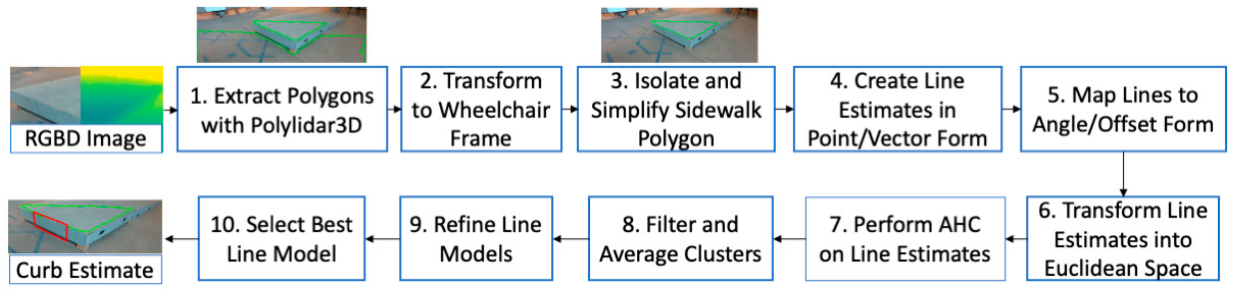
2.4. Curb Negotiation and Classifying the Ground and Sidewalk Planes
2.5. Path-Planning Algorithm
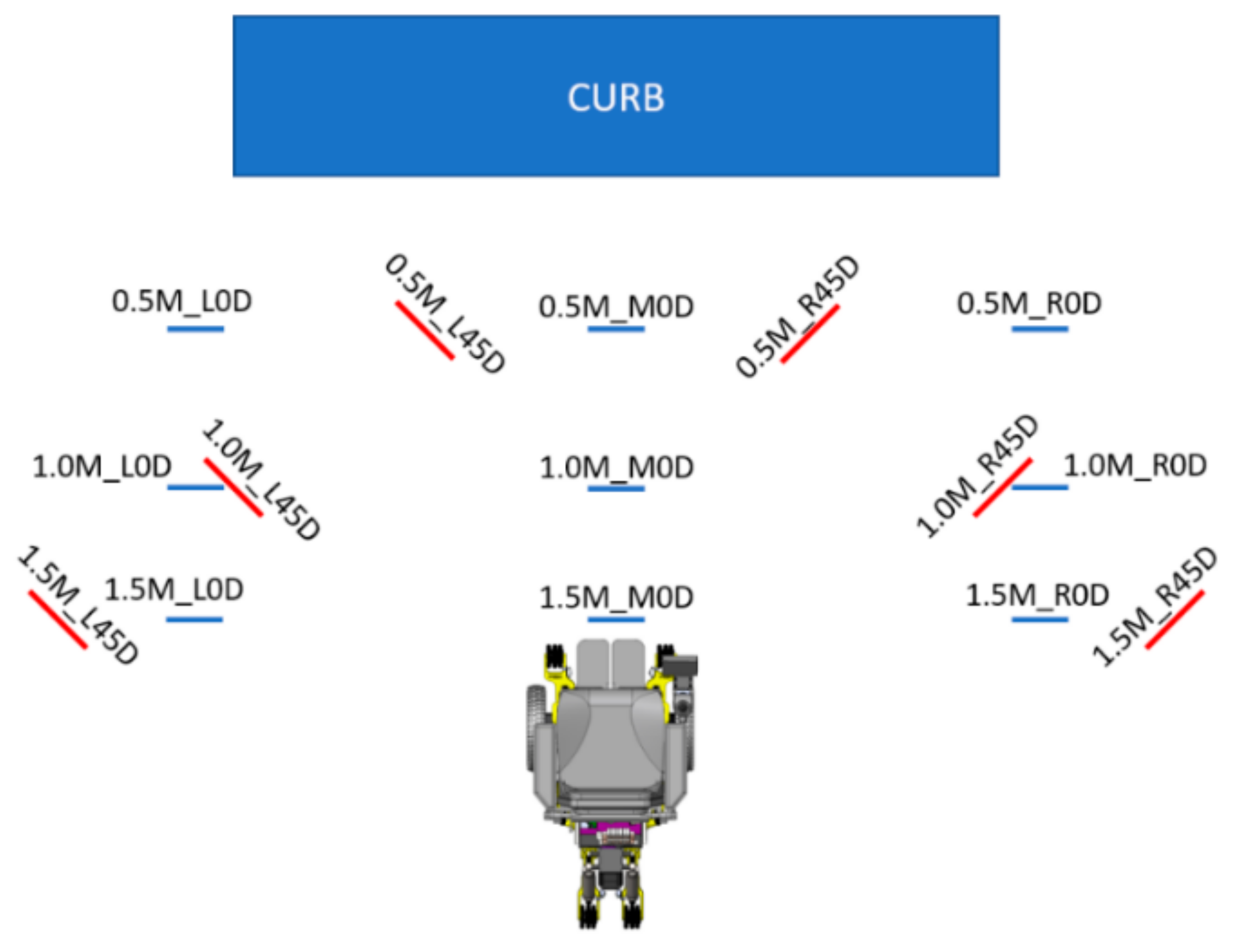
2.6. Experimental Protocol
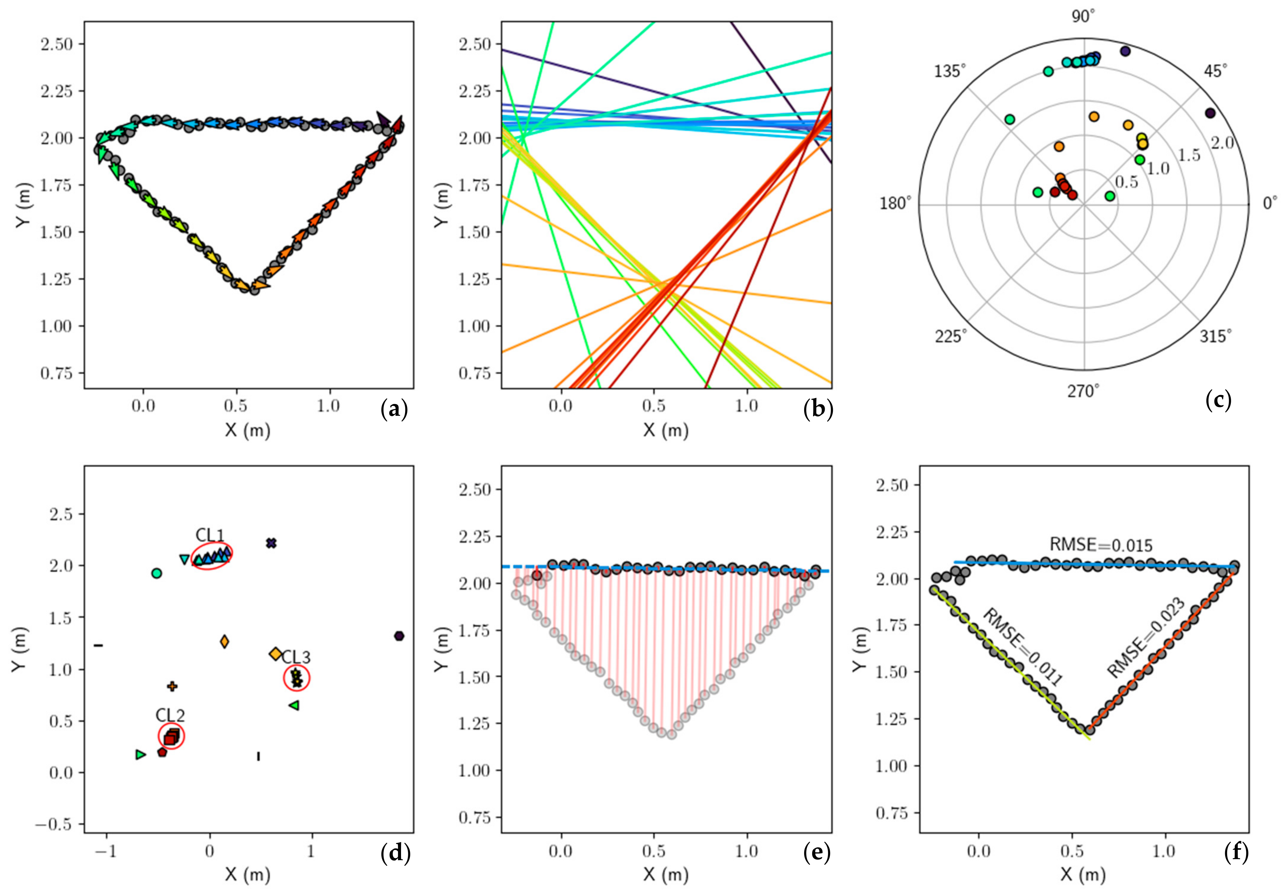
2.7. Data Analysis
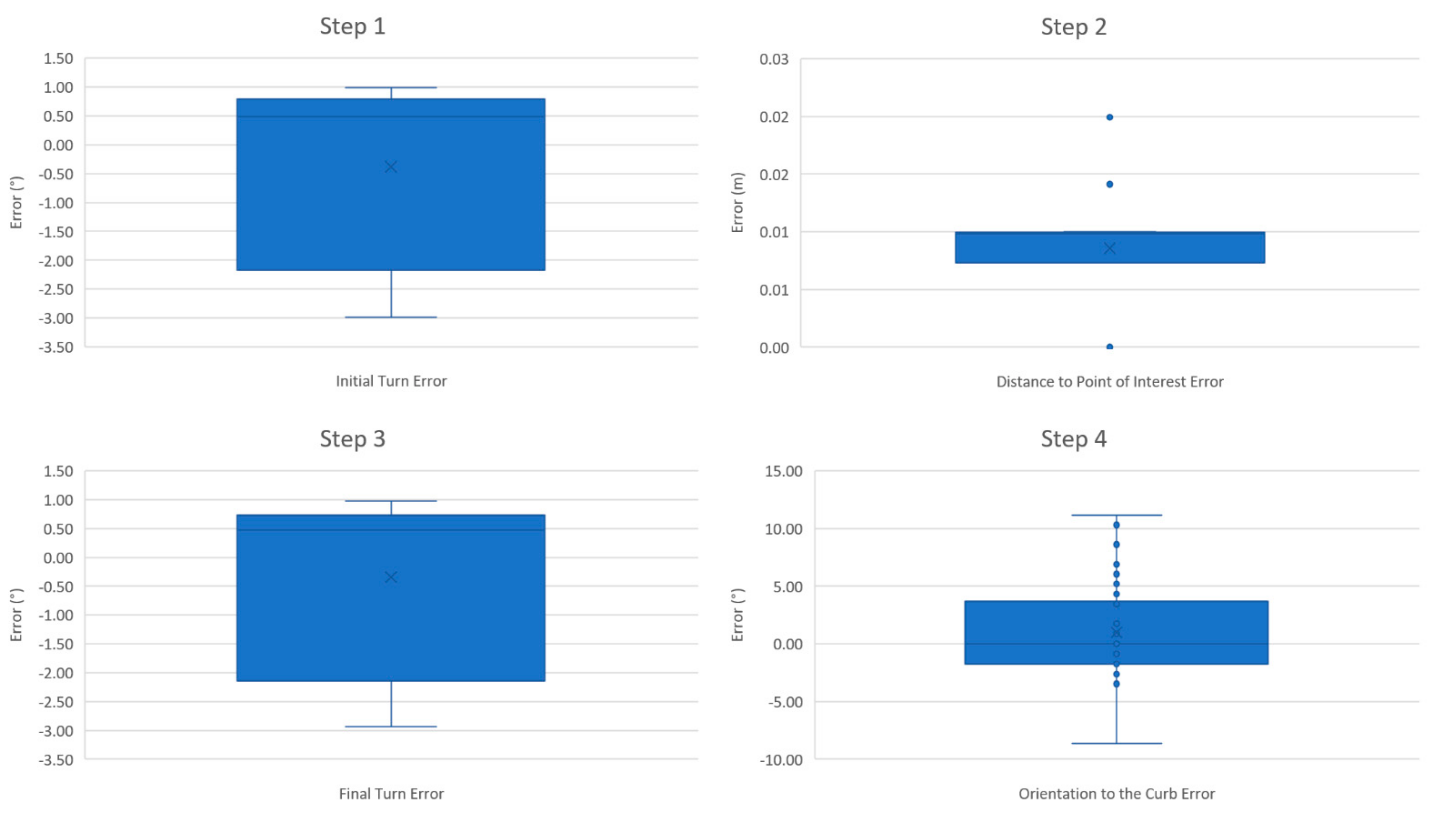
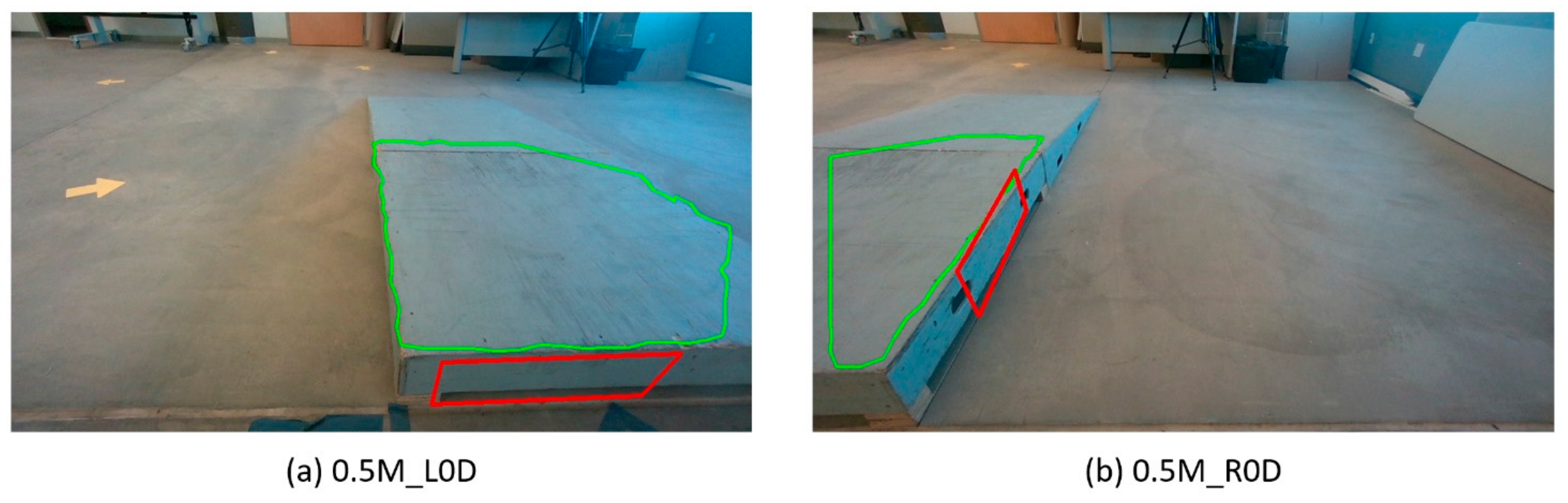
3. Results
4. Discussion
4.1. Perception-Based Reliability
4.2. Pre-Planning Process
4.3. Future Work
5. Conclusions
6. Patents
Author Contributions
Funding
Institutional Review Board Statement
Informed Consent Statement
Data Availability Statement
Conflicts of Interest
References
- Cooper, R.A.; Cooper, R.; Boninger, M.L. Trends and issues in wheelchair technologies. Assist. Technol. 2008, 20, 61–72. [Google Scholar] [CrossRef]
- Gavin-Dreschnack, D.; Nelson, A.; Fitzgerald, S.; Harrow, J.; Sanchez-Anguiano, A.; Ahmed, S.; Powell-Cope, G. Wheelchair-related Falls: Current Evidence and Directions for Improved Quality Care. J. Nurs. Care Qual. 2005, 20, 119–127. [Google Scholar] [CrossRef]
- Bennett, S.; Lee Kirby, R.; Macdonald, B. Wheelchair accessibility: Descriptive survey of curb ramps in an urban area. Disabil. Rehabil. Assist. Technol. 2009, 4, 17–23. [Google Scholar] [CrossRef] [PubMed]
- Henderson, G.V.; Boninger, M.L.; Dicianno, B.E.; Worobey, L.A. Type and frequency of wheelchair repairs and resulting adverse consequences among veteran wheelchair users. Disabil. Rehabil. Assist. Technol. 2020, 1–7. [Google Scholar] [CrossRef] [PubMed]
- Routhier, F.; Vincent, C.; Desrosiers, J.; Nadeau, S.; Guerette, C. Development of an obstacle course assessment of wheelchair user performance (OCAWUP): A content validity study. Technol. Disabil. 2004, 16, 19–31. [Google Scholar] [CrossRef]
- Edwards, K.; Mccluskey, A. A Survey of Adult Power Wheelchair and Scooter Users. Disabil Rehabil Assist Technol. 2010, 5, 411–419. [Google Scholar] [CrossRef]
- Officials, T. A Policy on Geometric Design of Highways and Streets, 2011; AASHTO: Washington, DC, USA, 2011. [Google Scholar]
- Sundaram, S.A.; Wang, H.; Ding, D.; Cooper, R.A. Step-Climbing Power Wheelchairs: A Literature Review. Top. Spinal Cord Inj. Rehabil. 2017, 23, 98–109. [Google Scholar] [CrossRef] [Green Version]
- Chocoteco, J.; Morales, R.; Feliu, V.; Sanchez, L. Trajectory Planning for a Stair-Climbing Mobility System Using Laser Distance Sensors. IEEE Syst. J. 2016, 10, 944–956. [Google Scholar] [CrossRef]
- Mobility Mobius. iBot. 2019. Available online: http://mobiusmobility.com/ (accessed on 15 May 2019).
- Nakajima, S. A New Personal Mobility Vehicle for Daily Life Improvements on a new RT-Mover that enable greater mobility are showcased at the Cybathlon. IEEE Robot. Autom. Mag. 2017, 24, 37–48. [Google Scholar] [CrossRef]
- Simpson, R.C.; LoPresti, E.F.; Cooper, R.A. How many people would benefit from a smart wheelchair? J. Rehabil. Res. Dev. 2008, 45, 53–71. [Google Scholar] [CrossRef] [PubMed]
- Sanfilippo, F.; Azpiazu, J.; Marafioti, G.; Transeth, A.A.; Stavdahl, Ø.; Liljebäck, P. Perception-driven obstacle-aided locomotion for snake robots: The state of the art, challenges and possibilities. Appl. Sci. 2017, 7, 336. [Google Scholar] [CrossRef]
- Romero, L.M.; Guerrero, J.A.; Romero, G. Road Curb Detection: A Historical Survey. Sensors 2021, 21, 6952. [Google Scholar] [CrossRef] [PubMed]
- Rhee, J.H.; Seo, J. Low-cost curb detection and localization system using multiple ultrasonic sensors. Sensors 2019, 19, 1389. [Google Scholar] [CrossRef] [PubMed] [Green Version]
- Zhang, Y.; Wang, J.; Wang, X.; Dolan, J.M. Road-segmentation-based curb detection method for self-driving via a 3D-LiDAR sensor. IEEE Trans. Intell. Transp. Syst. 2018, 19, 3981–3991. [Google Scholar] [CrossRef]
- Chen, T.; Dai, B.; Liu, D.; Song, J.; Liu, Z. Velodyne-based curb detection up to 50 meters away. In Proceedings of the 2015 IEEE Intelligent Vehicles Symposium (IV), Seoul, Korea, 28 June–1 July 2015. [Google Scholar]
- Hata, A.Y.; Osorio, F.S.; Wolf, D.F. Robust curb detection and vehicle localization in urban environments. In Proceedings of the 2014 IEEE Intelligent Vehicles Symposium Proceedings, Dearborn, MI, USA, 8–11 June 2014. [Google Scholar]
- Wang, T.-M.; Shih, Z.-C. Measurement and Analysis of Depth Resolution Using Active Stereo Cameras. IEEE Sens. J. 2021, 21, 9218–9230. [Google Scholar] [CrossRef]
- Goga, S.E.C.; Nedevschi, S. Fusing semantic labeled camera images and 3D LiDAR data for the detection of urban curbs. In Proceedings of the 2018 IEEE 14th International Conference on Intelligent Computer Communication and Processing (ICCP), Cluj-Napoca, Romania, 6–8 September 2018. [Google Scholar]
- Deac, S.E.C.; Giosan, I.; Nedevschi, S. Curb detection in urban traffic scenarios using LiDARs point cloud and semantically segmented color images. In Proceedings of the 2019 IEEE Intelligent Transportation Systems Conference (ITSC), Auckland, New Zealand, 27–30 October 2019. [Google Scholar]
- De Silva, V.; Roche, J.; Kondoz, A. Robust fusion of LiDAR and wide-angle camera data for autonomous mobile robots. Sensors 2018, 18, 2730. [Google Scholar] [CrossRef] [Green Version]
- El-Halawany, S.; Moussa, A.; Lichti, D.D.; El-Sheimy, N. Detection of road curb from mobile terrestrial laser scanner point cloud. Int. Arch. Photogramm. Remote Sens. Spat. Inf. Sci. 2011, 38, 109–114. [Google Scholar] [CrossRef] [Green Version]
- Yao, W.; Deng, Z.; Zhou, L. Road curb detection using 3D lidar and integral laser points for intelligent vehicles. In Proceedings of the 6th International Conference on Soft Computing and Intelligent Systems, and the 13th International Symposium on Advanced Intelligence Systems, Kobe, Japan, 20–24 November 2012. [Google Scholar]
- Xuan, L.; Hong, Z. An improved canny edge detection algorithm. In Proceedings of the 2017 8th IEEE international conference on software engineering and service science (ICSESS), Tianjin, China, 3–6 August 2017. [Google Scholar]
- Oniga, F.; Nedevschi, S.; Meinecke, M.M. Curb detection based on a multi-frame persistence map for urban driving scenarios. In Proceedings of the 2008 11th International IEEE Conference on Intelligent Transportation Systems, Beijing, China, 12–15 October 2008. [Google Scholar]
- Panev, S.; Vicente, F.; De la Torre, F.; Prinet, V. Road curb detection and localization with monocular forward-view vehicle camera. IEEE Trans. Intell. Transp. Syst. 2018, 20, 3568–3584. [Google Scholar] [CrossRef]
- Candiotti, J.L.; Kamaraj, D.C.; Daveler, B.; Chung, C.; Grindle, G.G.; Cooper, R.; Cooper, R.A. Usability Evaluation of a Novel Robotic Power Wheelchair for Indoor and Outdoor Navigation. Arch. Phys. Med. Rehabil. 2019, 100, 627–637. [Google Scholar] [CrossRef]
- Candiotti, J.L.; Daveler, B.J.; Kamaraj, D.C.; Chung, C.S.; Cooper, R. A Heuristic Approach to Overcome Architectural Barriers Using a Robotic Wheelchair. IEEE Trans. Neural Syst. Rehabil. Eng. 2019, 27, 1846–1854. [Google Scholar] [CrossRef]
- Kamaraj, D.; Cooper, R.; Candiotti, J.; Daveler, B.; Grindle, G. Usability Evaluation of a Curb-climbing Power Wheelchair for Indoor/Outdoor Accessibility. Arch. Phys. Med. Rehabil. 2019, 100, e12. [Google Scholar] [CrossRef]
- Herring, J. Opengis® Implementation Standard for Geographic Information-Simple Feature Access-Part 1: Common Architecture [Corrigendum]; Open Geospatial Consortium: Wayland, MA, USA, 2011. [Google Scholar]
- Johnson, R. Autonomous Navigation on Urban Sidewalks under Winter Conditions. Master’s Thesis, University of Minnesota, Minneapolis, MN, USA, April 2020. [Google Scholar]
- Castagno, J.; Atkins, E. Polylidar3D-Fast Polygon Extraction from 3D Data. Sensors 2020, 20, 4819. [Google Scholar] [CrossRef]
- Taylor, G. Line Simplification Algorithms. Retrieved. 2005. Available online: http://citeseerx.ist.psu.edu/viewdoc/download;jsessionid=02B10A1E592B8F420C2D770A0832B3AA?doi=10.1.1.136.7777&rep=rep1&type=pdf (accessed on 15 April 2005).
- Illingworth, J.; Kittler, J. The adaptive Hough transform. IEEE Trans. Pattern Anal. Mach. Intell. 1987, 5, 690–698. [Google Scholar] [CrossRef] [PubMed]
- Vinod, H.D. Integer programming and the theory of grouping. J. Am. Stat. Assoc. 1969, 64, 506–519. [Google Scholar] [CrossRef]
- Perets, T. Clustering of Lines; Open University of Israel: Ra’anana, Israel, 2011. [Google Scholar]
- MacQueen, J. Some methods for classification and analysis of multivariate observations. In Proceedings of the Fifth Berkeley Symposium on Mathematical Statistics and Probability, Oakland, CA, USA, 21 June–18 July 1967. [Google Scholar]
- Sibson, R. SLINK: An optimally efficient algorithm for the single-link cluster method. Comput. J. 1973, 16, 30–34. [Google Scholar] [CrossRef]
- Derpanis, K.G. Overview of the RANSAC Algorithm. Image Rochester N. Y. 2010, 4, 2–3. [Google Scholar]
- Candiotti, J.; Sundaram, S.A.; Daveler, B.; Gebrosky, B.; Grindle, G. Kinematics and Stability Analysis of a Novel Power Wheelchair When Traversing Architectural Barriers. Top. Spinal Cord Inj. Rehabil. 2017, 23, 110–119. [Google Scholar] [CrossRef] [PubMed] [Green Version]
- Fitzpatrick, K.; Brewer, M.A.; Turner, S. Another look at pedestrian walking speed. Transp. Res. Rec. 2006, 1982, 21–29. [Google Scholar] [CrossRef]
- Ahn, M.S.; Chae, H.; Noh, D.; Nam, H.; Hong, D. Analysis and noise modeling of the Intel RealSense D435 for mobile robots. In Proceedings of the 2019 16th International Conference on Ubiquitous Robots (UR), Jeju, Korea, 24–27 June 2019. [Google Scholar]


| Starting Position | Step 1 | Step 2 | Step 3 | Step 4 | Step 5 | ||||
|---|---|---|---|---|---|---|---|---|---|
| Initial Turn | Distance to POI | Final Turn | Final Position | Curb Climbing | |||||
| Error (°) | Time (s) | Error (m) | Time (s) | Error (°) | Time (s) | Error (m) | Orientation Error (°) | Time (s) | |
| 1.5M_L45D | 0.57 ± 0.17 | 1.81 ± 0.03 | 0.01 ± 0 | 4.63 ± 2.67 | 0.61 ± 0.28 | 4.82 ± 0.64 | 0.15 ± 0.04 | −4.03 ± 3.97 | 64.20 ± 0.48 |
| 1.0M_L45D | 0.74 ± 0.22 | 2.35 ± 0.03 | 0.01 ± 0 | 4.22 ± 2.12 | 0.77 ± 0.06 | 7.67 ± 2.1 | 0.2 ± 0.01 | 1.44 ± 4.28 | 63.84 ± 1.22 |
| 0.5M_L45D | 0.66 ± 0.21 | 6.96 ± 2.51 | 0.01 ± 0 | 3.63 ± 2.21 | 0.6 ± 0.24 | 8.22 ± 1.34 | 0.26 ± 0.03 | −1.45 ± 0.50 | 59.99 ± 1.24 |
| 1.5M_L0D | 0.79 ± 0.08 | 3.46 ± 0.25 | 0.01 ± 0.01 | 3.59 ± 0.06 | 0.54 ± 0.15 | 6.7 ± 2.21 | 0.03 ± 0.01 | −0.87 ± 0.87 | 64.05 ± 3.6 |
| 1.0M_L0D | 0.83 ± 0.19 | 5.22 ± 0.35 | 0.01 ± 0 | 3.20 ± 0.11 | 0.66 ± 0.05 | 8.77 ± 3.46 | 0.04 ± 0 | −1.45 ± 1.33 | 50.32 ± 25.65 |
| 0.5M_L0D | 0.54 ± 0.29 | 7.21 ± 3.12 | 0.01 ± 0.01 | 2.68 ± 0.03 | 0.68 ± 0.31 | 8.62 ± 1.8 | 0.18 ± 0.03 | −2.02 ± 1.00 | 54.85 ± 13.22 |
| 1.5M_M0D | −0.15 ± 0.54 | 2.09 ± 1.2 | 0.01 ± 0.01 | 2.89 ± 0.03 | 0.60 ± 0.27 | 1.4 ± 0.13 | 0.02 ± 0.02 | 0.58 ± 1.00 | 49.56 ± 19.84 |
| 1.0M_M0D | 0.86 ± 0.09 | 0.97 ± 0.14 | 0.01 ± 0.01 | 3.38 ± 2.06 | 0.76 ± 0.21 | 2.04 ± 1.34 | 0.04 ± 0.03 | −2.60 ± 0.87 | 38.32 ± 22.17 |
| 0.5M_M0D | 0.76 ± 0.07 | 7.45 ± 0.24 | 0 ± 0.01 | 1.33 ± 0.13 | 0.77 ± 0.22 | 9.06 ± 2.15 | 0.15 ± 0.01 | −0.87 ± 0.87 | 42.19 ± 16.66 |
| 1.5M_R0D | −2.62 ± 0.22 | 3.83 ± 0.72 | 0.01 ± 0.01 | 3.83 ± 0.08 | −2.63 ± 0.17 | 3.54 ± 0.11 | 0.07 ± 0.05 | 0.29 ± 0.50 | 53.87 ± 12.22 |
| 1.0M_R0D | −0.66 ± 0.18 | 3.05 ± 0.19 | 0 ± 0.01 | 3.46 ± 0.12 | −0.61 ± 0.22 | 4.25 ± 2.08 | −0.14 ± 0.06 | 8.04 ± 2.72 | 66.21 ± 1.99 |
| 0.5M_R0D | TEST FAIL | ||||||||
| 1.5M_R45D | −2.52 ± 0.44 | 2.35 ± 0.44 | 0.01 ± 0.01 | 3.62 ± 0.17 | −2.59 ± 0.41 | 5.38 ± 1.64 | 0.04 ± 0.06 | 5.76 ± 2.62 | 60.15 ± 1.72 |
| 1.0M_R45D | −2.79 ± 0.25 | 5.04 ± 1.71 | 0.01 ± 0.01 | 2.54 ± 0.14 | −2.73 ± 0.06 | 9.32 ± 3.96 | 0.04 ± 0.03 | 4.04 ± 2.78 | 59.82 ± 7 |
| 0.5M_R45D | −2.34 ± 0.26 | 4.24 ± 1.71 | 0.01 ± 0 | 2.34 ± 0.49 | −2.19 ± 0.38 | 7.20 ± 6.25 | 0.18 ± 0.03 | 7.16 ± 5.45 | 42.44 ± 8.58 |
| Overall avg ± stdev | −0.38 ± 1.48 | 4.00 ± 2.33 | 0.01 ± 0.01 | 3.24 ± 1.30 | −0.34 ± 1.46 | 6.21 ± 3.37 | 0.09 ± 0.10 | 1.00 ± 4.26 | 54.99 ± 13.86 |
Publisher’s Note: MDPI stays neutral with regard to jurisdictional claims in published maps and institutional affiliations. |
© 2021 by the authors. Licensee MDPI, Basel, Switzerland. This article is an open access article distributed under the terms and conditions of the Creative Commons Attribution (CC BY) license (https://creativecommons.org/licenses/by/4.0/).
Share and Cite
Sivakanthan, S.; Castagno, J.; Candiotti, J.L.; Zhou, J.; Sundaram, S.A.; Atkins, E.M.; Cooper, R.A. Automated Curb Recognition and Negotiation for Robotic Wheelchairs. Sensors 2021, 21, 7810. https://doi.org/10.3390/s21237810
Sivakanthan S, Castagno J, Candiotti JL, Zhou J, Sundaram SA, Atkins EM, Cooper RA. Automated Curb Recognition and Negotiation for Robotic Wheelchairs. Sensors. 2021; 21(23):7810. https://doi.org/10.3390/s21237810
Chicago/Turabian StyleSivakanthan, Sivashankar, Jeremy Castagno, Jorge L. Candiotti, Jie Zhou, Satish Andrea Sundaram, Ella M. Atkins, and Rory A. Cooper. 2021. "Automated Curb Recognition and Negotiation for Robotic Wheelchairs" Sensors 21, no. 23: 7810. https://doi.org/10.3390/s21237810
APA StyleSivakanthan, S., Castagno, J., Candiotti, J. L., Zhou, J., Sundaram, S. A., Atkins, E. M., & Cooper, R. A. (2021). Automated Curb Recognition and Negotiation for Robotic Wheelchairs. Sensors, 21(23), 7810. https://doi.org/10.3390/s21237810