
Lensless Multispectral Camera Based on a Coded Aperture Array


Abstract
:1. Introduction
2. Materials and Methods
2.1. Principle
2.2. Reconstruction Method
2.3. Camera Design
3. Experiment Results
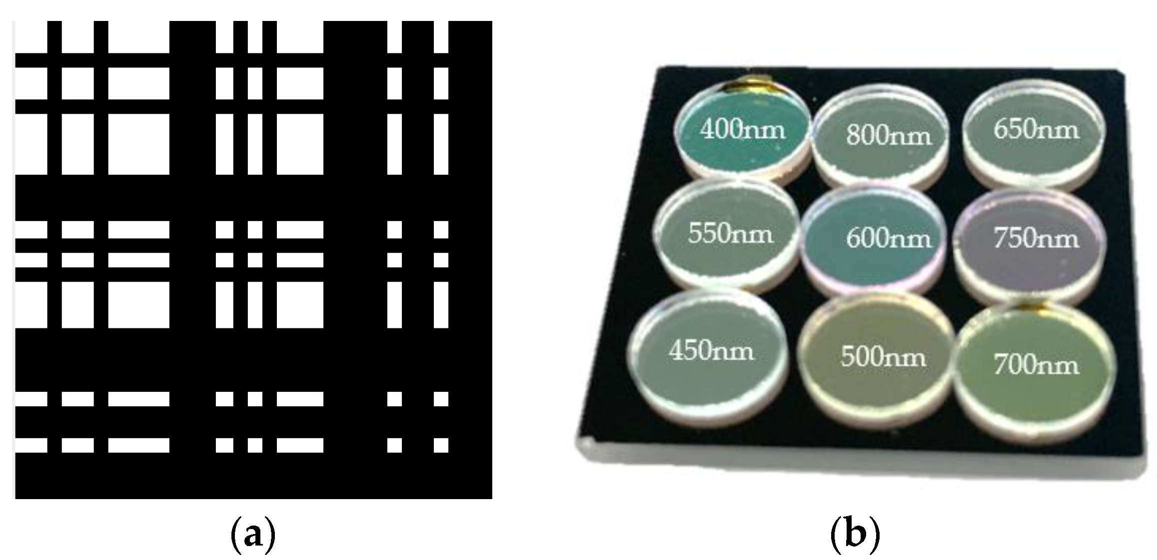
3.1. Prototype
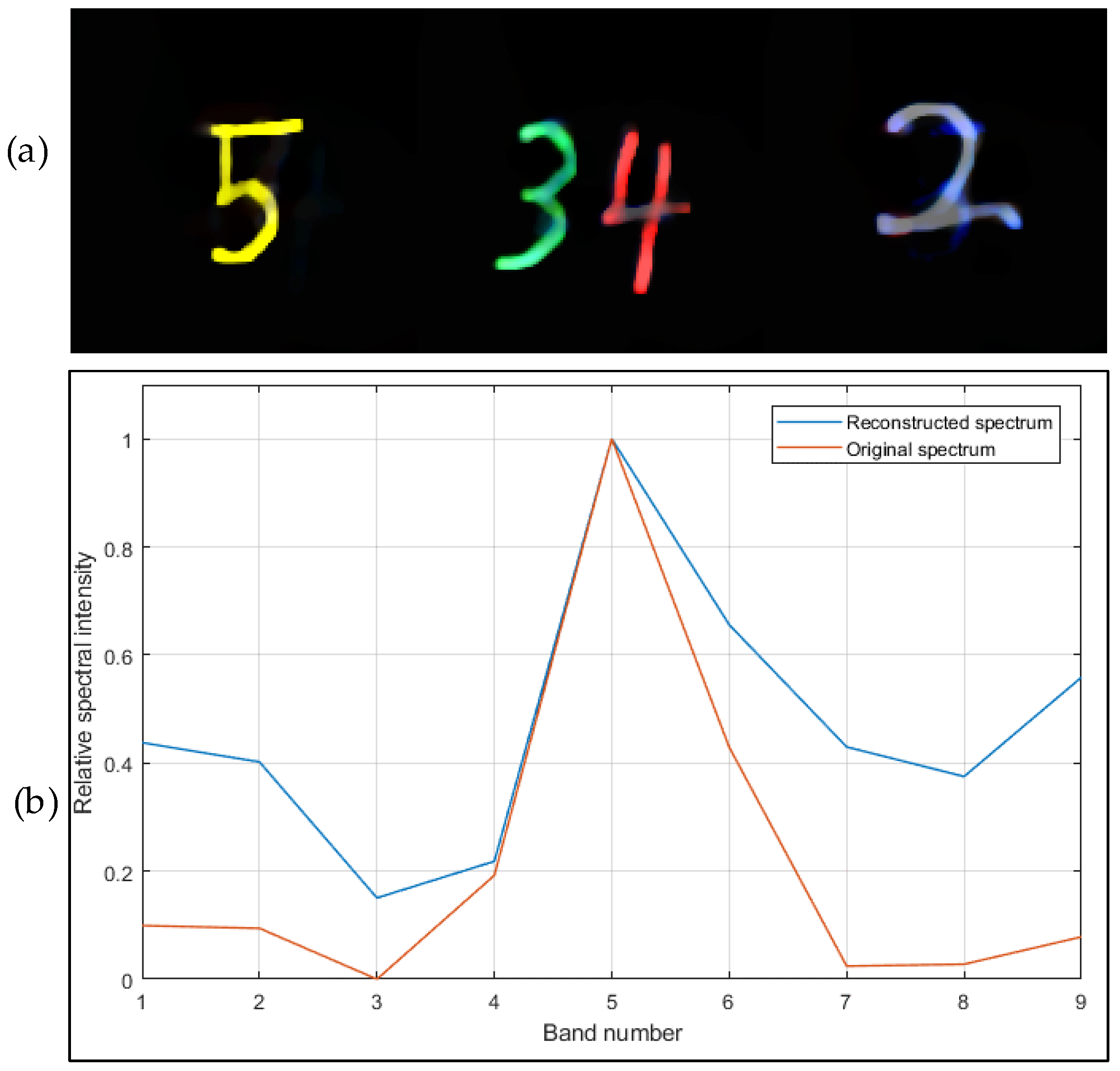
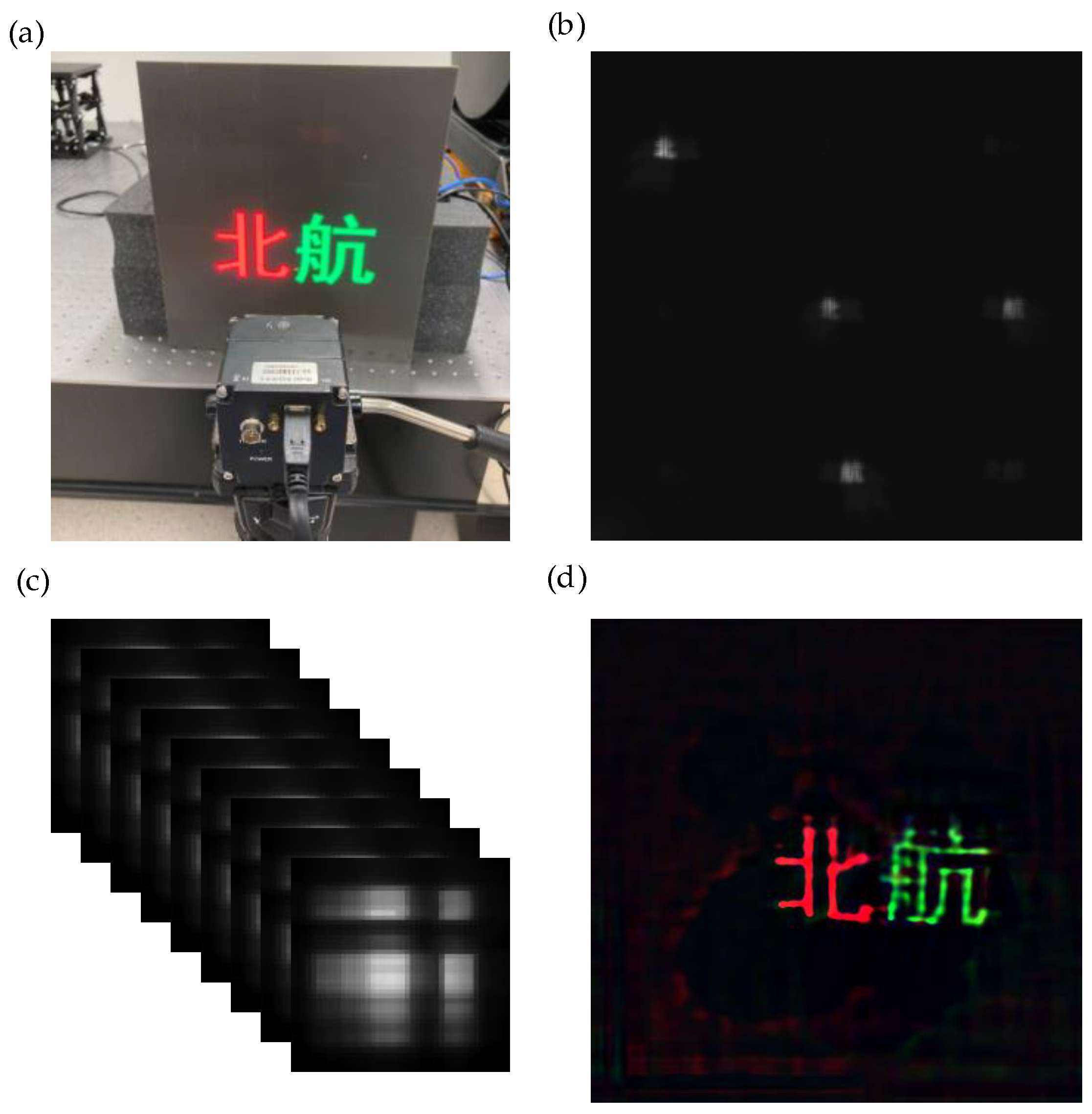
3.2. Imaging Result
4. Discussion
Author Contributions
Funding
Institutional Review Board Statement
Informed Consent Statement
Data Availability Statement
Conflicts of Interest
References
- Landgrebe, D. Hyperspectral image data analysis. IEEE Signal Process. Mag. 2002, 19, 17–28. [Google Scholar] [CrossRef]
- Gowen, A.A.; O’Donnell, C.P.; Cullen, P.J.; Downey, G.; Frias, J.M. Hyperspectral imaging—An emerging process analytical tool for food quality and safety control. Trends Food Sci. Technol. 2007, 18, 590–598. [Google Scholar] [CrossRef]
- Shaw, G.A.; Burke, H.-h.K. Spectral Imaging for remote sensing. Linc. Lab. J. 2003, 14, 3–24. [Google Scholar]
- Murakami, Y.; Obi, T.; Yamaguchi, M.; Ohyama, N.; Komiya, Y. Spectral reflectance estimation from multi-band image using color chart. Opt. Commun. 2001, 188, 47–54. [Google Scholar] [CrossRef]
- Kerekes, J.P. Hyperspectral remote sensing subpixel object detection performance. In Proceedings of the 2011 IEEE Applied Imagery Pattern Recognition Workshop (AIPR), Washington, DC, USA, 11–13 October 2011; pp. 1–4. [Google Scholar]
- Ackerman, S.; Strabala, K.I.; Menzel, W.P.; Frey, R.A.; Moeller, C.C.; Gumley, L.E. Discriminating clear sky from clouds with MODIS. J. Geophys. Res. Space Phys. 1998, 103, 32141–32157. [Google Scholar] [CrossRef]
- Lemmon, M.; Smith, P.; Shinohara, C.; Tanner, R.; Woida, P.; Shaw, A.; Hughes, J.; Reynolds, R.; Woida, R.; Penegor, J.; et al. The Phoenix Surface Stereo Imager (SSI) Investigation. In Proceedings of the Lunar and Planetary Science XXXIX, League City, TX, USA, 10–14 March 2008; p. 2156. [Google Scholar]
- Deng, L.; Mao, Z.; Li, X.; Hu, Z.; Duan, F.; Yan, Y. UAV-based multispectral remote sensing for precision agriculture: A comparison between different cameras. ISPRS J. Photogramm. Remote Sens. 2018, 146, 124–136. [Google Scholar] [CrossRef]
- Zhang, Y.; Su, Z.; Shen, W.; Jia, R.; Luan, J. Remote Monitoring of Heading Rice Growing and Nitrogen Content Based on UAV Images. Int. J. Smart Home 2016, 10, 103–114. [Google Scholar] [CrossRef]
- Guyon, D.; Bréda, N. Applications of Multispectral Optical Satellite Imaging in Forestry. In Land Surface Remote Sensing in Agriculture and Forest; Baghdadi, N., Zribi, M., Eds.; Elsevier: Amsterdam, The Netherlands, 2016; pp. 249–329. [Google Scholar]
- Suneetha, M.; Boggavarapu, L.; Vaddi, R.; Raja, A.R.; Gopalakrishnan, R.; Jha, C.S. Object based Classification of Multispectral Remote Sensing Images for Forestry Applications. In Proceedings of the 2020 3rd International Conference on Image and Graphics Processing, Singapore, 8–10 February 2020; Association for Computing Machinery: Singapore, 2020; pp. 153–157. [Google Scholar]
- Umar, M.; Rhoads, B.L.; Greenberg, J.A. Use of multispectral satellite remote sensing to assess mixing of suspended sediment downstream of large river confluences. J. Hydrol. 2018, 556, 325–338. [Google Scholar] [CrossRef]
- Xiao, P.; Feng, X.; An, R.; Zhao, S. Segmentation of multispectral high-resolution satellite imagery using log Gabor filters. Int. J. Remote Sens. 2010, 31, 1427–1439. [Google Scholar] [CrossRef]
- Carlotto, M.J.; Lazaroff, M.B.; Brennan, M.W. Multispectral image processing for environmental monitoring. Appl. Opt. Sci. Eng. 1993, 1819, 113–124. [Google Scholar] [CrossRef]
- De Biasio, M.; Arnold, T.; Leitner, R.; Mcgunnigle, G.; Meester, R. UAV-based environmental monitoring using multi-spectral imaging. In Airborne Intelligence, Surveillance, Reconnaissance (ISR) Systems and Applications VII, Proceedings of the SPIE Defense, Security, and Sensing, Orlando, FL, USA, 5–9 February 2010; International Society for Optics and Photonicsm: Bellingham, WA, USA, 2010; Volume 7668, p. 766811. [Google Scholar] [CrossRef]
- Elmasry, G.; Mandour, N.; Al-Rejaie, S.; Belin, E.; Rousseau, D. Recent Applications of Multispectral Imaging in Seed Phenotyping and Quality Monitoring—An Overview. Sensors 2019, 19, 1090. [Google Scholar] [CrossRef] [Green Version]
- Skauli, T.; Torkildsen, H.E.; Nicolas, S.; Opsahl, T.; Haavardsholm, T.; Kåsen, I.; Rognmo, A. Compact camera for multispectral and conventional imaging based on patterned filters. Appl. Opt. 2014, 53, C64–C71. [Google Scholar] [CrossRef]
- Schmitt, F.J.M.; Hardeberg, J.Y.; Brettel, H. Multispectral color image capture using a liquid crystal tunable filter. Opt. Eng. 2002, 41, 2532–2549. [Google Scholar] [CrossRef]
- Tominaga, S. Spectral imaging by a multichannel camera. J. Electron. Imaging 1998, 3648, 332–341. [Google Scholar] [CrossRef]
- Kanaev, A.V.; Kutteruf, M.R.; Yetzbacher, M.K.; DePrenger, M.J.; Novak, K.M. Imaging with multi-spectral mosaic-array cameras. Appl. Opt. 2015, 54, F149–F157. [Google Scholar] [CrossRef] [PubMed]
- Zhao, Y.; Yue, T.; Chen, L.; Wang, H.; Ma, Z.; Brady, D.J.; Cao, X. Heterogeneous camera array for multispectral light field imaging. Opt. Express 2017, 25, 14008–14022. [Google Scholar] [CrossRef]
- Fenimore, E.E.; Cannon, T.M. Coded aperture imaging with uniformly redundant arrays. Appl. Opt. 1978, 17, 337–347. [Google Scholar] [CrossRef]
- DeWeert, M.J.; Farm, B.P. Lensless coded-aperture imaging with separable Doubly-Toeplitz masks. Opt. Eng. 2015, 54, 023102. [Google Scholar] [CrossRef] [Green Version]
- Monakhova, K.; Yanny, K.; Aggarwal, N.; Waller, L. Spectral DiffuserCam: Lensless snapshot hyperspectral imaging with a spectral filter array. Optica 2020, 7, 1298. [Google Scholar] [CrossRef]
- Asif, M.S.; Ayremlou, A.; Veeraraghavan, A.; Baraniuk, R.; Sankaranarayanan, A. FlatCam: Replacing Lenses with Masks and Computation. In Proceedings of the IEEE International Conference on Computer Vision Workshop (ICCVW), Santiago, Chile, 7–13 December 2015; pp. 663–666. [Google Scholar] [CrossRef]
- Antipa, N.; Kuo, G.; Heckel, R.; Mildenhall, B.; Bostan, E.; Ng, R.; Waller, L. DiffuserCam: Lensless single-exposure 3D imaging. Optica 2018, 5, 1–9. [Google Scholar] [CrossRef]
- Adams, J.K.; Boominathan, V.; Avants, B.W.; Vercosa, D.G.; Ye, F.; Baraniuk, R.G.; Robinson, J.T.; Veeraraghavan, A. Single-frame 3D fluorescence microscopy with ultraminiature lensless FlatScope. Sci. Adv. 2017, 3, e1701548. [Google Scholar] [CrossRef] [Green Version]
- Liang, J. Punching holes in light: Recent progress in single-shot coded-aperture optical imaging. Rep. Prog. Phys. Soc. 2020, 83, 116101. [Google Scholar] [CrossRef] [PubMed]
- Jalali, S.; Yuan, X. Snapshot Compressed Sensing: Performance Bounds and Algorithms. IEEE Trans. Inf. Theory 2019, 65, 8005–8024. [Google Scholar] [CrossRef] [Green Version]
- Yuan, X.; Brady, D.J.; Katsaggelos, A.K. Snapshot Compressive Imaging: Theory, Algorithms, and Applications. IEEE Signal Process. Mag. 2021, 38, 65–88. [Google Scholar] [CrossRef]
- Kwan, C.; Gribben, D.; Chou, B.; Budavari, B.; Larkin, J.; Rangamani, A.; Tran, T.; Zhang, J.; Etienne-Cummings, R. Real-Time and Deep Learning Based Vehicle Detection and Classification Using Pixel-Wise Code Exposure Measurements. Electronics 2020, 9, 1014. [Google Scholar] [CrossRef]
- Zhang, J.; Xiong, T.; Tran, T.; Chin, S.; Etienne-Cummings, R. Compact all-CMOS spatiotemporal compressive sensing video camera with pixel-wise coded exposure. Opt. Express 2016, 24, 9013–9024. [Google Scholar] [CrossRef]


Publisher’s Note: MDPI stays neutral with regard to jurisdictional claims in published maps and institutional affiliations. |
© 2021 by the authors. Licensee MDPI, Basel, Switzerland. This article is an open access article distributed under the terms and conditions of the Creative Commons Attribution (CC BY) license (https://creativecommons.org/licenses/by/4.0/).
Share and Cite
Wang, J.; Zhao, Y. Lensless Multispectral Camera Based on a Coded Aperture Array. Sensors 2021, 21, 7757. https://doi.org/10.3390/s21227757
Wang J, Zhao Y. Lensless Multispectral Camera Based on a Coded Aperture Array. Sensors. 2021; 21(22):7757. https://doi.org/10.3390/s21227757
Chicago/Turabian StyleWang, Jianwei, and Yan Zhao. 2021. "Lensless Multispectral Camera Based on a Coded Aperture Array" Sensors 21, no. 22: 7757. https://doi.org/10.3390/s21227757
APA StyleWang, J., & Zhao, Y. (2021). Lensless Multispectral Camera Based on a Coded Aperture Array. Sensors, 21(22), 7757. https://doi.org/10.3390/s21227757