1. Introduction
High-precision machining requires significant contributions to limit inertial disturbances and to reduce vibrational problems. To satisfy the industrial demand, several mechanisms have been developed with two main different configurations: parallel kinematic machines (PKMs) and serial kinematic machines (SKMs). Due to the reduction of moving masses, system compactness, increased load capacity, and higher stiffness, PKMs present an enhanced solution for a prescribed level of accuracy and dexterity.
A parallel architecture is a closed loop mechanism based on a moving frame linked to a static frame by a set of kinematics modules or legs [
1]. However, the closed loop architecture and the kinematic constraints limit the workspace of PKMs; defined as the set of poses obtained by the joints’ configurations.
In the literature, these limitations are studied to satisfy the high-precision machining requirements with the focus on fixturing elements. Industrial awareness estimates that 40% of rejected products are associated to the fixture design [
2], proving its importance. Consequently, the scientific community proposed several strategies and procedures to evaluate the performance of a fixture based on motion accuracy, workpiece-stability, workpiece-deformation, low set up time, and system adaptability [
3,
4].
A fixture is a mechatronic system applied to guarantee an accurate workpiece location within the workspace, rigidly holding and supporting it to the machining loads, influencing its static and dynamic performance. Fixtures can be classified into three groups: locators, supports and clampers [
5]. These are detailed as follows:
- -
Locators are devoted to correctly positioning the workpiece in 3D space;
- -
Supports enable the workpiece-static load-reaction without any location or positioning function;
- -
Clampers provide the force to maintain the workpiece position and orientation in their initial setting avoiding the time-dependent deformation or distortion [
6,
7,
8];
- -
In addition, the closed loop fixtures perform two important functions:
- -
Workpiece location: to locate and place the part in the workspace;
- -
Disturbance suppression: to maintain the workpiece in a predefined position and reject any manufacturing forces or external perturbation;
Vibrations in industrial machining applications are generated by internal and external disturbances, with a significant effect on equipment reliability and product quality. Moreover, the disturbance presence and the high-magnitude oscillation of the workpiece may result in its damage and breakage. Piezoelectric elements (PZT) have become an attractive solution for vibration reduction due to their significant electro-mechanical connection, the high-frequency response, and superior durability [
9,
10]. In order to reduce the existing vibrations of a precision machining with PZT modules, many control approaches are recommended to address the limitations produced by undefined dynamics, complex boundary settings, non-linear configuration, and the electrical saturation of the actuators [
11].
Recent research focused on the use of flexure-based mechanisms. These elements have several advantages as negligible friction, minor backlash, and no-hysteresis [
11]. Consequently, flexure-based devices driven by PZT-actuators represent the optimal arrangement for high-precision machining [
11,
12], as such actuators can generate continuous extension and backward movements with high-resolution, high-stiffness, and high-driving force within an extended-response range.
Several control approaches including robust control, adaptive control and neural network control have been developed and investigated [
13,
14,
15] to improve the dynamic performance and managing the PZT non-linearities. Authors concentrate the proposed research in thin-wall machining applications. The literature presents different solutions to apply actuators and control strategies to contain the vibrations in thin-walled machining [
16,
17,
18]. Active dampers are one of the main solutions applied for reduce vibration contribution in variable machining conditions. In this way, an interesting study was proposed by Yang et al. [
19] that designed an active and lightweight device based on eddy current damping (EDC) to attenuate the vibrations produced during the machining of a thin-walled aluminum frame. Based on the electromagnetic induction, the authors achieved a reduction of the machining vibrations of up to 84%. An alternative approach was presented by Wang et al. [
20] with an active milling vibration control system based on a time-space varying proportional derivative (PD) which varies the regulator parameters according to the position of the milling point. The system used a piezoelectric patch as an actuator to suppress the vibration of the thin-wall workpiece milling. Despite obtaining higher control capabilities with respect to the standard PD, the simulation and validation was carried out for a known path with a rectangular thin-wall workpiece. An alternative variable PD controller was implemented in [
21] with a fuzzy inference model based on the ANFIS system, proving its capabilities for thin-walled milling parts model. Furthermore, this kind of application is based on the flexible beam active vibration control basis [
22,
23,
24]. The main issues are related to the actuator positioning (workpiece dependent) and the limitation upon the machining of the corresponding surface.
In order to overcome these problems, the active holders are studied, as in Diez et al. [
25], where the authors employed a compliant piezo-actuated flexure to compensate the deformations of the workpiece, improving the final dimensional error from 246.0 µm to 36.0 µm. The compensation system considered the static deformations experienced in machining comprising of low-rigidity parts. The control system is based on a reference model that runs in real time which is a good procedure to compensate for dimensional errors due to part deformation in milling machining. A similar unidirectional controlled structure was presented in [
26] based on a piezo stack actuator and a property support base designed with proper flexure hinges to allow the compensation of the workpiece machining disturbances. Despite the good results, the control system was based on an analytical model to estimate the force and consequently the workpiece is dependent. Moreover, the dynamometer requested as feedback for the regulator tends to be difficult to install and limits the dimensions of the machinable workpieces. However, the authors managed to obtain an industrially appliable device by creating the corresponding supports upon the given sensor. Further configurations were based on a two-directional active piezo-based workpiece holder as the flexure-based system in [
27] where the authors employed a linear motor for the large motion and a piezoelectric actuator for the fine stage positioning obtaining a reduction in the maximum tracking error of 83% for a sinusoidal profile machining test. Similarly, in [
28,
29,
30] the authors presented different piezoelectric based moveable frame obtained through flexure hinges and springs. An adaptive application based on the filtered-X LMS algorithm was applied by Rashid and Nicolescu [
31] to improve the dynamics of the fixture system by eliminating the vibration signal generated by the cutting process, succeeding in improving surface quality and tool life. The study reports a test with simple geometry affected by a forces profile lower than 800 N amplitude, with a frequency range under investigation lower than 250 Hz. The campaign outcomes were satisfying with a Rz lower than 3.8 µm. A different holder was implemented in [
32] for variations of ±50 μm and forces up to 2500 N, the control was based on a relative positioning error between the tool and the machine table. To improve the system capabilities, an optimal LQG (linear quadratic gaussian) controller was implemented by Parus et al. [
33] for an active clamping system based on piezoelectric actuators. The system suppresses the vibrations through the forces acting on the workpiece table independently of the vibration nature and level. An LQG controller was employed with a Kalman filter in [
34] to actively introduce damping into the system with a high-voltage piezoelectric actuator, equipped with a thermal management system required for long-term operations, and a laser sensor. The results showed an increment capability in the depth of cut from 0.6 mm up to 2.3 mm for a spindle speed of 240 RPM. In a similar approach, in [
35] the authors employed a laser sensor for a runout control based on a piezoelectric actuator. The sensor chosen for the feedback signal, a laser vibrometer, despite providing an accurate vibration measurement, it has several disadvantages based on the measurement method, for example, it cannot be used when a coolant is applied. Differently, an artificial neural network-based controller was implemented in [
36], that was used to determine the chatter frequencies and remaining vibration amplitudes that were further optimized by a genetic algorithm approach. Nevertheless, the approach requires an initial training phase and optimization.
Although the literature presents various vibration control methods and significant achievements are demonstrated, further studies are required to investigate the vibration compensation in broadband frequency range in combination with precise workpiece positioning.
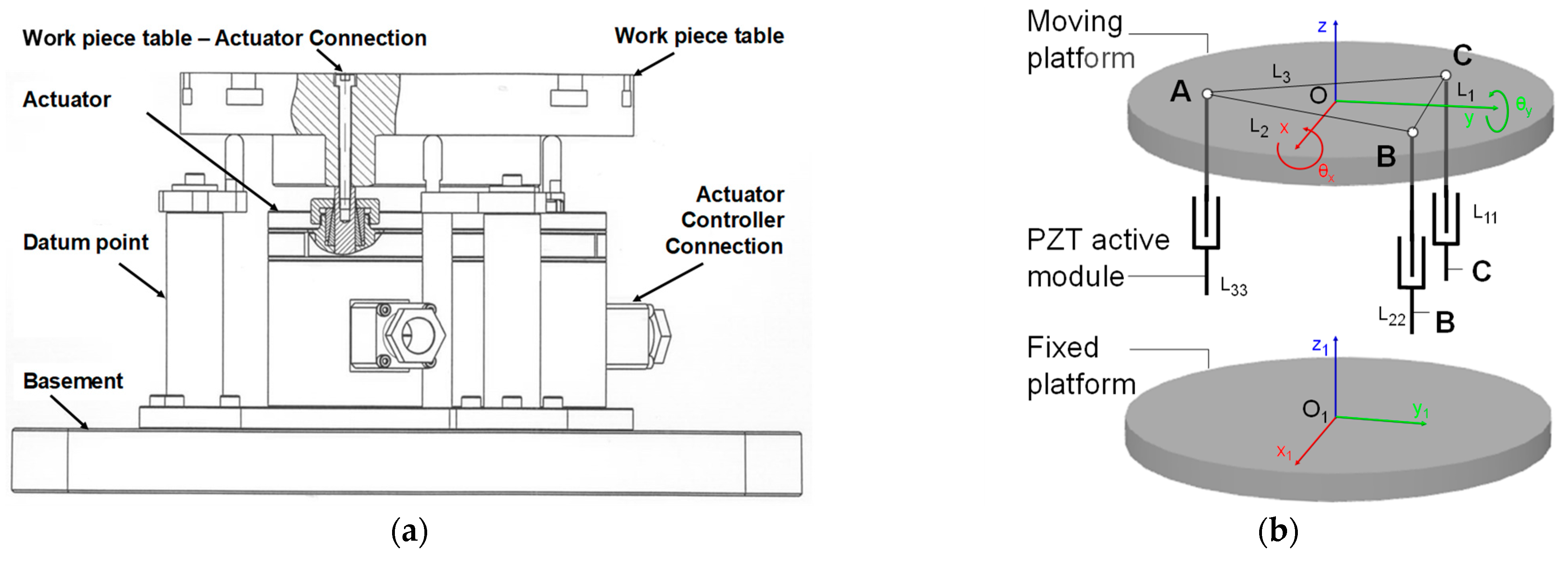
The main contribution of this paper is to extend and validate a compact fixture system that regulates in real-time a set of piezo-actuated modules in an industrial environment. Authors propose a platform based on a 3-DoF (degrees of freedom) structure, established on the Kutzbach Grubler equation as described in [
8], driven by preloaded piezo-stack actuators that act on the vertical axis at different table points.
Figure 1a presents the developed prototype, in
Figure 1b the schematic diagram of the active platform is shown.
Figure 1c,d show two different poses within the tolerable workspace.
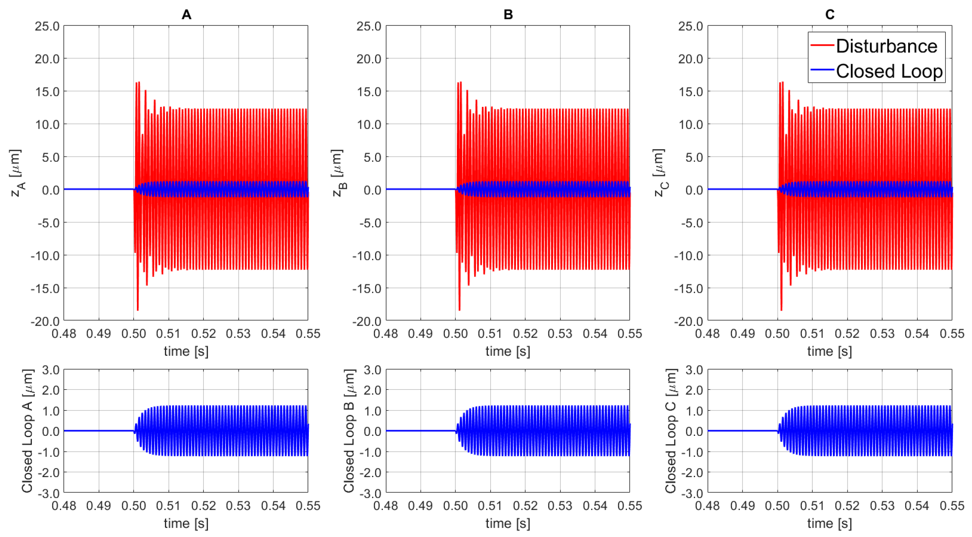
The platform’s coupling effect is generated by the actuated leg that exerts a disturbance on the other legs through the moving frame motion. The effect can be investigated with a sequence of pose tests based on step signals as target input. The experimental campaign results of the original platform on a given commercial machine tool [
8] are shown in
Figure 2. A step input is given on module A, and the corresponding coupling is measured for modules B and C. In the prior work, the scope was limited to clamping recovery (low-frequency disturbances) and the implemented regulator was developed for a quasi-static application. The actual coupling effect presented in
Figure 2 for a 20 µm input on module A causes a peak deviation of ±4.02 μm for both B and C modules. This undesirable effect is a main challenge that needs to be solved to allow the vibration rejection function for the micro-positioning platform.
The additional contribution of this paper is to progress the design developed in [
7] by implementing a dynamic regulator to allow disturbance rejection capabilities and to contain the flexure-based coupling effects in thin-plate precise machining. This is achieved by a suitable selection of the control algorithm and a gain-scheduling approach. The proposed method uses a bumpless switching controller and a fine-tuning procedure to estimate the parameter uncertainty and enable the external disturbance containment in an extended broad-band frequency range. The platform and the actuator controllers are designed based on a gain scheduling PID (proportional integral derivative), in standard ISA form, to guarantee the stability [
37,
38,
39,
40,
41]. The accuracy is proved through a set of simulations and experimental comparisons, performed on a proposed model, for the two objective functions: set-point tracking and disturbance rejection.
2. The Concept and Formulation of 3-DoF PKM Piezo-Actuated Platform: Kinematics and Dynamics
In a three-dimensional workspace, a rigid body requires the support of 3 constrained points to guarantee the location’s definition; this postulate is the base of the 3-DoF parallel mechanism design. The proposed active PKM system, shown in
Figure 3a, is composed of a top moving table, a fixed base platform, three (prismatic joint-spherical joint-prismatic joint) PSP active legs r
i (i = 1, 2, 3) and three datum points for supporting pillars with no actuation. Each PZT-module, installed between the basement and the workpiece table, contains a piezoelectric controlled actuator that provides proper forces, damping capacity, and high stiffness. Due to its electromechanical property, the piezoelectric elements are affected by hysteresis, and this may be minimized by using an inner closed loop regulator, which can compensate the parasitic error in the active mechanism. In order to overcome these motion problems, three precision capacitive sensors are used in the table to measure the contribution of each actuator and the moving platform, forming the final closed loop system [
11,
42,
43]. The PZT-actuator selected for this active fixture platform is the PST 1000/25/40 VS35, which has a maximum stroke capability of 40 µm, it has an axial stiffness of 450 N/µm, and a blocking force of 25.0 kN. The piezoelectric modules are fixed on the base frame and placed on a circumference, at equal angular distance between each other, around the center of the moving frame; and are attached to the latter through a rigid connector. The PKM platform is represented by a MIMO (multiple input multiple output) system or it could be synthetized by three parallel SISO (single input single output) subsystems. The moving frame can move forward-backward (maximum 40.0 μm stroke) on a torsional-flexure mechanism in accordance to a digital input signal along the vertical-axis (compliant direction) for the SISO module. The selected high-precision capacitive sensor has a resolution of 7.3 nm considering an operative range of 100.0 μm with a response-band of 0–17.5 kHz. A PZT-amplifier controlled by a digital computer board (dSPACE-1104), with an output peak voltage of 5.0 V, is adopted to generate the control voltage for the piezoelectric actuator motions, and the piezoelectric amplifier component corresponds to the SVR1500, with an amplification factor of 100.0 ± 0.1. Finally, a personal computer is used to run the MATLAB-Simulink control, the GUI user-interface, and to supervise the control functions.
To describe the platform motion, two coordinate frames are defined; one local O-XYZ is positioned on the moving frame and one global O
1-X
1Y
1Z
1 is fixed on the ground, as shown in
Figure 3b. The coordinate frames are aligned along the
z-axis and present the same orientation when the moving workpiece table is in its initial position.
The control presented in this paper acts on [
z;
θx;
θy] directions which are defined with respect to the center-of-mass of the workpiece table. The direction z represents the vertical movement aligned to the
z-axis,
θx is the rotation about the
x-axis, and
θy is the rotation about the
y-axis. Considering the moving platform as a rigid element, the motion parameters ([
z;
θx;
θy]) can be allocated among points A, B, and C, which compose an equilateral triangle (ΔABC) on the mobile platform with side length L. Point O corresponds to the center of the circumscribed circle of ΔABC. The
y-axis is positioned at the middle of the CB segment between the two passive spherical joints; moreover, the
z-axis corresponds to the normal vector of the top moving frame; finally, the
x-axis can be identified through the right-hand rule. The vertical and tilt-tip motions of the reference point O can be obtained through the following Equations (1)–(3):
where I is the input vector, corresponding to the displacements of the three PZTs; and
J0 is the transformation matrix from I to O, which is a function of the circumference containing ΔABC radius (R).
The dynamic differential equation of the active piezoelectric platform motion in
Figure 4 can be described, using the Newton’s second law of motion, by the following Equation (4):
where
M,
C,
K, and d correspond to the mass matrix, the modal damping matrix, the stiffness matrix and the displacement vector, respectively; the factor
F describes the resultant external forces applied to the corresponding rigid-mass;
B is the force/voltage transformation; and
V corresponds to the input voltage of PZT module. The model parameters
M,
C, and
K were analytically estimated with the finite element (FE) analysis, as presented in [
7]. The ground frame position is denoted as
= [
z0;
θx,0;
θy,0], the moveable frame position as
= [
z1;
θx,1;
θy, 1], and the actuator voltages as
= [
VA;
VB;
VC]. These coordinates are chosen based on the vertical actuator forces and the vertical measurements configuration, as represented in Equation (5):
In Equation (5), a0,j and a1,j, denote, respectively, the ground frame’s and moving platform’s positions, where j corresponds to the jth PZT element. Moreover, the sensors assessing a0,1, a0,2, and a0,3 are intended as perfectly collocated. Finally, the actuators forces are stated by uj, and B, R0, R1 in ℝ3×3 represent the static transformation matrices.
The initial structure’s model is presented in
Figure 4a, where the connection mechanism is denoted by the K
c stiffness positioned upon the PZT actuator (K
pzt, C, F
pzt). The chosen scheme created an internal displacement variation caused by the stiffness in series to the PZT model, which increased the complexity of the final system. Considering that K
c was high, the model was simplified into the second scheme shown in
Figure 4b, where the actual stiffness of the system is kept unchanged but the inner displacement, represented by
apzt in
Figure 4a, is neglected.
In order to validate the simplified model, a modal comparison scheme was performed, by evaluating the input forces (A, B, and C channels) for each active module with the corresponding displacements ([
z;
θx;
θy]). The results are summarized in
Figure 5, where a single SISO model outcome is shown, representative of all the SISO tests. The difference between the architecture with interface node (
Figure 4a) and the simplified scheme (
Figure 4b) is lower than 4.93 dB. The results confirm the implementation of the second scheme without affecting the overall performance. Nevertheless, this simplification error was taken into account when the control tuning was carried out, by implementing a final regulator with higher robustness. Finally, it is worth mentioning that based on the specific reference frame selected, the
θy rotation is null for the input force A as it is positioned along the y axis, as shown in
Figure 3b.
The Modelling of the Piezo Actuator
The piezoelectric stack actuator model is described by a linear system, as stated in Equations (6) and (7). The hysteresis effect is neglected, and the polarization direction is selected along the body stack in vertical axis [
44,
45]. The piezoelectric stack actuator can be written as:
where
S3 is the mechanical strain,
D3 is the electric displacement,
E3 is the electric field,
T3 is the mechanical stress,
d33 is the piezoelectric constant,
sE33 is the elastic compliance at constant field
E, and
T33 corresponds to the permittivity at constant stress
T. According to the assumption that each layer has a thickness
h, a cross-sectional area
A, and the electrical potential between the two phases of each layer is
dV, the following equations are obtained:
Furthermore, as in [
46,
47] the displacement of each layer,
, can be formulated as:
Considering a PZT with
n layers, with identical polarized direction and stack form, the resulting final displacement,
, can be computed as:
where
is the equivalent stiffness, denoted as
Km. Finally, in order to obtain the voltage-force function, Equation (11) is rewritten as:
5. Tracking Performance under Continuously Varying Disturbances
Experimental tests are conducted to verify the developed model and to establish performance measurements for the piezo-driven flexure-based mechanism. Testing campaigns were performed on a vertical milling machine with a 2.50 mm diameter and a two-teeth tool to study the machining disturbances behaviour. The workpiece material was a thin-wall component made in high-grade carbon steel. From these experimental tests, a model for the disturbance signal was obtained. The machining disturbance signal (d) can be represented as an unknown deterministic signal with the following mathematical formulation:
where
represents the amplitudes,
the frequencies, and
the phases. Finally, a random variable signal is added. For this application, it can be defined as sudden load changes that could physically represent the tool breakages or the tool first contact with the workpiece. The step disturbance signals selection of ±2000 N is due to the evaluation of edge capabilities of the developed PKM platform.
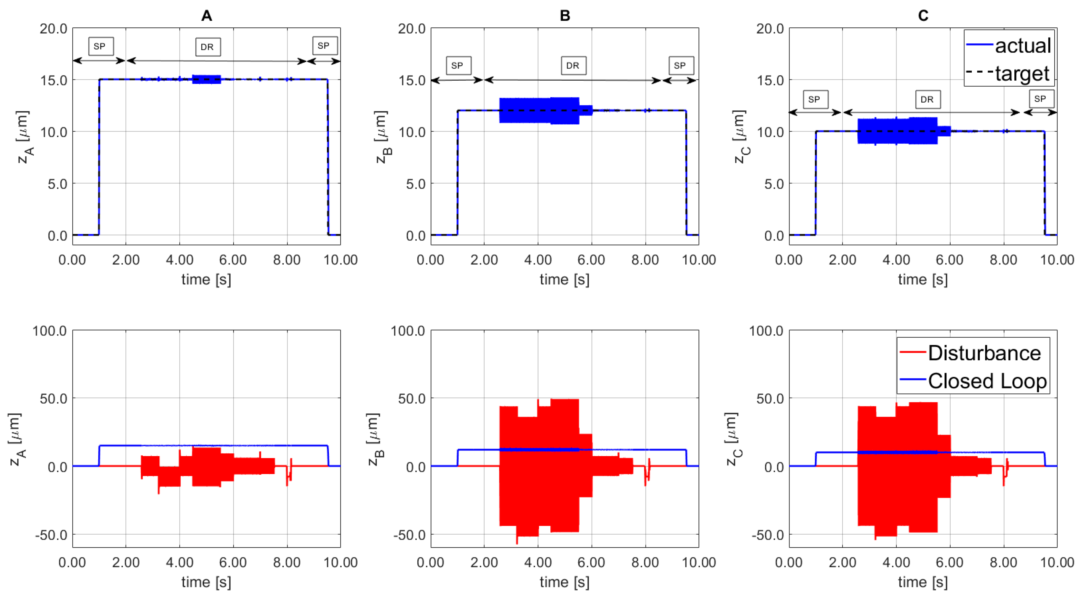
In the simulated tests, the PKM platform was arranged with a defined position and orientation determined by the following three displacement signals: SISOA as 15 μm, SISOB as 12.0 μm, and SISOC equal to 10 μm; which in terms of platform motion corresponds to z = 12.33 µm, , and .
During the initial tracking phase, the set point (SP) tuning is used. After 1.50 s a cutting machining disturbance is simulated, according to Equation (14), and thus the tuning is changed to disturbance rejection (DR). The disturbance was stopped at 8.50 s, where the SP tuning was implemented to transport the platform to the initial setting position/orientation, home position. During the 7.0 s disturbance interval, several sinewaves were implemented, from 50 Hz to 1500 Hz with various phases and amplitudes, from 375 N to over 1500 N. The results are shown in
Figure 14 where the top Figures represent the tracking signals for each line.
Figure 14—bottom side, shows the disturbance signal d (solid red line) and the resulting signal from the PKM platform (solid blue line). The residual vibration remained within the threshold error specified for thin-wall machining application.
The system confirms a containment greater than the 95% of the 1.5 kN amplitude disturbances with the chosen tuning parameters. A step disturbance for both positive and negative directions is applied at 8.0 s and the system demonstrates the ability to suppress the perturbation, that in industrial setting could damage the PZT actuator. The frequency variability of the selected disturbances does not affect the regulation performance, the proposed architecture demonstrates the promising findings.
6. Conclusions
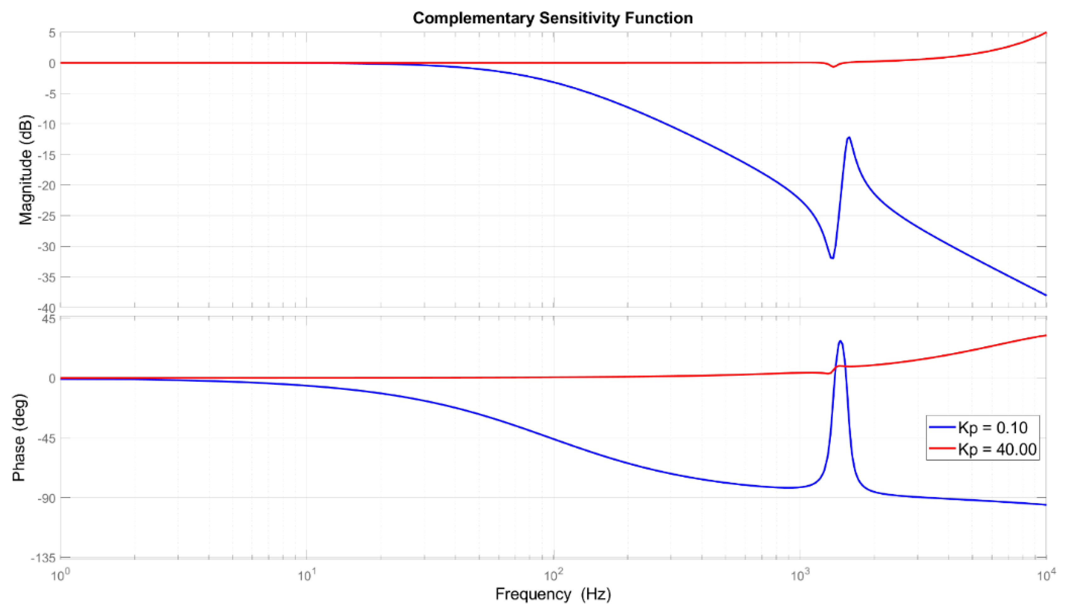
A 3-DoF compact parallel platform with a vertical motion and two rotations was used to demonstrate the extension of fixturing system functions as micro-positioning and vibration rejection in machining application. The PKM mechanism includes the bottom fixed frame, three piezoelectric actuators, three capacitive sensors, three datum point passive pillars, the top frame, and the flexures that perform the motions. The platform and the piezo-actuator elements were analyzed and modeled to describe the static and dynamic performance of the motion system. The controller was established for the MIMO (multiple input multiple output) system, using the collocated measured position signal as feedback input for each loop. The control structure corresponds to a PID in standard ISA form with a gain scheduling scheme. The actuator coupling effect was reduced with a maximum displacement of ±0.59 µm and a recovering time lower than 8.9 ms as response to a 20.0 µm tracking. The regulator robustness was increased during the disturbance rejection, and it has expanded the set-point following frequency range of the PZT platform, obtaining a final broadband rejection capability up to 1.5 kHz. The final parameters, tuned based on both the sensitivity and complementary sensitivity functions, obtained a final containment as 50 dB at 300 Hz and 20 dB at high frequency (1.3 kHz). To effectively verify the proposed approach, simulations and real-time experiments were carried out. The sensitivity analysis, the tracking results, and the disturbance rejection outcomes confirm the compliance of the simulation models. In the experimental case study, the signals were generated based on a model obtained from extracted data during machining and used to test the disturbance rejection platform capabilities. The tests were carried out within the platform workspace of: z = ±20 µm, αx = ±427.67 µrad, and αy = ±493.83 µrad. Furthermore, sudden load profiles were applied to the PKM platform with different amplitudes, from 375 N to 1500 N, variable phases and multi-tone frequencies close to critical resonances. The system confirms a containment greater than the 96% of disturbances with the chosen tuning parameters. Future work will focus on noise reduction, sensor precision, and measurement techniques to improve the robustness of the proposed feedback control approach.


