1. Introduction
As the application field of radar systems has expanded, the number of radar sensors operating at the same frequency has been continuously increasing. Moreover, the use of the multiple-input multiple-output (MIMO) method can efficiently increase radar performance by sharing the same frequency band. There have been many studies on MIMO performance in recent years [
1,
2,
3,
4]. MIMO radars can be used to increase the virtual antenna size, which improves the angular resolution through coherent processing [
5], or be used in a bistatic manner that is transmitted and received from different sites [
6].
Multiple transmission methods in MIMO radar include the array-space multiple transmission method that transmits different waveforms from different arrays and synthesizes them in the receiver, and the beam-space multiple transmission method that transmits different waveforms in different directions. In all cases, because the different transmit waveforms should be received independently in the receiver, it is necessary to use signals with orthogonal characteristics. Unfortunately, because the delay of the reflective signal is specified by the target position and cannot be synchronized from the receiver in radar systems, transmit waveforms should be orthogonal for all time delays, which is almost impossible. Therefore, the transmit waveforms in MIMO radar are usually designed to minimize the cross-correlation for all time delays—called a quasi-orthogonal waveform—while minimizing the sidelobe level of the autocorrelation to improve detection performance.
Orthogonality, which removes other waveforms, is achieved by dividing the power of each waveform into the different domains rather than cancelling them. The typical methods for designing orthogonal waveforms are time division multiplexing (TDM), frequency division multiplexing (FDM), and code division multiplexing (CDM) [
7,
8,
9]. Although the TDM method has perfect orthogonal characteristics, it has low time (i.e., energy) efficiency and may require additional processing for a moving target because the measurements are not performed simultaneously. The FDM method also has perfect orthogonal characteristics but has low spectral efficiency, and range-angle coupling occurs because of the linear relationship between the frequency and the index of the antenna element. For CDM, especially in radar systems, it is difficult to find a perfect orthogonal waveform or code domain for all delay times, as mentioned above. This paper proposes a method for dividing range bins using different pulse repetition frequencies (PRFs) for pulse doppler radars.
The signal processing of the pulse doppler radar consists of a matched filter for intra-pulse modulation and coherent integration between pulses. If the received pulse is modulated by different codes, the output of the matched filter is the sum of correlations between the matched and mismatched codes. In this first step, the signal-to-interference ratio (SIR) is improved in terms of both noise and cross-correlations, constituting the interference signal. However, because the interpulse coherency is maintained even for the mismatched codes, interference by cross-correlation is not suppressed by coherent integration processing, and only the portion by the noise is further suppressed. Therefore, if the noise level is relatively high that normally occurs within the maximum detection range of a radar, the SIR is improved by both intrapulse and interpulse processing; however, as the target comes closer, the signal and the cross-correlations increase, and the interference is dominated by cross-correlations. In this close range, SIR does not change by distance and cannot be improved beyond a certain level determined by the matched filter, and it eventually affects the angle estimation accuracy.
In this paper, we propose a novel method to further improve the SIR ratio in interpulse coherent processing and enhance the angular estimation performance of virtual arrays of a MIMO radar. The proposed method uses different PRFs and intrapulse modulation codes while retaining the MIMO beamforming condition; thus, the pulse-to-pulse coherency from different transmitters is not maintained, and cross-correlations cannot obtain inter-pulse integration gain. This method is useful for improving the accuracy when there are a small number of aerial targets, but also has limitations that are difficult to use in cluttered environments because it spreads the power of other transmit signals to the irrelevant range bins.
The intrapulse code used in this study is based on polyphase codes that are designed to optimize autocorrelations and cross-correlations. There are two well-known design methods for a polyphase code. One is the family of cyclic algorithm-new (CAN) algorithms, including stopband CAN (SCAN) and periodic CAN (PeCAN), where the objective is to minimize the sum of the cross-correlation and the sidelobe of auto correlations through a cyclical process [
10,
11]. The other is generalized optimization methods such as the genetic or simulated annealing (SA) method [
12,
13,
14,
15], which provides flexibility in the objective function and parameter set. We applied the SA method in this paper.
The remainder of this paper is organized as follows.
Section 2 summarizes the MIMO virtual array processing and describes the proposed method.
Section 3 demonstrates the performance by simulation, and the conclusions are presented in
Section 4.
3. Simulation Results and Discussion
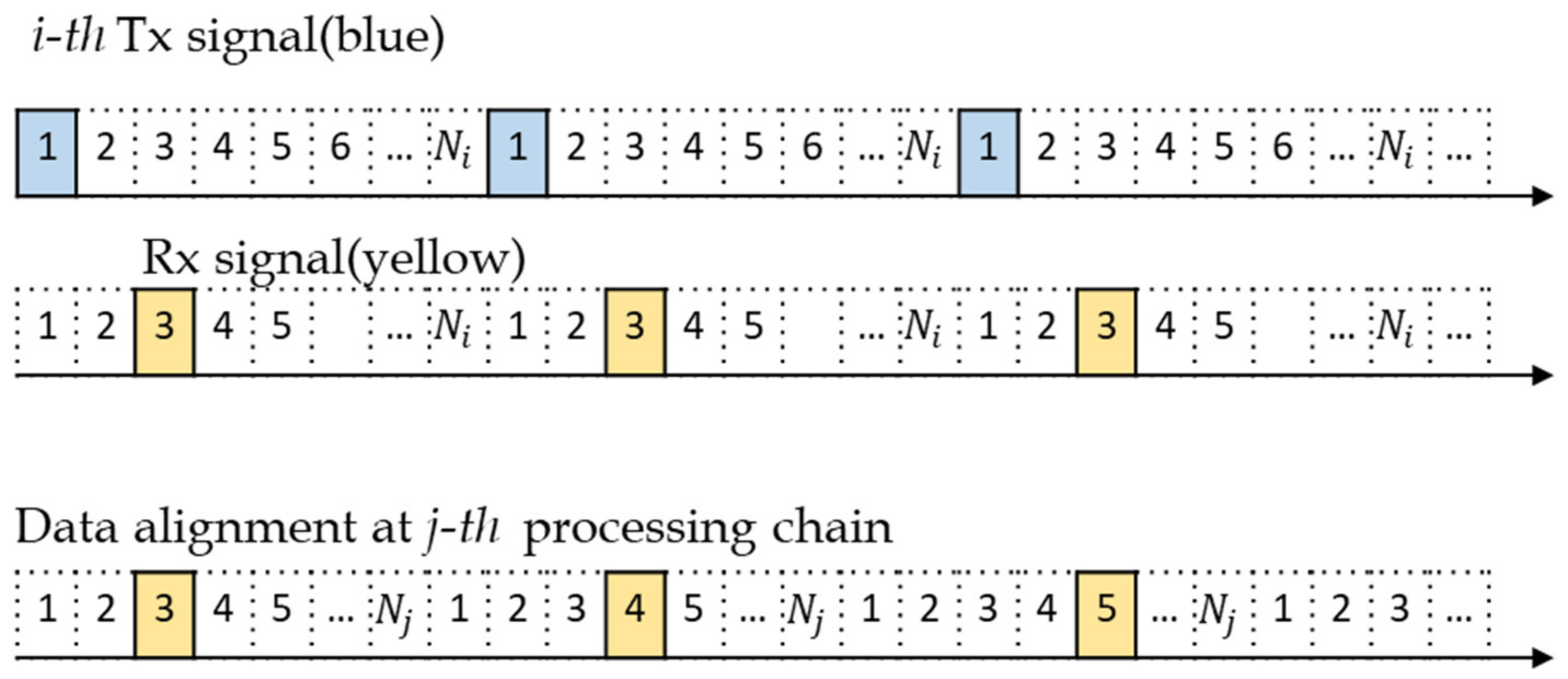
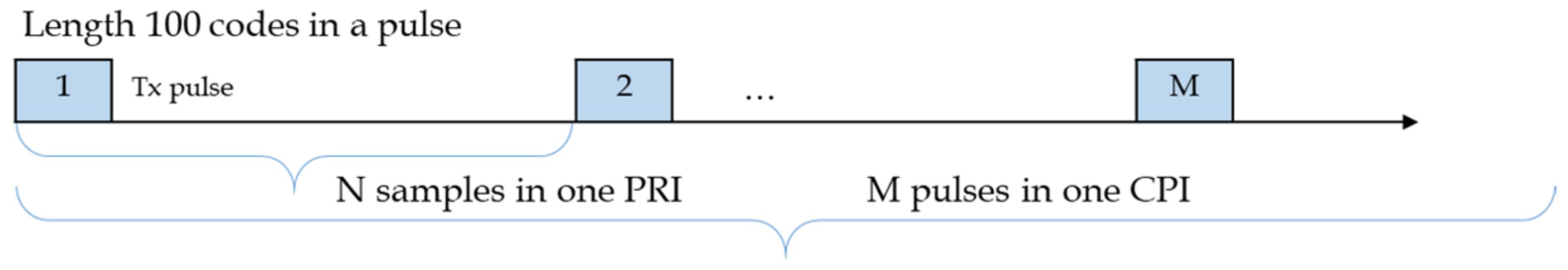
In this section, we present the simulation results obtained by applying the proposed method. The used waveform of the pulse train is described in
Figure 4, and the related parameters satisfying Equation (1) are listed in
Table 1.
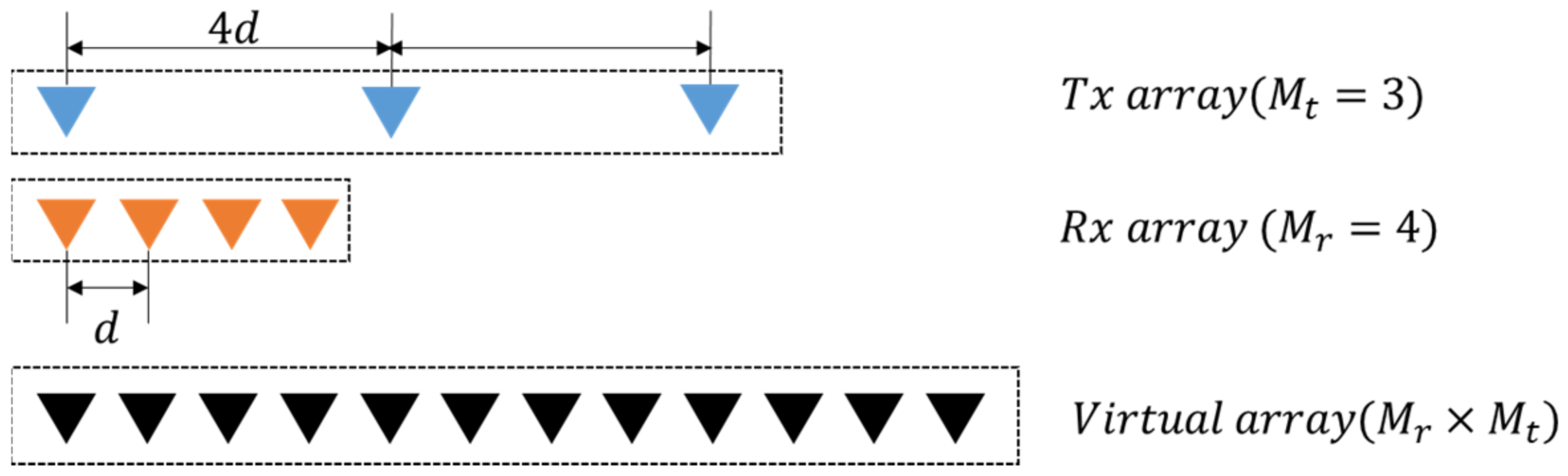
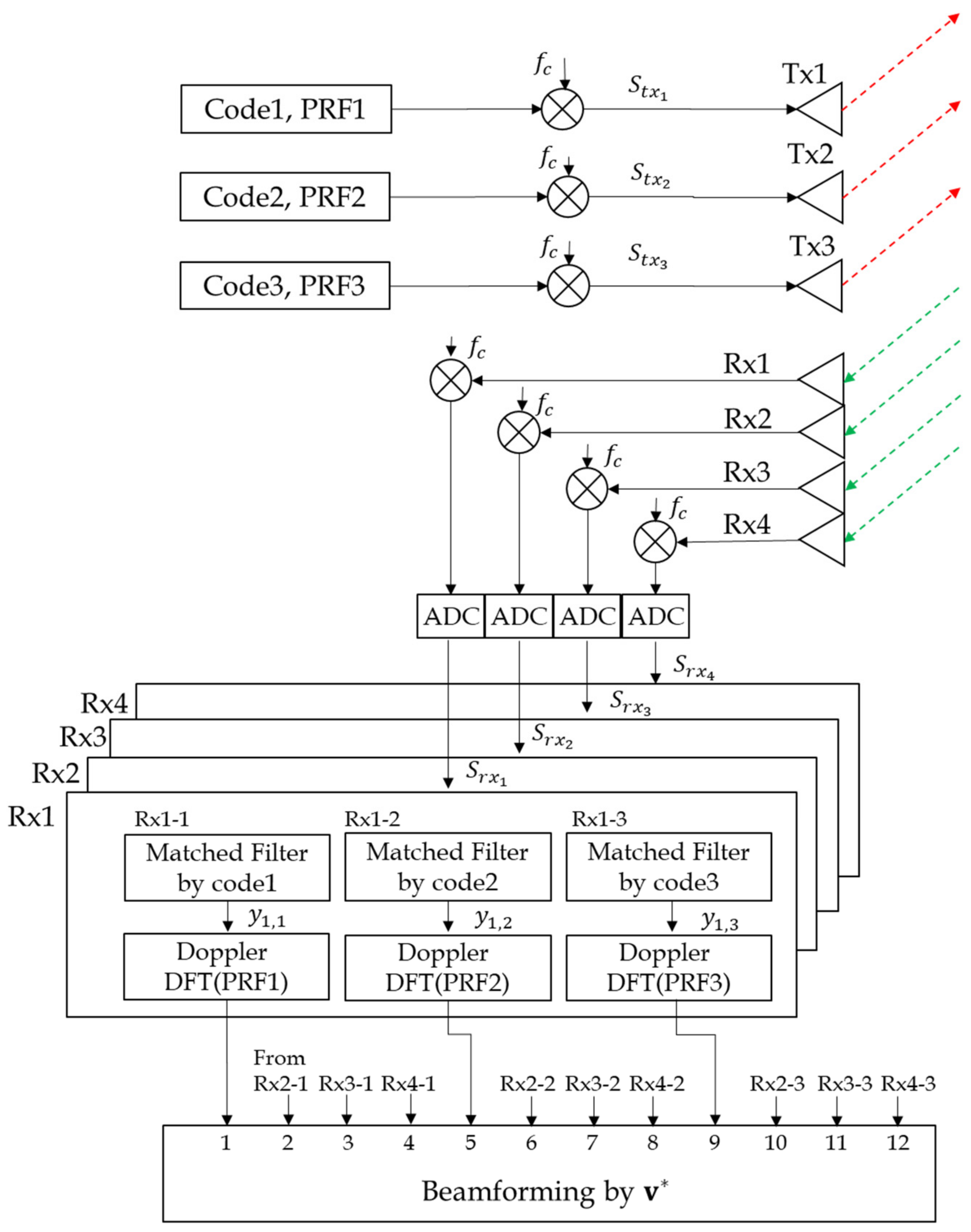
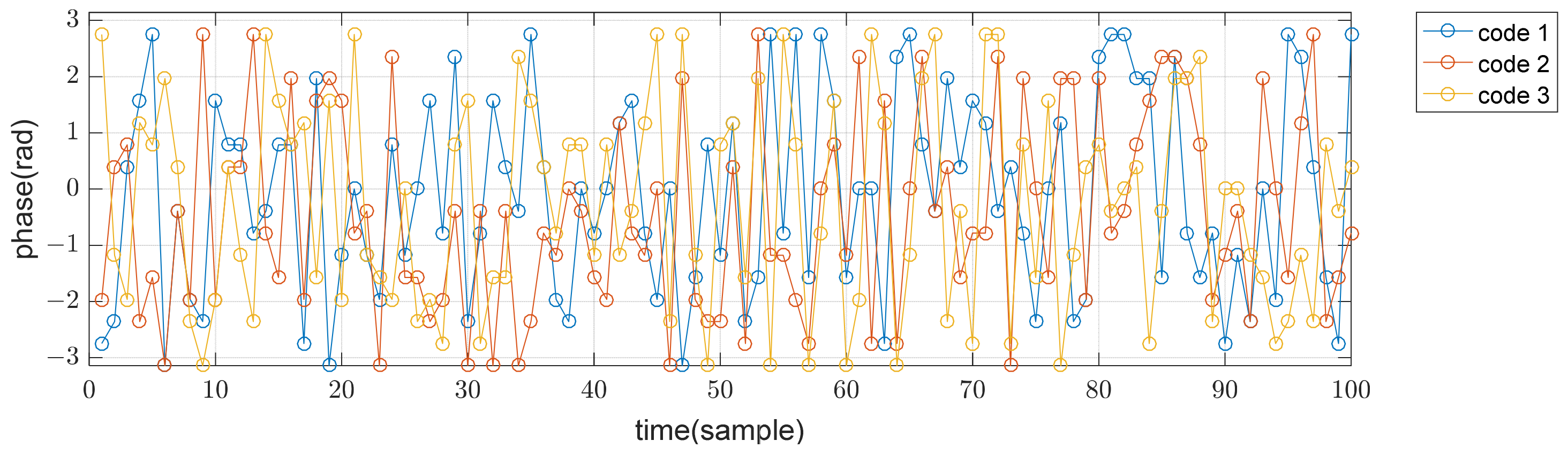
Three transmit arrays and four receive arrays are used for MIMO beamforming, as shown in
Figure 1, and the transmit codes in a pulse are poly phase waveforms of length 100 and 16 phase values, which were designed using a simulated annealing algorithm [
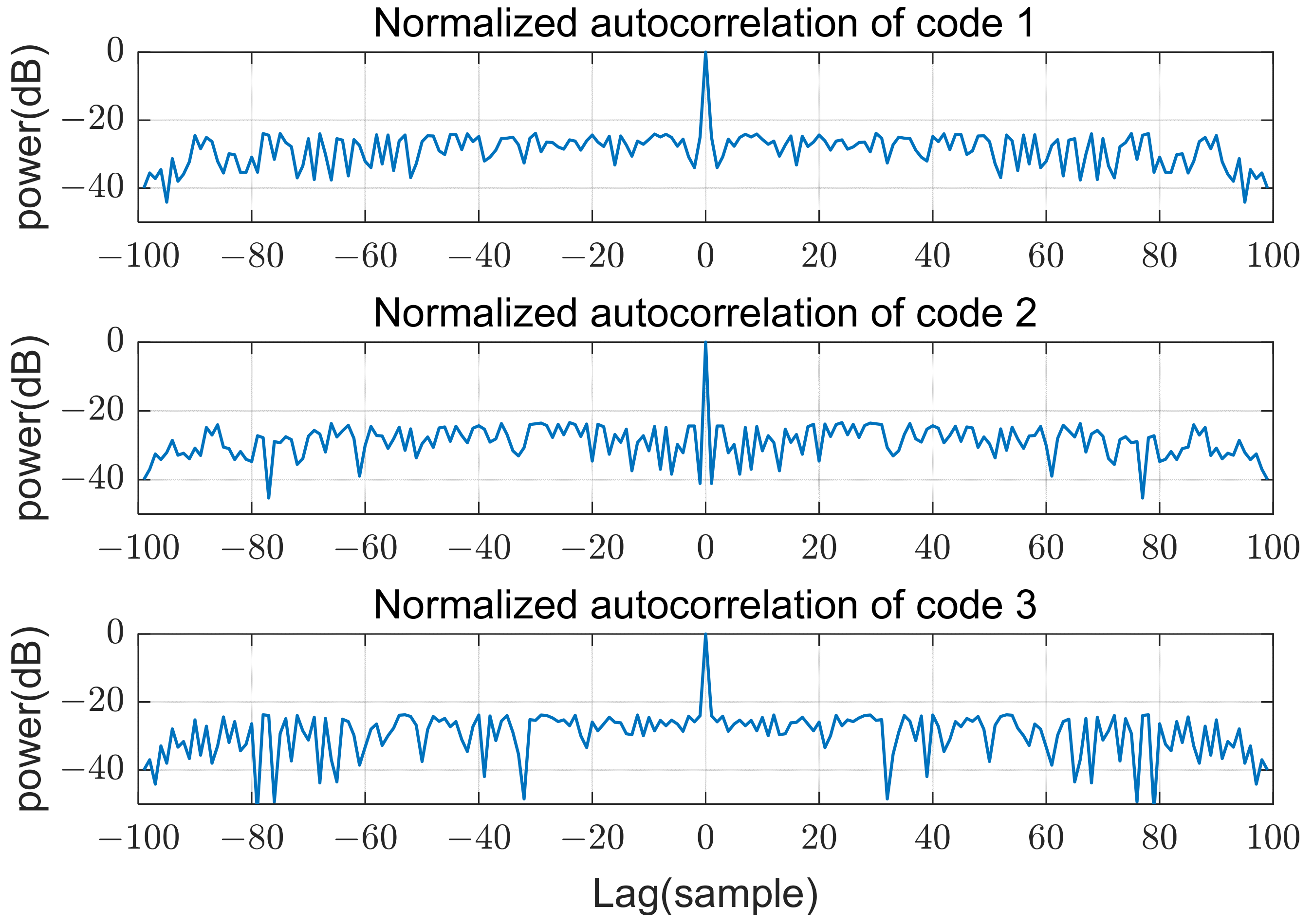
13]. The cost function of this optimization algorithm is the sum of the peak sidelobe level of autocorrelations and the peak level of cross correlations. Phases of the used codes in time domain are shown in
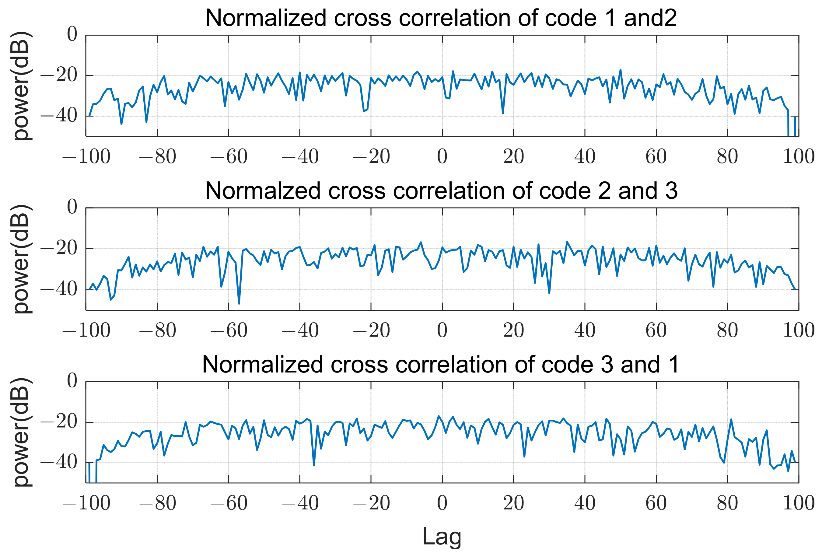
Figure 5. The sidelobe level of autocorrelations and the level of cross-correlations are below −20 dB from the peak, as shown in
Figure 6 and
Figure 7. In the following sections,
refers to the signal-to-noise ratio at each array input.
3.1. Effect of Different PRFs
Figure 8,
Figure 9 and
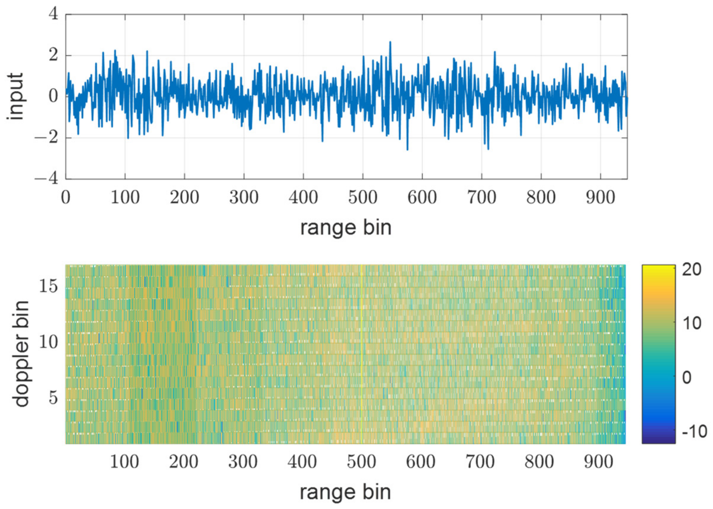
Figure 10 show input data and the power of each filter output when using the same PRF(N) of 945 for all transmit waveforms and using different PRFs listed in
Table 1, respectively.
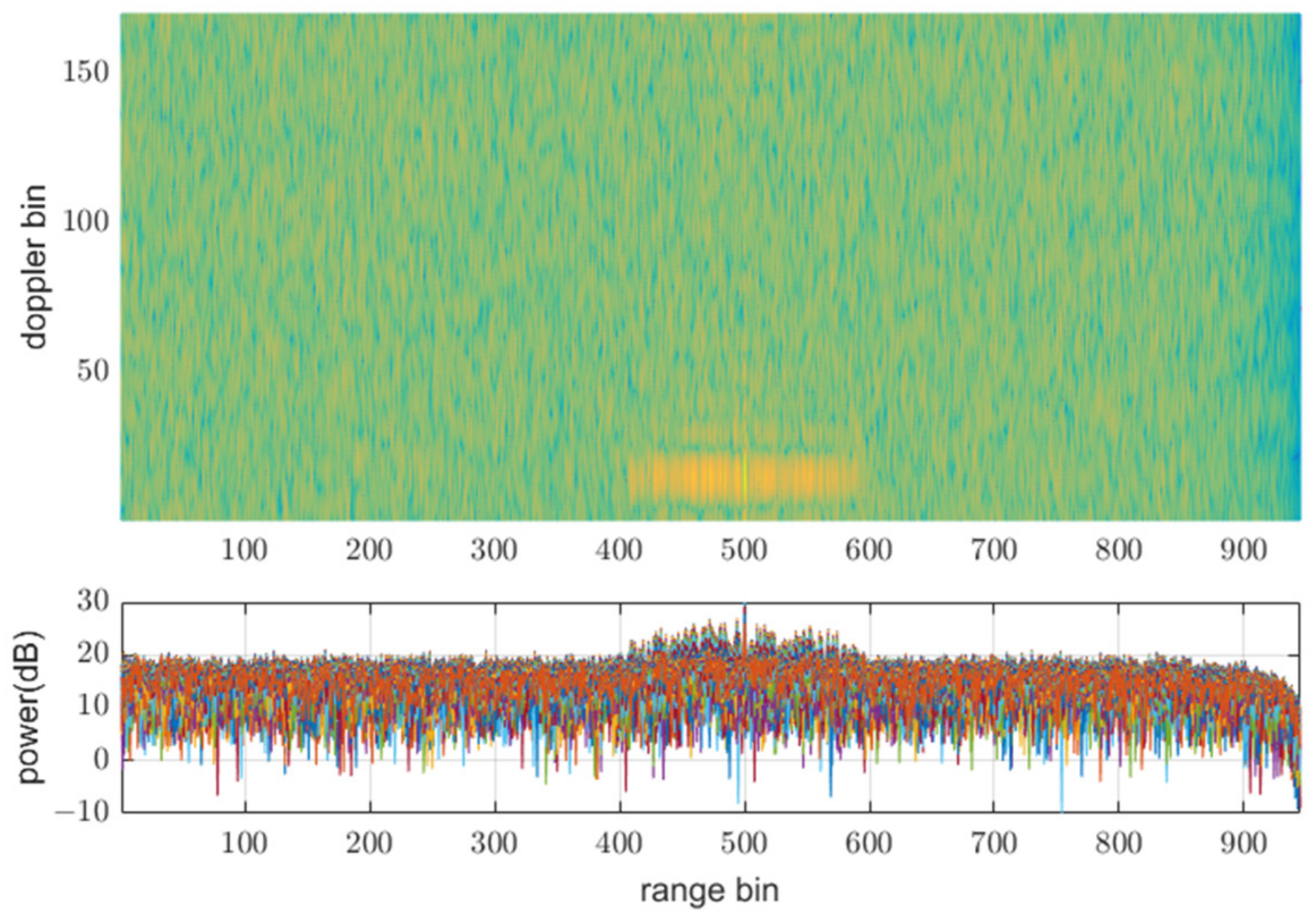
Figure 8 shows that all the reflective signals are in the same range bins, and the power of mismatched codes is represented by near sidelobe levels. In this case, all the matched and mismatched codes are coherently integrated by the doppler processing, so the relative sidelobe level does not change.
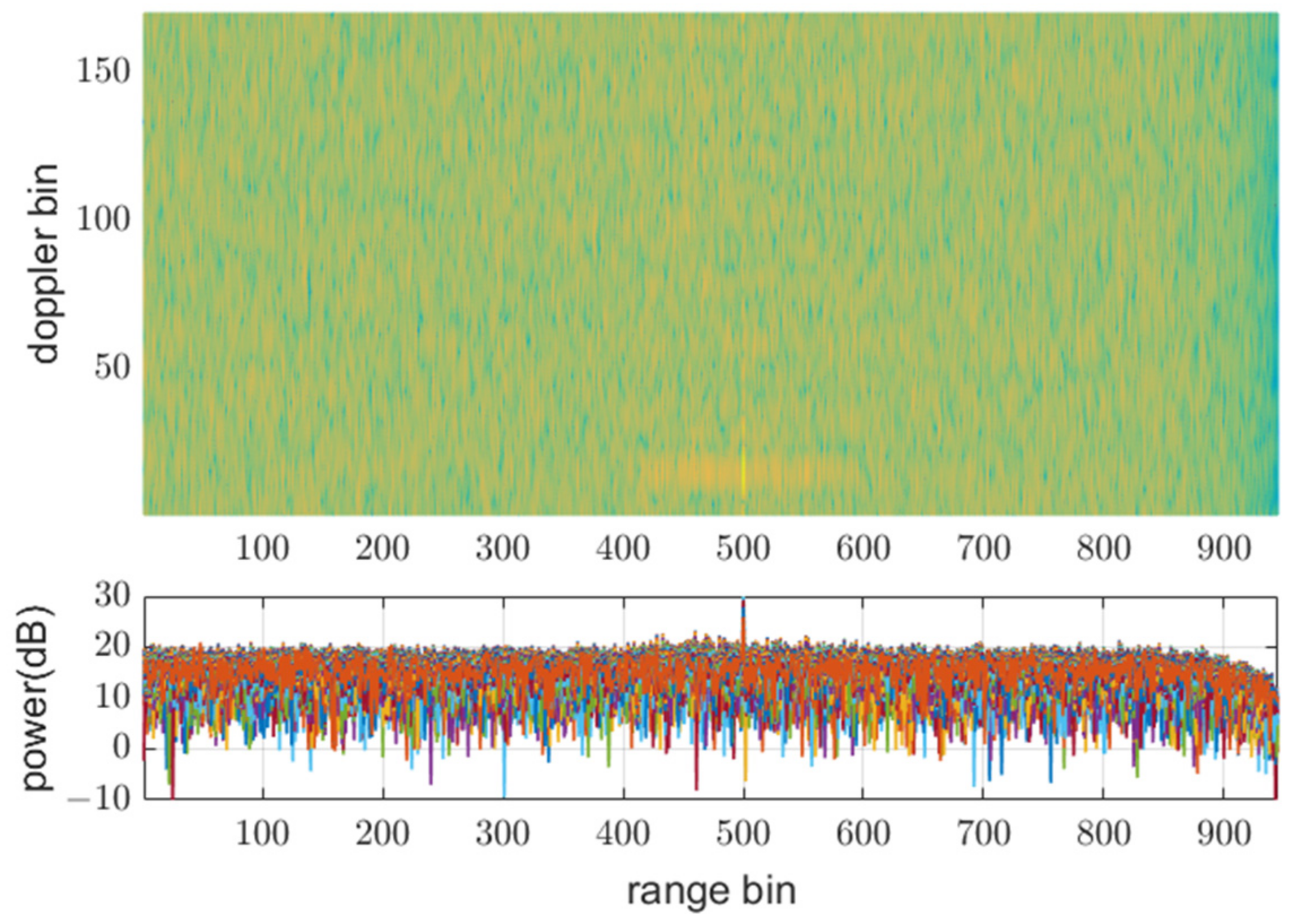
Figure 9 shows the RD map (range doppler map) and power over ranges after doppler processing. The doppler processing was performed ten times
point DFT, that is 170 in this case. On the other hand,
Figure 10 shows that owing to different PRFs, the power of mismatched codes is distributed across different range bins. Thus, they cannot be integrated coherently by doppler processing, and the sidelobe level around the target decreases, as shown in
Figure 11.
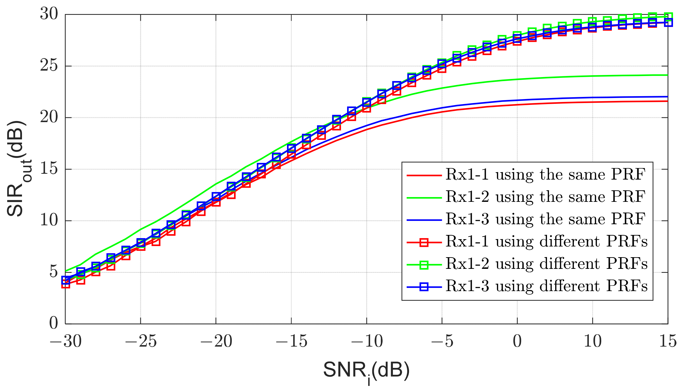
Figure 12 shows SIR after the doppler processing for varying input SNR.
is calculated as the ratio of the power of the target signal to the average power of the surrounding 64 bins. When the SNR is small, the noise constitutes most of the interference power, and
is almost equal to the SNR improved by processing gain, which is about 34dB in this case. However, as the SNR increases, cross-correlations become dominant in interference power and
is no longer improved. The limit of
depends on the cross-correlations and is different at each processing chain.
3.2. MIMO Beamforming and Angle Estimation
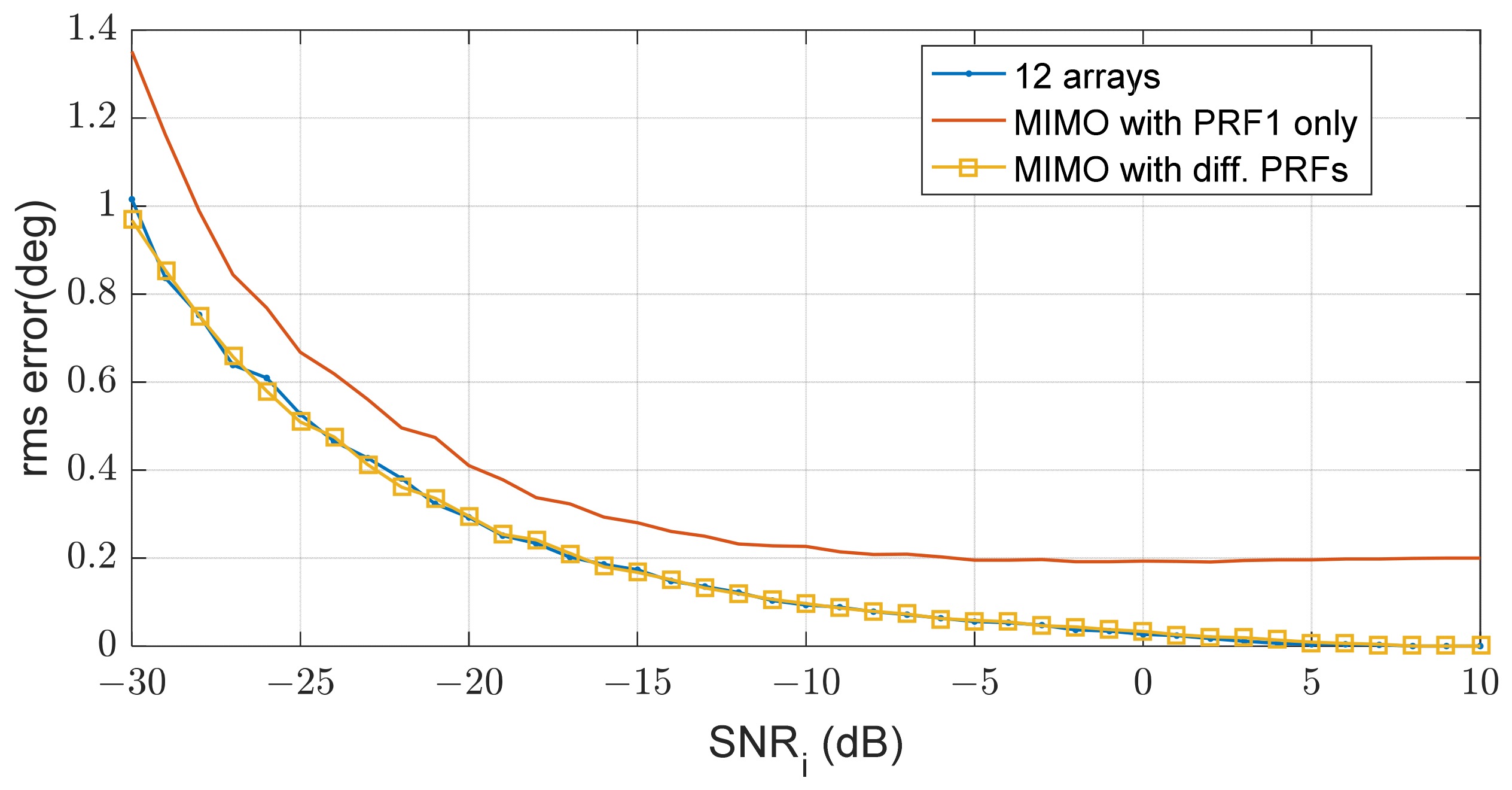
The remaining interference reduces SIR and eventually affects the angular accuracy of MIMO beamforming.
Figure 13 shows the angular estimation error of the target at 15°. The angle estimation is performed by MIMO beamforming according to Equation (3). When all PRFs of the transmit waveforms are the same, there is a limit to the interference level and the angular estimation error is also bounded. However, if the interference level is reduced using different PRFs, the estimation performance is improved. This shows that the RMS error is significantly reduced when using different PRFs compared with using the same PRF and is almost equal to the error of a single 12-array antenna because three transmit signals and four receive arrays synthesizes 12 virtual arrays.
4. Conclusions
We propose a method to use different PRFs in a MIMO beamforming system and demonstrate its performance through simulations. To perform MIMO virtual array beamforming, the transmit signals should be separated in each receiver and must be designed as orthogonal waveforms. In radar systems that cannot synchronize the reflected signal, it is very difficult to eliminate the undesirable mismatched codes for all delay times. Moreover, these signals increase with the signal power and limit the performance when the SNR is high. The proposed method spreads the interference signal to other range bins and achieves additional suppression through doppler processing.
Because this method basically spreads the interference signal over the entire range bins, applications in an environment where there are many targets or a lot of clutter will be difficult. However, it is very effective for improving the angular accuracy of the MIMO radar for a small number of aerial targets.


