
Resilient Adaptive Event-Triggered Load Frequency Control of Network-Based Power Systems against Deception Attacks

Abstract
:1. Introduction
2. Problem Formulation
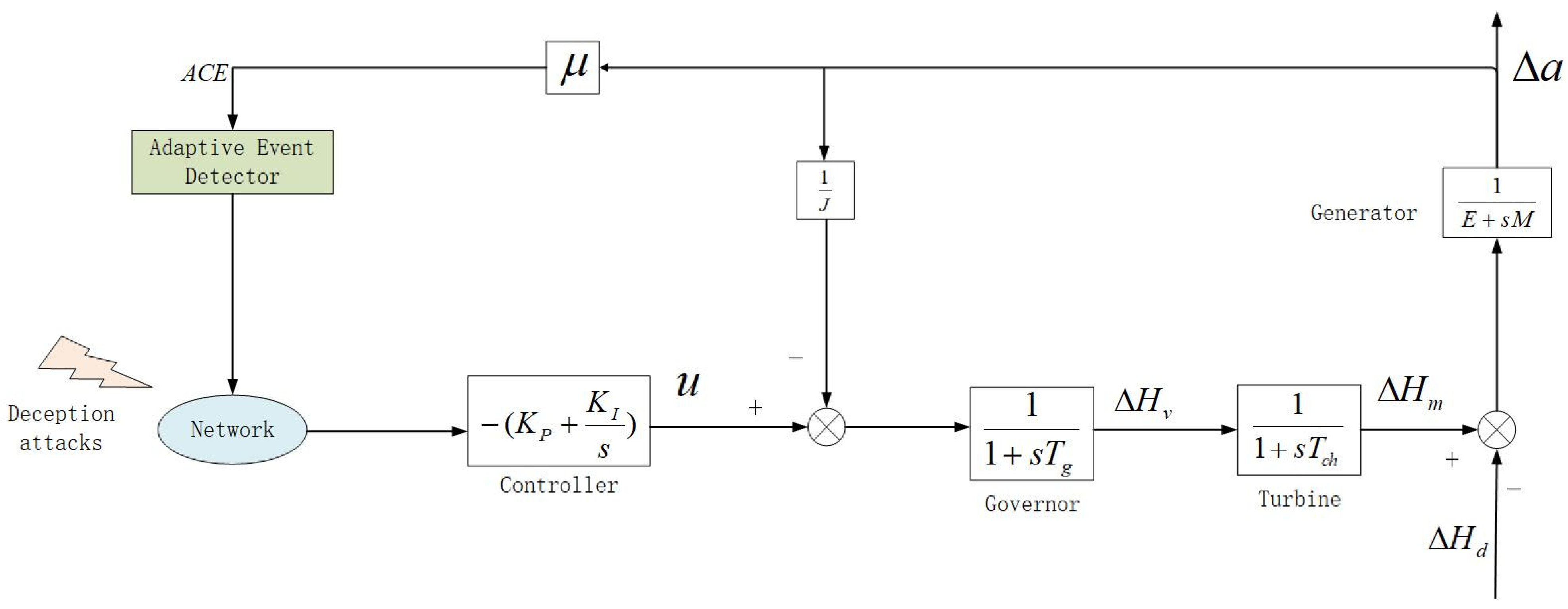
2.1. Description of the LFC Systems
2.2. Adaptive ETS Controller Design
2.3. Closed-Loop Control of LFC Systems
3. Main Results
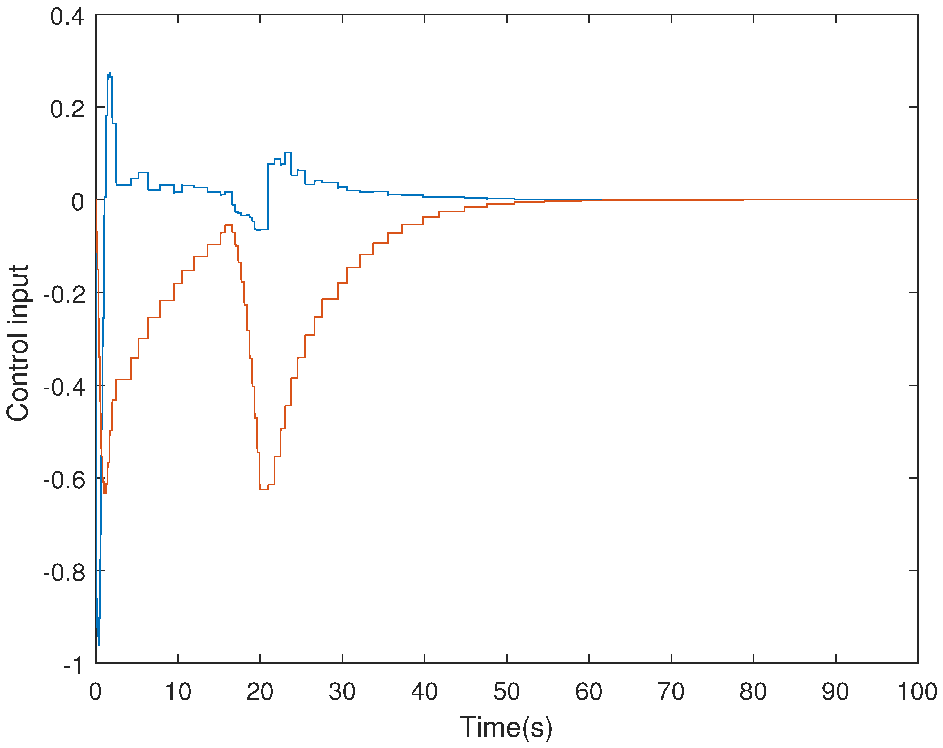
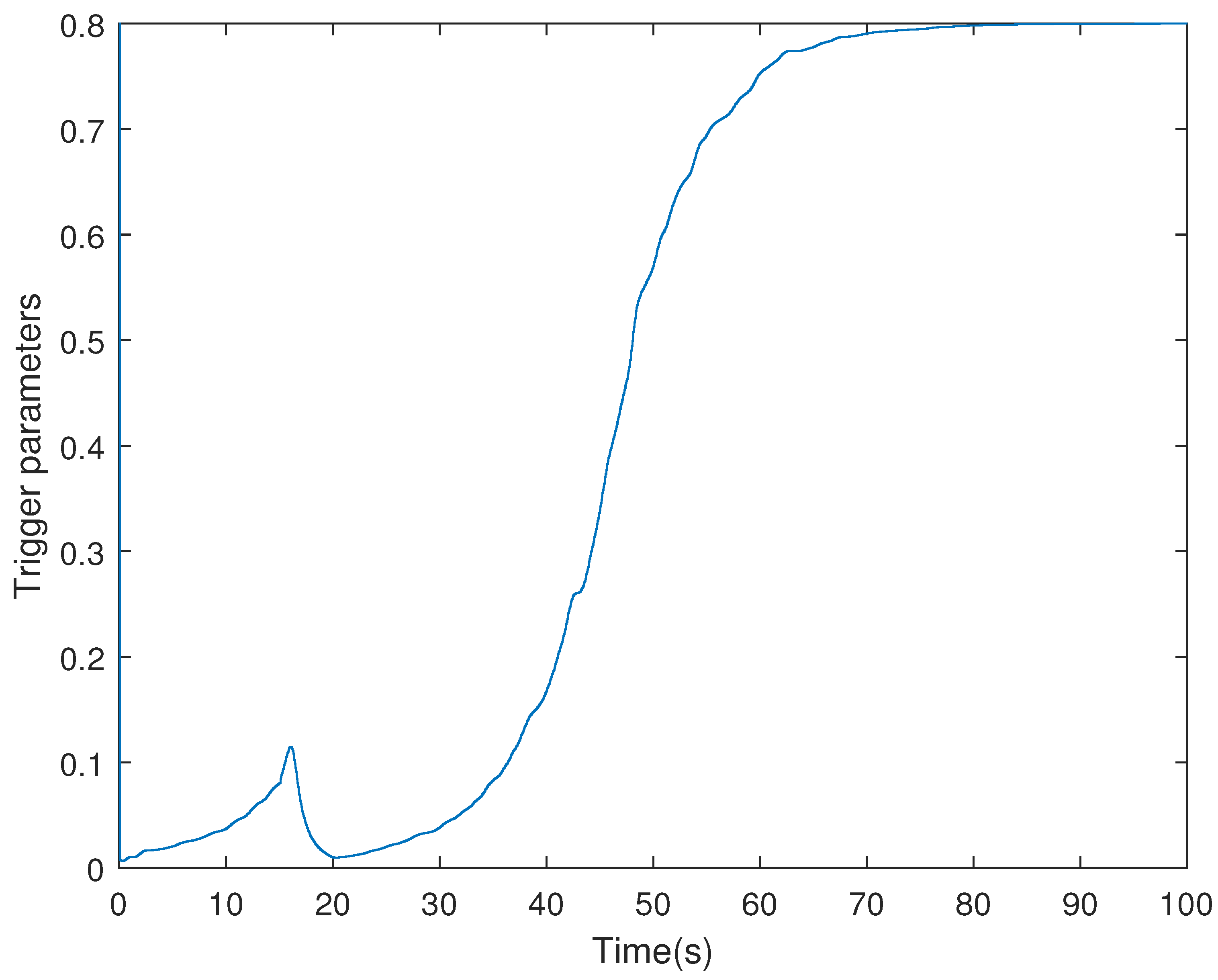
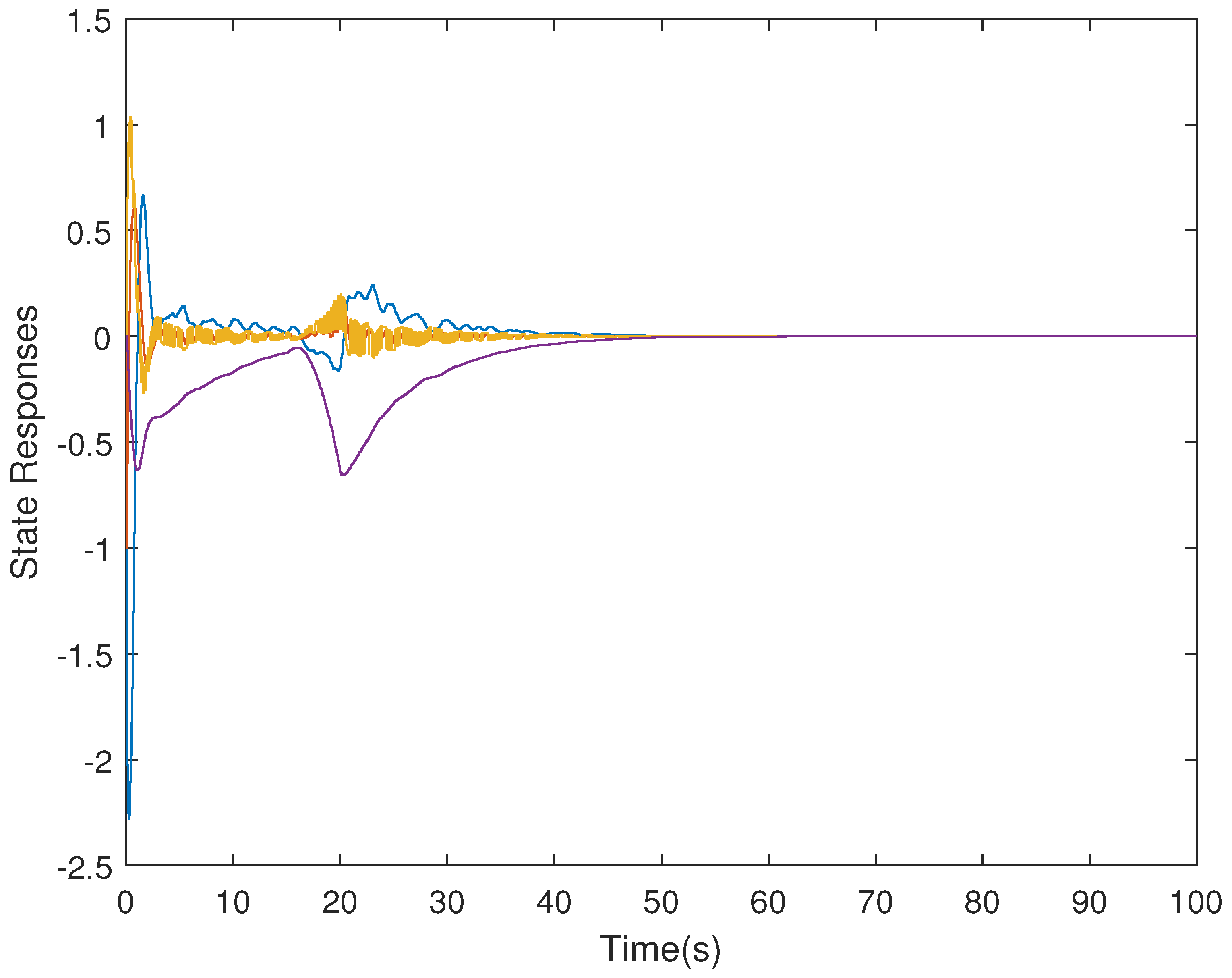
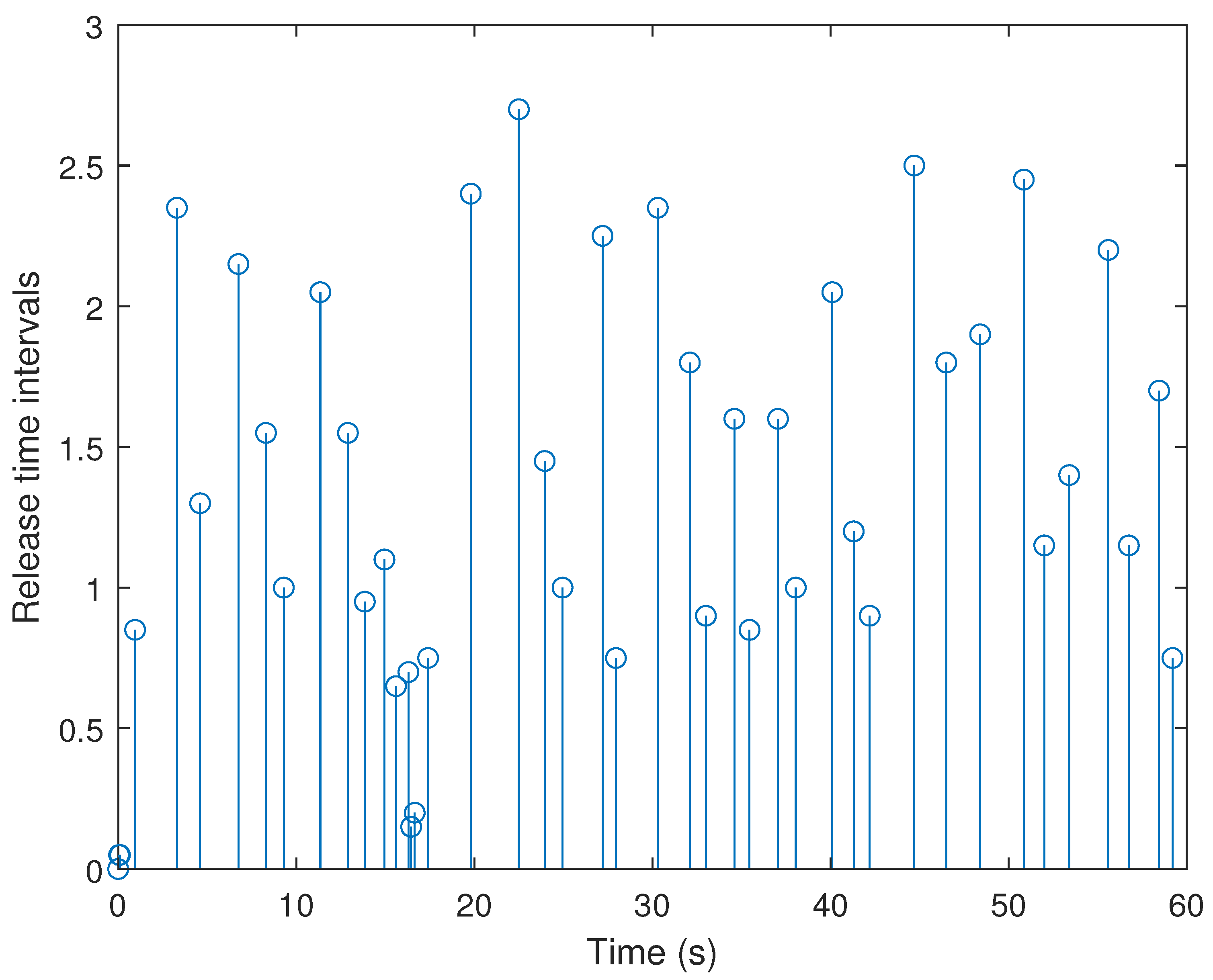
4. Simulation Examples
- (i)
- Consider in adaptive ETS (6) with the parameters .
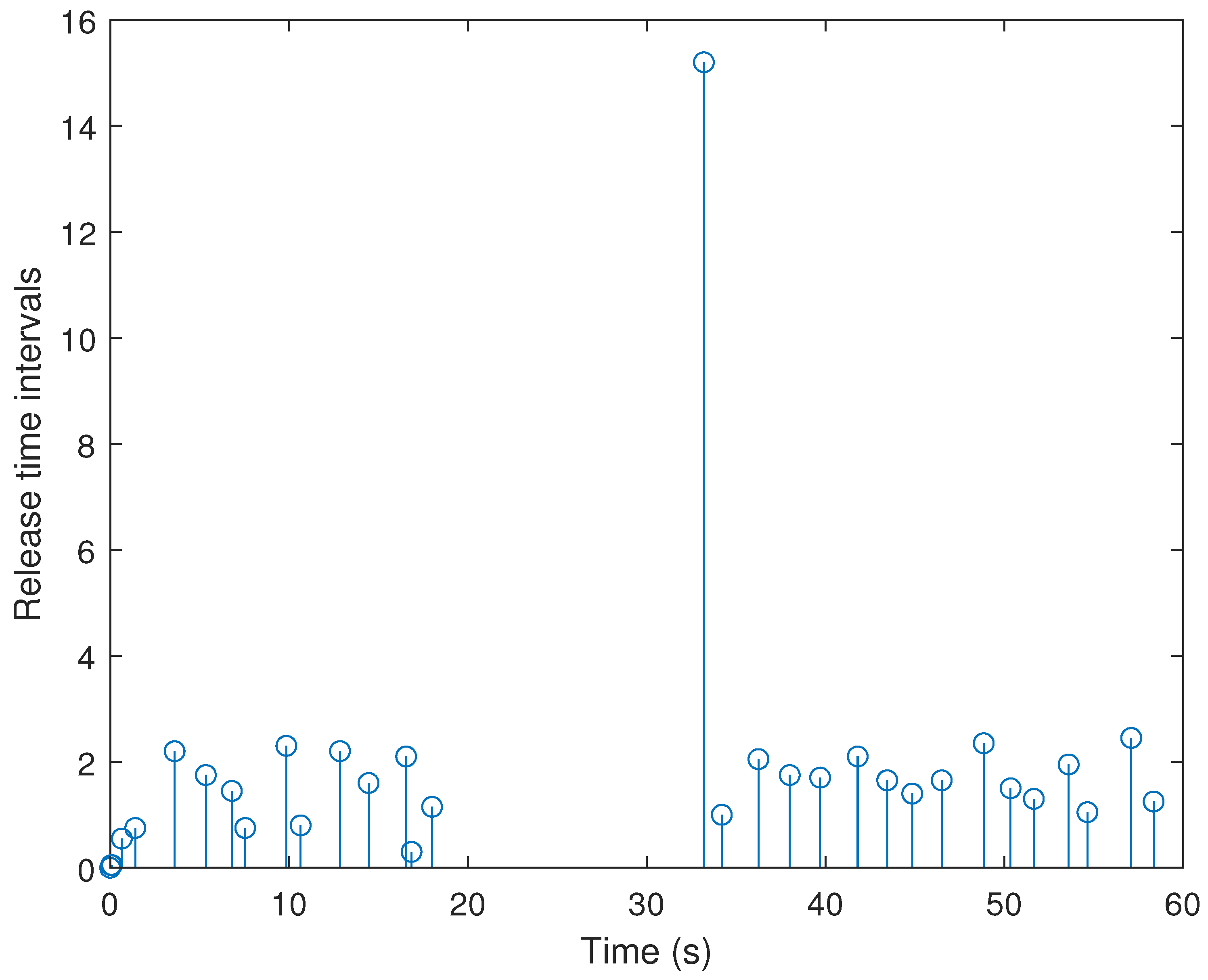
- (ii)
- The ETS in (6) with a fixed threshold is considered, which is reduced to a conventional ETS. Without loss of generality, the threshold is selected to be an average value that can be calculated bywhere , denotes the -th the triggering threshold in adaptive ETS (6) at the -th sampling instant, and NDS is the number of data samplings.
5. Conclusions
Author Contributions
Funding
Institutional Review Board Statement
Informed Consent Statement
Data Availability Statement
Conflicts of Interest
References
- Hossain, M.M.; Chen, P. Observer-based event triggering H∞ LFC for multi-area power systems under DoS attacks. Inf. Sci. 2021, 543, 437–453. [Google Scholar] [CrossRef]
- Liu, J.; Gu, Y.; Zha, L.; Liu, Y.; Cao, J. Event-triggered H∞ load frequency control for multiarea power systems under hybrid cyber attacks. IEEE Trans. Syst. Man Cybern. Syst. 2019, 49, 1665–1678. [Google Scholar] [CrossRef]
- Zhang, C.K.; Jiang, L.; Wu, Q.; He, Y.; Wu, M. Delay-dependent robust load frequency control for time delay power systems. IEEE Trans. Power Syst. 2013, 28, 2192–2201. [Google Scholar] [CrossRef]
- Pappachen, A.; Fathima, A.P. Critical research areas on load frequency control issues in a deregulated power system: A state-of-the-art-of-review. Renew. Sustain. Energy Rev. 2017, 72, 163–177. [Google Scholar] [CrossRef]
- Tang, Y.; He, H.; Wen, J.; Liu, J. Power system stability control for a wind farm based on adaptive dynamic programming. IEEE Trans. Smart Grid. 2017, 6, 166–177. [Google Scholar] [CrossRef]
- Chang, C.; Fu, W. Area load frequency control using fuzzy gain scheduling of PI controllers. Electr. Power Syst. Res. 1997, 42, 145–152. [Google Scholar] [CrossRef]
- Liao, K.; Xu, Y. A robust load frequency control scheme for power systems based on second-order sliding mode and extended disturbance observer. IEEE Trans. Ind. Inf. 2017, 14, 3076–3086. [Google Scholar] [CrossRef]
- Liu, F.; Li, Y.; Cao, Y.; She, J.; Wu, M. A two-layer active disturbance rejection controller design for load frequency control of interconnected power system. IEEE Trans. Power Syst. 2015, 31, 3320–3321. [Google Scholar] [CrossRef]
- Liu, X.; Su, X.; Yang, R. Event-triggered sliding-mode control for multi-area power systems. IEEE Trans. Ind. Electron. 2017, 64, 6732–6741. [Google Scholar]
- Wen, S.; Yu, X.; Zeng, Z.; Wang, J. Event-triggering load frequency control for multiarea power systems with communication delays. IEEE Trans. Ind. Electron. 2016, 63, 1308–1317. [Google Scholar] [CrossRef]
- Liu, S.; Liu, P.X. Distributed model-based control and scheduling for load frequency regulation of smart grids over limited bandwidth networks. IEEE Trans. Ind. Inf. 2017, 14, 1814–1823. [Google Scholar] [CrossRef]
- Basomingera, R.; Choi, Y.J. Learning from routing information for detecting routing misbehavior in ad hoc networks. Sensors 2020, 20, 6275. [Google Scholar] [CrossRef]
- Gu, Z.; Park, J.H.; Yue, D.; Wu, Z.G.; Xie, X.P. Event-triggered security output feedback control for networked interconnected systems subject to cyber-attacks. IEEE Trans. Syst. Man Cybern. Syst. 2020. [Google Scholar] [CrossRef]
- Peng, C.; Yue, D.; Tian, E.; Gu, Z. Observer-based fault detection for networked control systems with network quality of services. Appl. Math. Modell. 2010, 34, 1653–1661. [Google Scholar] [CrossRef]
- Junior, L.; Cristino, W.; Moraes, D.; Coreixas, C. A triggering mechanism for cyber-attacks in naval sensors and systems. Sensors 2021, 21, 3195. [Google Scholar] [CrossRef]
- Fantacci, R.; Nizzi, F.; Pecorella, T.; Pierucci, L.; Roveri, M. False data detection for fog and internet of things networks. Sensors 2019, 19, 4235. [Google Scholar] [CrossRef] [Green Version]
- Yan, S.; Gu, Z.; Park, J.H. Memory-event-triggered H∞ load frequency control of multi-area power systems with cyber-attacks and communication delays. IEEE Trans. Netw. Sci. Eng. 2021, 8, 1571–1583. [Google Scholar] [CrossRef]
- Gu, Z.; Sun, X.; Lam, H.K.; Yue, D.; Xie, X. Event-based secure control of T–S fuzzy based 5-DOF active semi-vehicle suspension systems subject to DoS attacks. IEEE Trans. Fuzzy Syst. 2021. [Google Scholar] [CrossRef]
- Peng, C.; Li, J.; Fei, M. Resilient event-triggering H∞ load frequency control for multi-area power systems with energy-limited DoS attacks. IEEE Trans. Power Syst. 2017, 32, 4110–4118. [Google Scholar] [CrossRef]
- Yue, D.; Tian, E.; Han, Q.L. A delay system method for designing event-triggered controllers of networked control systems. IEEE Trans. Autom. Control. 2013, 58, 475–481. [Google Scholar] [CrossRef]
- Gu, Z.; Yue, D.; Tian, E. On designing of an adaptive event-triggered communication scheme for nonlinear networked interconnected control systems. Inf. Sci. 2018, 422, 257–270. [Google Scholar] [CrossRef]
- Yan, S.; Gu, Z.; Nguang, S.K. Memory-event-triggered H∞ output control of neural networks with mixed delays. IEEE Trans. Neural Netw. Learn. Syst. 2021. [Google Scholar] [CrossRef]
- Zhang, C.; Feng, G.; Qiu, J.; Shen, Y. Control synthesis for a class of linear network-based systems with communication constraints. IEEE Trans. Ind. Electron. 2013, 60, 3339–3348. [Google Scholar] [CrossRef]
- Bemani, A.; Björsell, N. Distributed event triggering algorithm for multi-agent system over a packet dropping network. Sensors 2021, 21, 4835. [Google Scholar] [CrossRef]
- Hu, S.; Yue, D.; Yin, X.; Xie, X.; Ma, Y. Adaptive event-triggered control for nonlinear discrete-time systems. Int. J. Robust Nonlinear Control. 2016, 26, 4104–4125. [Google Scholar] [CrossRef]
- Yan, S.; Shen, M.; Nguang, S.K.; Zhang, G. Event-triggered H∞ control of networked control systems with distributed transmission delay. IEEE Trans. Autom. Control. 2019, 65, 4295–4301. [Google Scholar] [CrossRef]
- Liu, Y.; Chen, Y.; Li, M. Dynamic event-based model predictive load frequency control for power systems under cyber attacks. IEEE Trans. Smart Grid. 2020, 12, 715–725. [Google Scholar] [CrossRef]
- Gu, Z.; Shi, P.; Yue, D.; Yan, S.; Xie, X. Memory-based continuous event-triggered control for networked T–S fuzzy systems against cyber-attacks. IEEE Trans. Fuzzy Syst. 2020, 29, 3118–3129. [Google Scholar] [CrossRef]
- Gu, Z.; Shi, P.; Yue, D.; Ding, Z. Decentralized adaptive event-triggered H∞ filtering for a class of networked nonlinear interconnected system. IEEE Trans. Cybern. 2018, 49, 1570–1579. [Google Scholar] [CrossRef] [Green Version]
- Gu, Z.; Shi, P.; Yue, D. An adaptive event-triggering scheme for networked interconnected control system with stochastic uncertainty. Int. J. Robust Nonlinear Control. 2017, 27, 236–251. [Google Scholar] [CrossRef]
- Peng, C.; Zhang, J.; Yan, H. Adaptive event-triggering H∞ load frequency control for network-based power systems. IEEE Trans. Ind. Electron. 2017, 65, 1685–1694. [Google Scholar] [CrossRef]
- Gu, Z.; Fei, S.M.; Zhao, Y.Q.; Tian, E.G. Robust control of automotive active seat-suspension system subject to actuator saturation. J. Dyn. Syst. Meas. Control. 2014, 136, 041022. [Google Scholar] [CrossRef]
- Pham, T.N.; Nahavandi, S.; Trinh, H. Static output feedback frequency stabilization of time-delay power systems with coordinated electric vehicles state of charge control. IEEE Trans. Power Syst. 2016, 32, 3862–3874. [Google Scholar] [CrossRef]
- Tian, E.; Peng, C. Memory-based event-triggering H∞ load frequency control for power systems under deception attacks. IEEE Trans. Cybern. 2020, 50, 4610–4618. [Google Scholar] [CrossRef]


| Symbol | Meaning |
|---|---|
| Time constant of governor | |
| Mechanical output of the generator | |
| External interference | |
| Control output | |
| Area control error | |
| Generator damping coefficient | |
| Moment of inertia of the generator | |
| Frequency deviation | |
| Frequency bias factor | |
| Speed drop | |
| Time constant of turbine | |
| Position deviation of the valve |
| Physical Quantity | (kgm) | (Hz p.u. MW) | (s) | (s) | ||
|---|---|---|---|---|---|---|
| Values | 0.1667 | 2.4 | 0.08 | 0.3 | 0.425 | 0.0083 |
| Schemes | Controller Gains |
|---|---|
| General ETS with fixed threshold ( = 0.7) | [0.0393 0.5584] |
| This work | [0.0374 0.5270] |
| Schemes | NDS | NPR | DRR |
|---|---|---|---|
| General ETS with fixed threshold ( = 0.7) | 1200 | 43 | 3.58% |
| This work | 1200 | 31 | 2.58% |
Publisher’s Note: MDPI stays neutral with regard to jurisdictional claims in published maps and institutional affiliations. |
© 2021 by the authors. Licensee MDPI, Basel, Switzerland. This article is an open access article distributed under the terms and conditions of the Creative Commons Attribution (CC BY) license (https://creativecommons.org/licenses/by/4.0/).
Share and Cite
Zhang, X.; Yang, F.; Sun, X. Resilient Adaptive Event-Triggered Load Frequency Control of Network-Based Power Systems against Deception Attacks. Sensors 2021, 21, 7047. https://doi.org/10.3390/s21217047
Zhang X, Yang F, Sun X. Resilient Adaptive Event-Triggered Load Frequency Control of Network-Based Power Systems against Deception Attacks. Sensors. 2021; 21(21):7047. https://doi.org/10.3390/s21217047
Chicago/Turabian StyleZhang, Xiao, Fan Yang, and Xiang Sun. 2021. "Resilient Adaptive Event-Triggered Load Frequency Control of Network-Based Power Systems against Deception Attacks" Sensors 21, no. 21: 7047. https://doi.org/10.3390/s21217047
APA StyleZhang, X., Yang, F., & Sun, X. (2021). Resilient Adaptive Event-Triggered Load Frequency Control of Network-Based Power Systems against Deception Attacks. Sensors, 21(21), 7047. https://doi.org/10.3390/s21217047