
Estimation and Control of Cooperative Aerial Manipulators for a Payload with an Arbitrary Center-of-Mass


Abstract
:1. Introduction
1.1. Contribution
1.2. Related Works
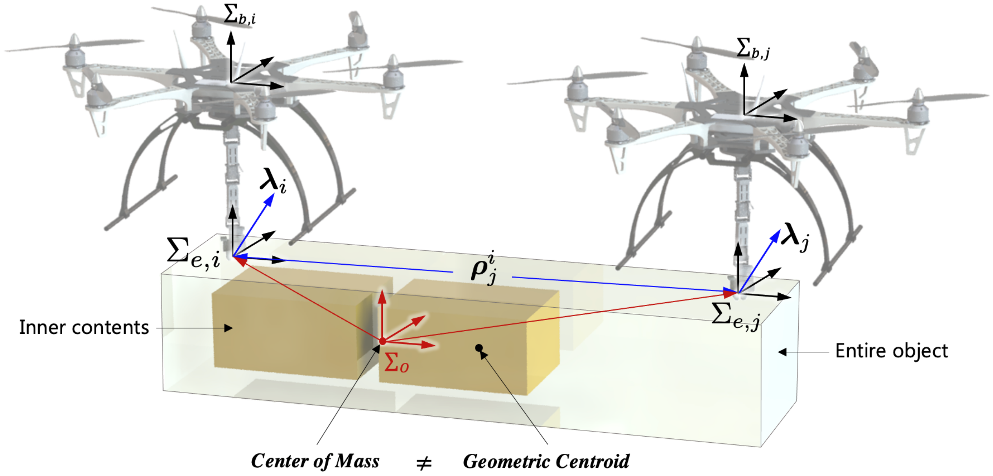
2. Dynamics
2.1. Aerial Manipulator and Payload Dynamics
2.2. Combined Dynamics
3. Kinematic Parameter Estimation and Path Planning
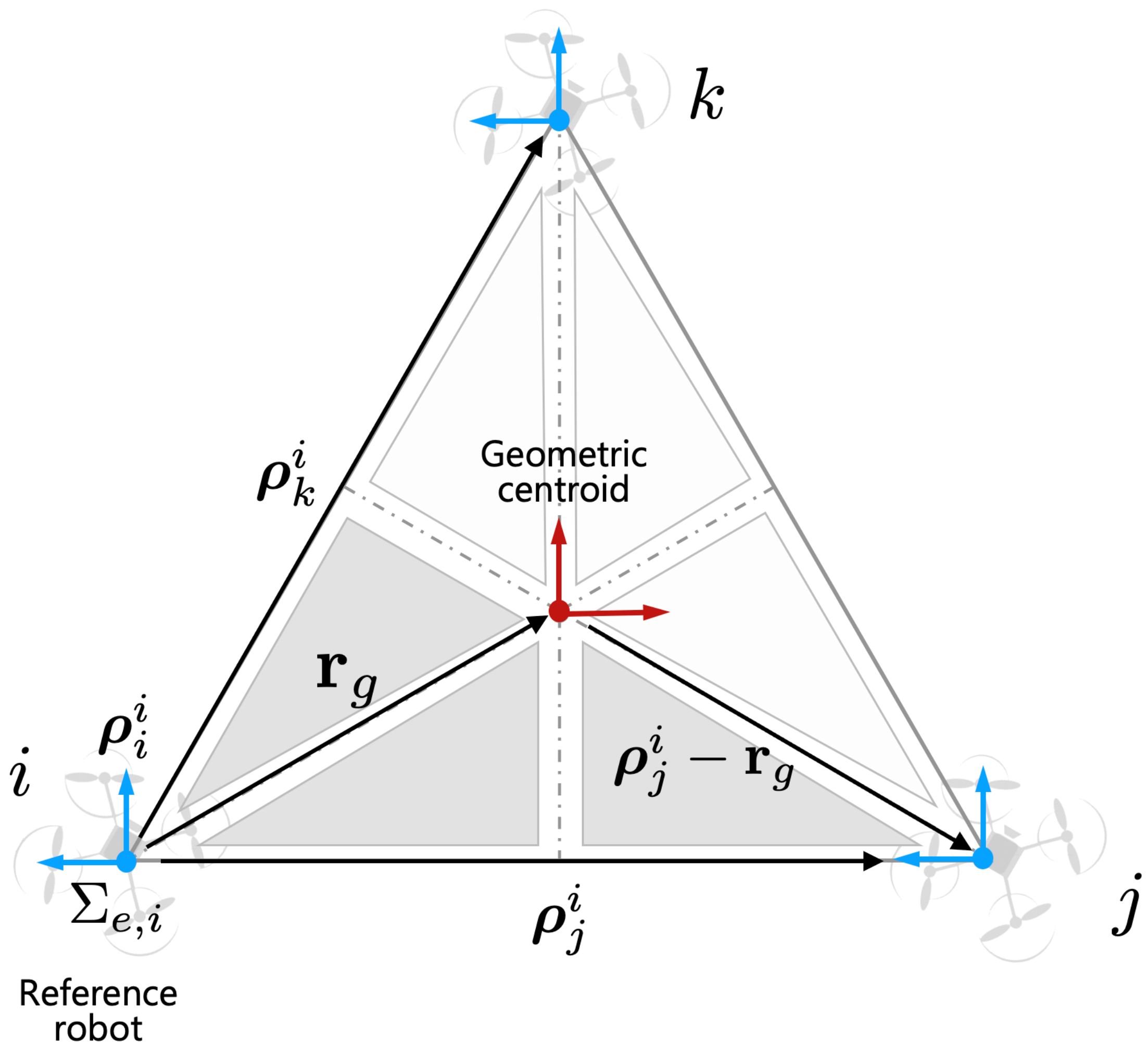
3.1. Kinematic Parameter Estimation
- (1)
- The position/orientation of the end effector grasping on to the payload in the global frame are not known.
- (2)
- At each grasping point, the roll and pitch angle of the end effector is the same for the cooperative aerial manipulators.
- (3)
- Configurations of the payload are previously given, so aerial manipulators know the grasping point of the payload. However, the exact relative distances and heading angles between each robot are unknown.
3.2. Path Planning
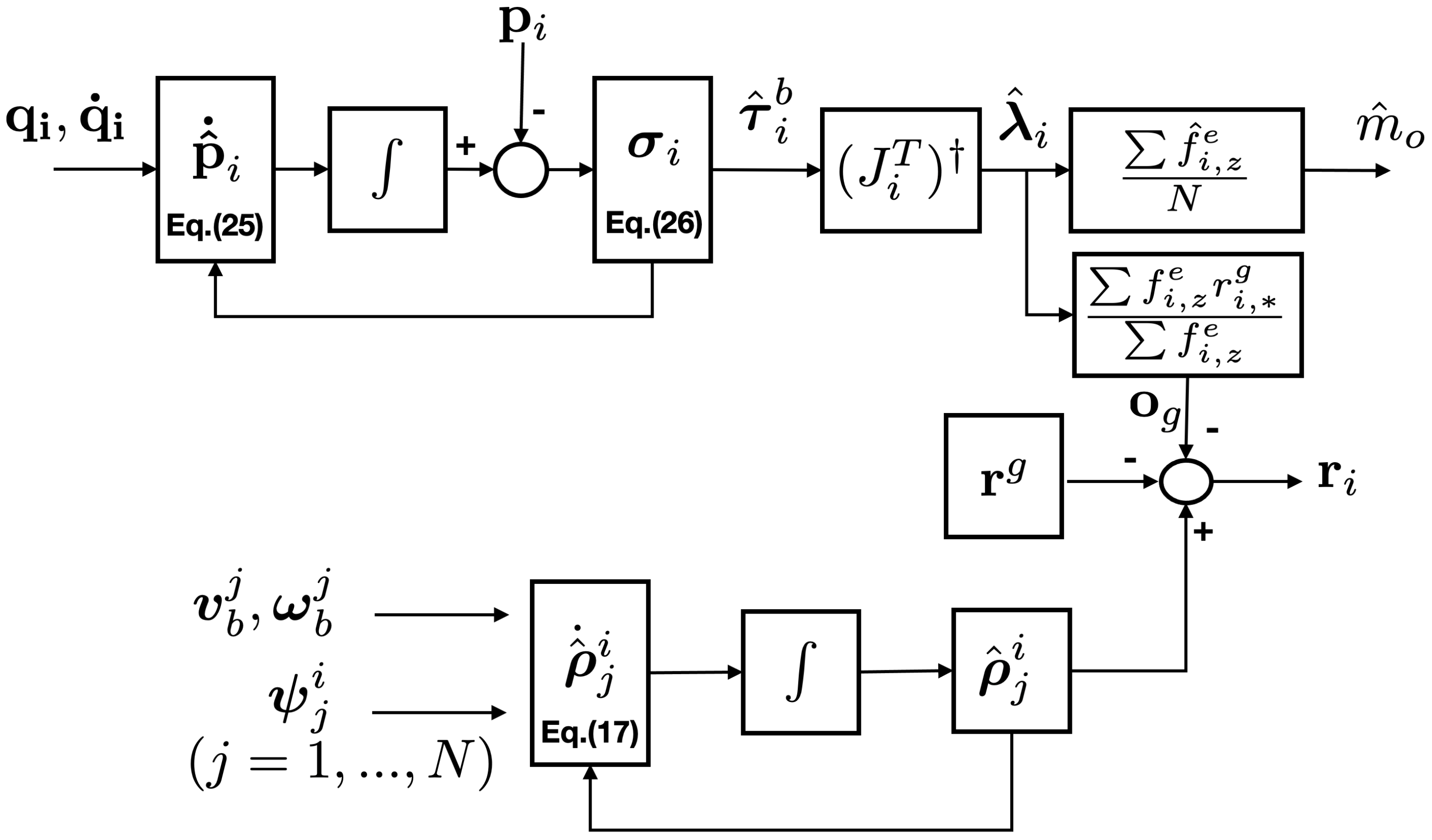
4. Dynamic Parameter Estimation
4.1. First-Order Momentum Observer
4.2. Dynamic Parameter Estimation with Sliding Mode Momentum Observer
5. Simulations
5.1. Simulation Environment
- (1)
- The main uncertainty is caused by the measurement noise, .
- (2)
- The noise in the measured state and has a high frequency and is zero mean.
- 0.2 m in x and y direction and 0.1 m in the z direction
- 0.01 rad in attitude and 0.1 rad in joint angles.
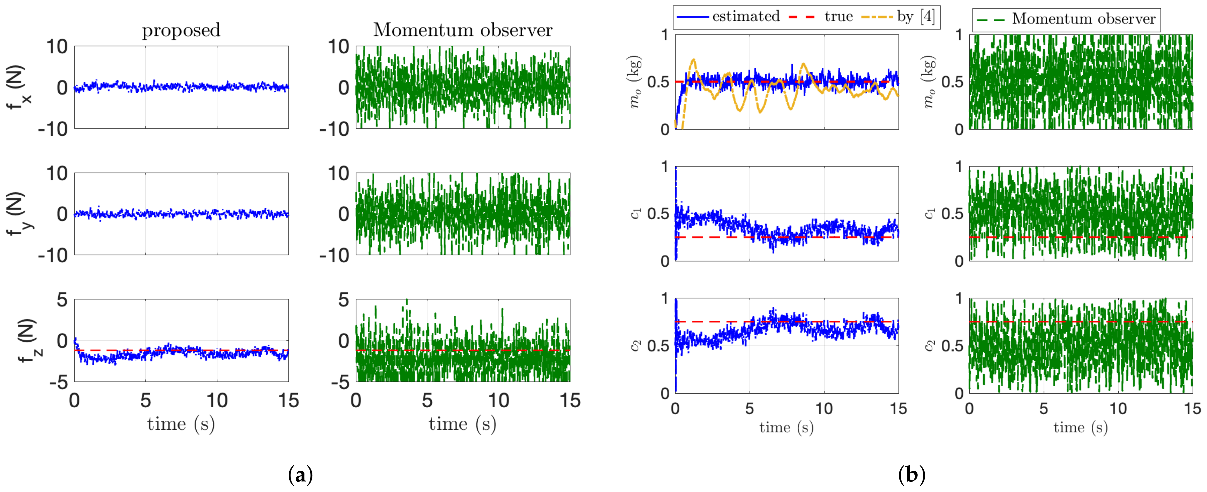
5.2. Simulation Results
6. Conclusions
Author Contributions
Funding
Institutional Review Board Statement
Informed Consent Statement
Data Availability Statement
Conflicts of Interest
References
- Huang, H.; Savkin, A.V.; Huang, C. Scheduling of a parcel delivery system consisting of an aerial drone interacting with public transportation vehicles. Sensors 2020, 20, 2045. [Google Scholar] [CrossRef] [PubMed] [Green Version]
- Mellinger, D.; Lindsey, Q.; Shomin, M.; Kumar, V. Design, modeling, estimation and control for aerial grasping and manipulation. In Proceedings of the 2011 IEEE/RSJ International Conference on Intelligent Robots and Systems, San Francisco, CA, USA, 25–30 September 2011; pp. 2668–2673. [Google Scholar]
- Eoh, G.; Park, T.H. Cooperative Object Transportation Using Curriculum-Based Deep Reinforcement Learning. Sensors 2021, 21, 4780. [Google Scholar] [CrossRef] [PubMed]
- Lee, H.; Kim, H.; Kim, W.; Kim, H.J. An Integrated Framework for Cooperative Aerial Manipulators in Unknown Environments. IEEE Robot. Autom. Lett. 2018, 3, 2307–2314. [Google Scholar] [CrossRef]
- Lee, H.; Son, C.Y.; Kim, H.J. Collision-Free Path Planning for Cooperative Aerial Manipulators Under Velocity and Curvature Constraints. IEEE Access 2019, 7, 171153–171162. [Google Scholar] [CrossRef]
- Kim, S.; Seo, H.; Shin, J.; Kim, H.J. Cooperative Aerial Manipulation Using Multirotors With Multi-DOF Robotic Arms. IEEE/ASME Trans. Mechatron. 2018, 23, 702–713. [Google Scholar] [CrossRef]
- Tagliabue, A.; Kamel, M.; Siegwart, R.; Nieto, J. Robust collaborative object transportation using multiple mavs. Int. J. Robot. Res. 2019, 38, 1020–1044. [Google Scholar] [CrossRef] [Green Version]
- Thapa, S.; Bai, H.; Acosta, J.Á. Cooperative Aerial Manipulation with Decentralized Adaptive Force-Consensus Control. J. Intell. Robot. Syst. 2020, 97, 171–183. [Google Scholar] [CrossRef]
- Marino, A.; Pierri, F. A two stage approach for distributed cooperative manipulation of an unknown object without explicit communication and unknown number of robots. Robot. Auton. Syst. 2018, 103, 122–133. [Google Scholar] [CrossRef]
- Aghili, F. Adaptive Control of Manipulators Forming Closed Kinematic Chain With Inaccurate Kinematic Model. IEEE/ASME Trans. Mechatron. 2013, 18, 1544–1554. [Google Scholar] [CrossRef]
- Pierri, F.; Nigro, M.; Muscio, G.; Caccavale, F. Cooperative Manipulation of an Unknown Object via Omnidirectional Unmanned Aerial Vehicles. J. Intell. Robot. Syst. 2020, 100, 1635–1649. [Google Scholar] [CrossRef]
- Suarez, A.; Heredia, G.; Ollero, A. Physical-Virtual Impedance Control in Ultralightweight and Compliant Dual-Arm Aerial Manipulators. IEEE Robot. Autom. Lett. 2018, 3, 2553–2560. [Google Scholar] [CrossRef] [Green Version]
- Franchi, A.; Petitti, A.; Rizzo, A. Decentralized parameter estimation and observation for cooperative mobile manipulation of an unknown load using noisy measurements. In Proceedings of the 2015 IEEE International Conference on Robotics and Automation (ICRA), Seattle, WA, USA, 26–30 May 2015; pp. 5517–5522. [Google Scholar]
- Ruggiero, F.; Cacace, J.; Sadeghian, H.; Lippiello, V. Passivity-based control of VToL UAVs with a momentum-based estimator of external wrench and unmodeled dynamics. Robot. Auton. Syst. 2015, 72, 139–151. [Google Scholar] [CrossRef]
- Tomić, T.; Ott, C.; Haddadin, S. External Wrench Estimation, Collision Detection, and Reflex Reaction for Flying Robots. IEEE Trans. Robot. 2017, 33, 1467–1482. [Google Scholar] [CrossRef]
- Ryll, M.; Muscio, G.; Pierri, F.; Cataldi, E.; Antonelli, G.; Caccavale, F.; Bicego, D.; Franchi, A. 6D interaction control with aerial robots: The flying end-effector paradigm. Int. J. Robot. Res. 2019, 38, 1045–1062. [Google Scholar] [CrossRef] [Green Version]
- Yang, H.; Lee, D. Hierarchical cooperative control framework of multiple quadrotor-manipulator systems. In Proceedings of the 2015 IEEE International Conference on Robotics and Automation (ICRA), Seattle, WA, USA, 26–30 May 2015; pp. 4656–4662. [Google Scholar] [CrossRef]
- Korayem, A.H.; Nekoo, S.R.; Korayem, M.H. Optimal sliding mode control design based on the state-dependent Riccati equation for cooperative manipulators to increase dynamic load carrying capacity. Robotica 2019, 37, 321–337. [Google Scholar] [CrossRef]
- Ćehajić, D.; gen Dohmann, P.B.; Hirche, S. Estimating unknown object dynamics in human-robot manipulation tasks. In Proceedings of the 2017 IEEE International Conference on Robotics and Automation (ICRA), Singapore, 29 May–3 June 2017; pp. 1730–1737. [Google Scholar]
- Morín, D.G.; Araujo, J.; Tayamon, S.; Andersson, L.A.A. Autonomous Cooperative Flight of Rigidly Attached Quadcopters. In Proceedings of the 2019 International Conference on Robotics and Automation (ICRA), Montreal, QC, Canada, 20–24 May 2019; pp. 5309–5315. [Google Scholar]
- Erhart, S.; Hirche, S. Model and Analysis of the Interaction Dynamics in Cooperative Manipulation Tasks. IEEE Trans. Robot. 2016, 32, 672–683. [Google Scholar] [CrossRef]
- Lee, H.; Kim, H.; Kim, H.J. Planning and Control for Collision-Free Cooperative Aerial Transportation. IEEE Trans. Autom. Sci. Eng. 2018, 15, 189–201. [Google Scholar] [CrossRef]
- Montijano, E.; Cristofalo, E.; Zhou, D.; Schwager, M.; Sagüés, C. Vision-Based Distributed Formation Control Without an External Positioning System. IEEE Trans. Robot. 2016, 32, 339–351. [Google Scholar] [CrossRef]
- Cantieri, A.; Ferraz, M.; Szekir, G.; Antônio Teixeira, M.; Lima, J.; Schneider Oliveira, A.; Aurélio Wehrmeister, M. Cooperative UAV–UGV Autonomous Power Pylon Inspection: An Investigation of Cooperative Outdoor Vehicle Positioning Architecture. Sensors 2020, 20, 6384. [Google Scholar] [CrossRef] [PubMed]
- De Luca, A.; Mattone, R. Sensorless Robot Collision Detection and Hybrid Force/Motion Control. In Proceedings of the 2005 IEEE International Conference on Robotics and Automation, Barcelona, Spain, 18–22 April 2005; pp. 999–1004. [Google Scholar]
- Han, L.; Xu, W.; Li, B.; Kang, P. Collision Detection and Coordinated Compliance Control for a Dual-Arm Robot Without Force/Torque Sensing Based on Momentum Observer. IEEE/ASME Trans. Mechatron. 2019, 24, 2261–2272. [Google Scholar] [CrossRef]
- Garofalo, G.; Mansfeld, N.; Jankowski, J.; Ott, C. Sliding Mode Momentum Observers for Estimation of External Torques and Joint Acceleration. In Proceedings of the 2019 International Conference on Robotics and Automation (ICRA), Montreal, QC, Canada, 20–24 May 2019; pp. 6117–6123. [Google Scholar]
- Hibbeler, R.C. Engineering Mechanics: Statics; Pearson Educación: Ciudad de México, Mexico, 2004; Volume 1. [Google Scholar]
- Moreno, J.A.; Osorio, M. A Lyapunov approach to second-order sliding mode controllers and observers. In Proceedings of the 2008 47th IEEE Conference on Decision and Control, Cancun, Mexico, 9–11 December 2008; pp. 2856–2861. [Google Scholar] [CrossRef]
- Wahrburg, A.; Robertsson, A.; Matthias, B.; Dai, F.; Ding, H. Improving contact force estimation accuracy by optimal redundancy resolution. In Proceedings of the 2016 IEEE/RSJ International Conference on Intelligent Robots and Systems (IROS), Daejeon, Korea, 9–14 October 2016; pp. 3735–3741. [Google Scholar]


| Term | Definition |
|---|---|
| a state vector for i-th aerial manipulator | |
| a control input | |
| an applied force at the i-th end-effector | |
| an external wrench applied to | |
| a force balance term | |
| a linear velocity at | |
| an angular velocity at | |
| a mass of a payload | |
| a relative heading angle between and | |
| a vector from to | |
| a grasp matrix | |
| the geometric centroid of the payload wr.t. the leader robot | |
| a relative distance from to | |
| a generalized momentum | |
| an estimated external wrench | |
| a vector from the geometric centroid to |
| Proposed Algorithm | Comparison Algorithm | ||||
|---|---|---|---|---|---|
| Parameter | (std) | (std) | Ref | ||
| [kg] | 0.1968 (0.0094) | 0.1883 | 0.4859 (0.0134) | 1.0196 | by [14] |
| 0.3275 (0.0104) | 0.4604 | by [4] | |||
| [m] | 0.1265 (0.0107) | 0.0242 | 0.2015 (0.0479) | 0.1120 | |
| [m] | 0.2456 (0.0463) | 0.0363 | 0.2550 (0.0680) | 0.1004 | by [10] |
| [m] | 0.0549 (0.0055) | 0.0048 | 0.4081 (0.1073) | 0.3757 | |
Publisher’s Note: MDPI stays neutral with regard to jurisdictional claims in published maps and institutional affiliations. |
© 2021 by the authors. Licensee MDPI, Basel, Switzerland. This article is an open access article distributed under the terms and conditions of the Creative Commons Attribution (CC BY) license (https://creativecommons.org/licenses/by/4.0/).
Share and Cite
Lee, H.; Kim, U. Estimation and Control of Cooperative Aerial Manipulators for a Payload with an Arbitrary Center-of-Mass. Sensors 2021, 21, 6452. https://doi.org/10.3390/s21196452
Lee H, Kim U. Estimation and Control of Cooperative Aerial Manipulators for a Payload with an Arbitrary Center-of-Mass. Sensors. 2021; 21(19):6452. https://doi.org/10.3390/s21196452
Chicago/Turabian StyleLee, Hyeonbeom, and Uikyum Kim. 2021. "Estimation and Control of Cooperative Aerial Manipulators for a Payload with an Arbitrary Center-of-Mass" Sensors 21, no. 19: 6452. https://doi.org/10.3390/s21196452
APA StyleLee, H., & Kim, U. (2021). Estimation and Control of Cooperative Aerial Manipulators for a Payload with an Arbitrary Center-of-Mass. Sensors, 21(19), 6452. https://doi.org/10.3390/s21196452