
Wide Two-Degree-of-Freedom Static Laser Scanner with Miniaturized Transmission Mechanism and Piezoelectric Actuation


Abstract
:1. Introduction
2. Methods: Design
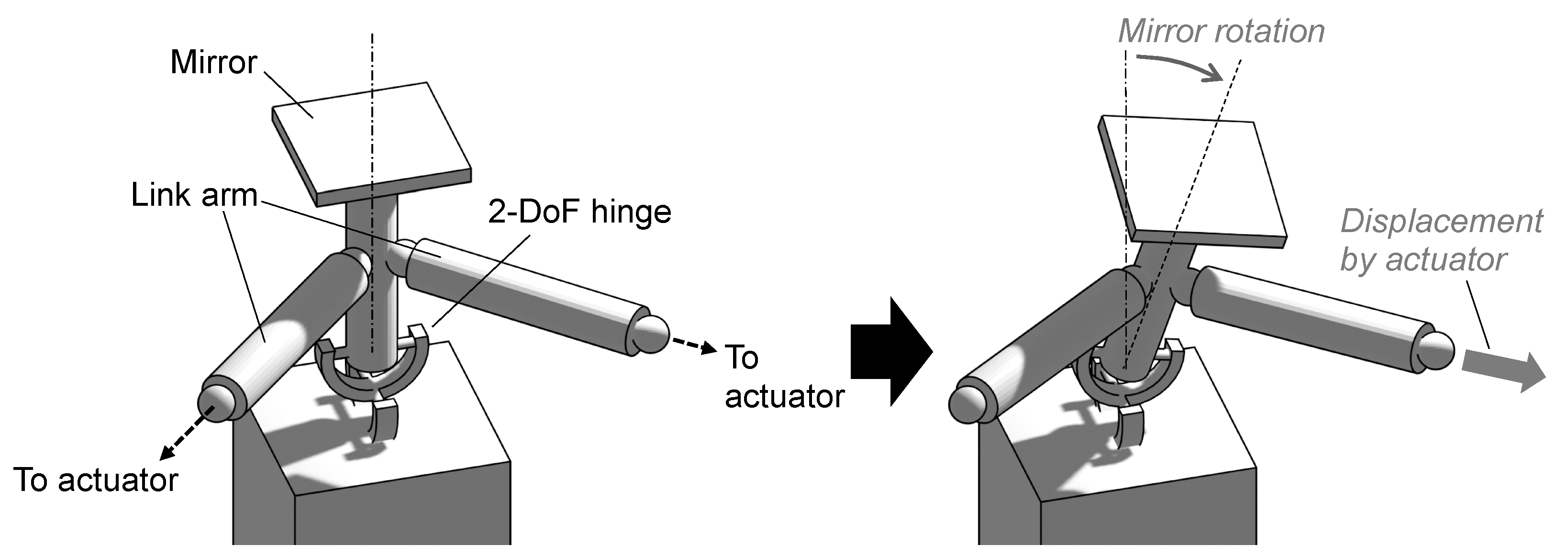
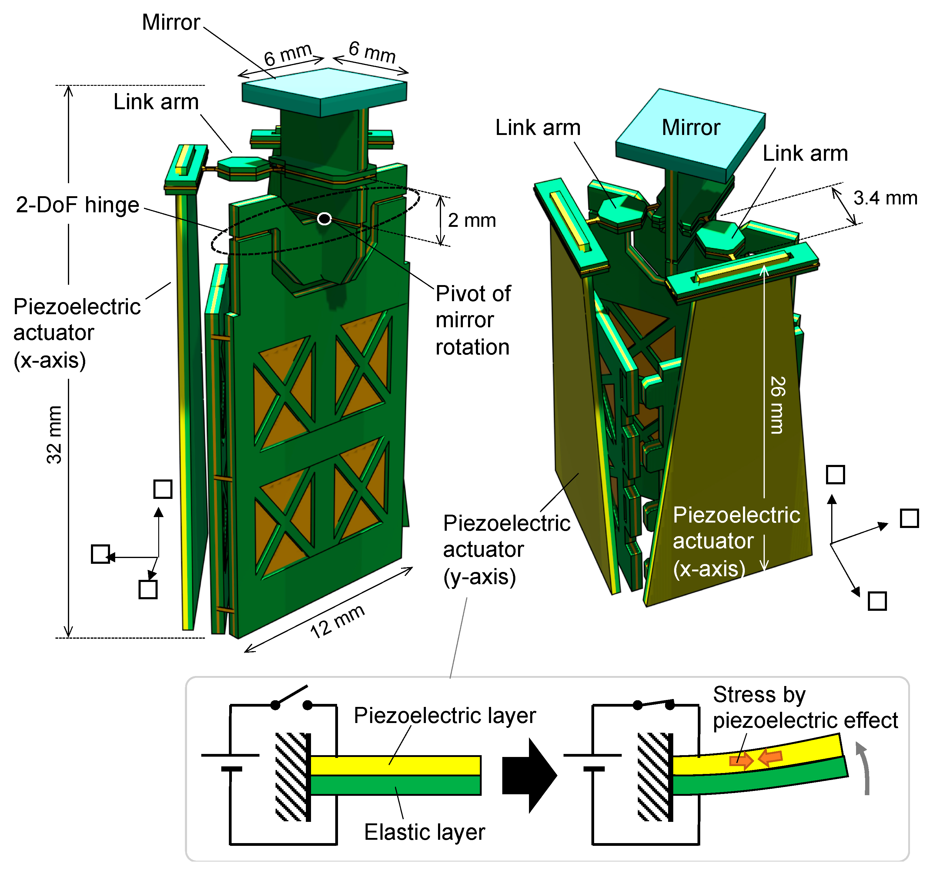
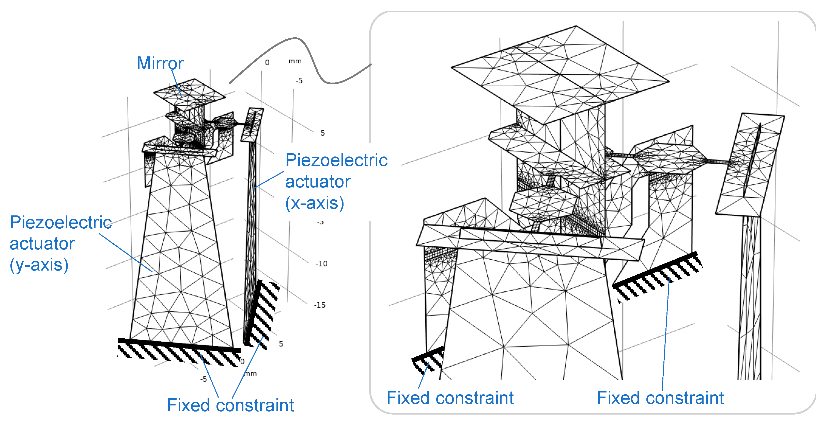
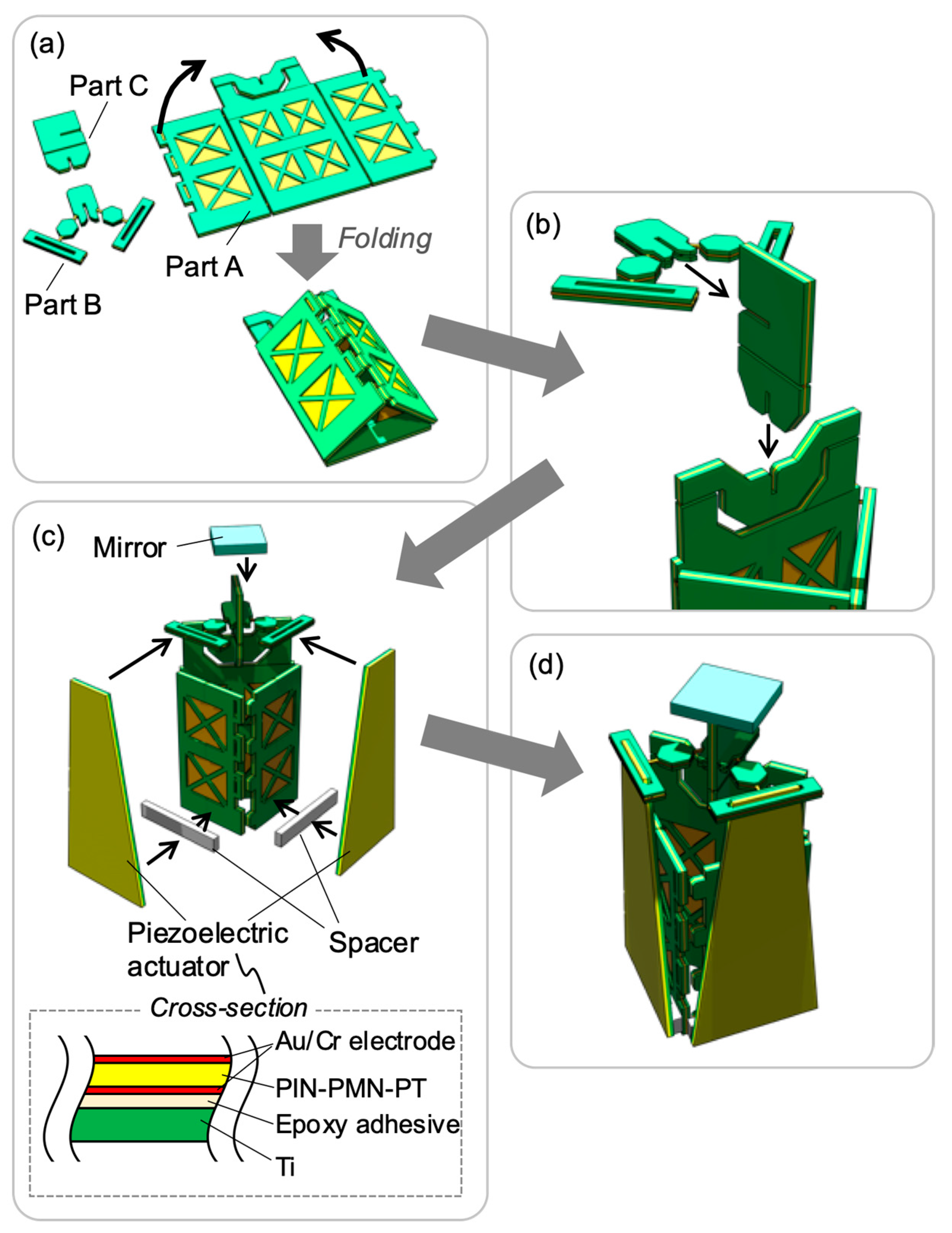
2.1. Structure of Developed Laser Scanner
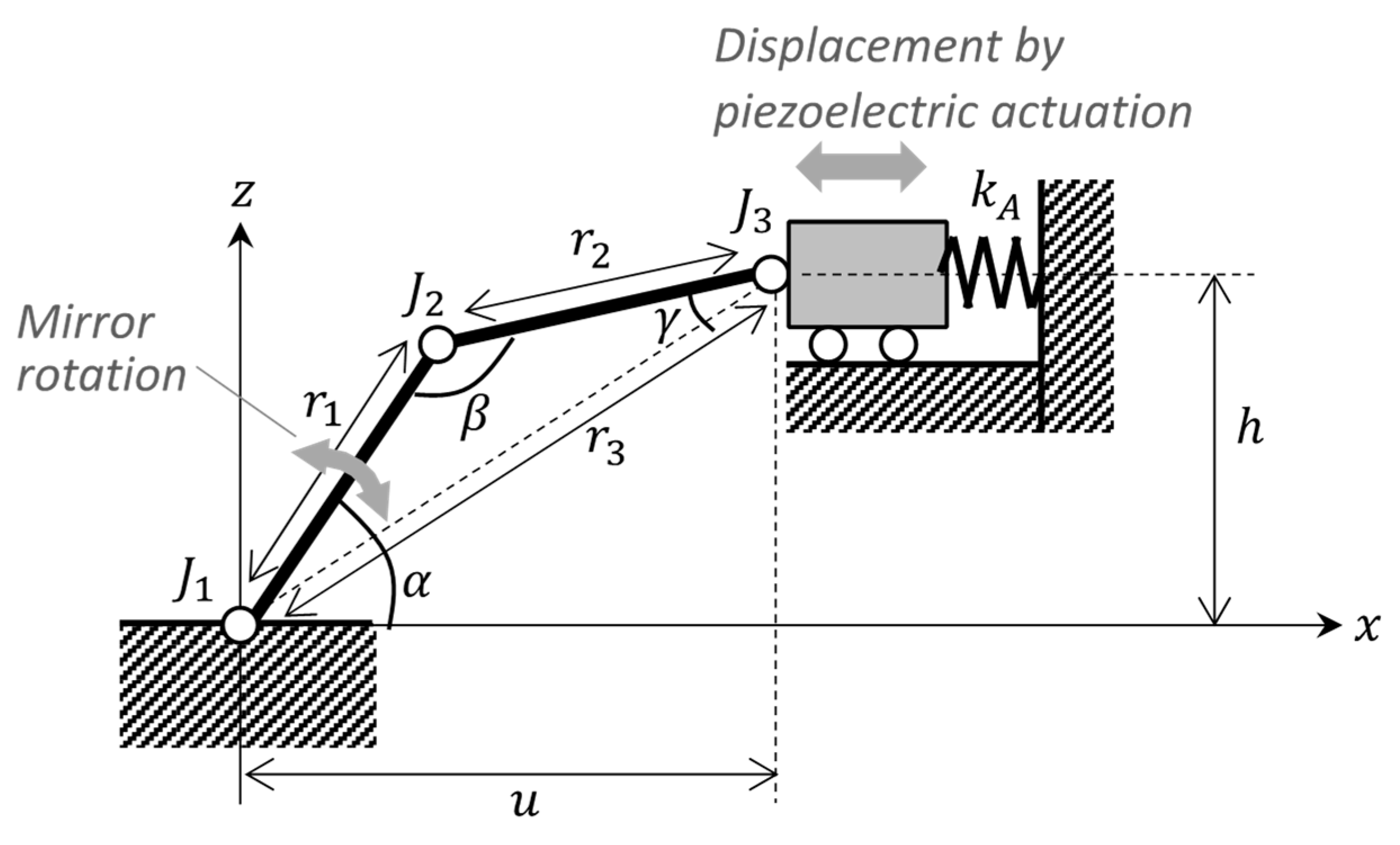
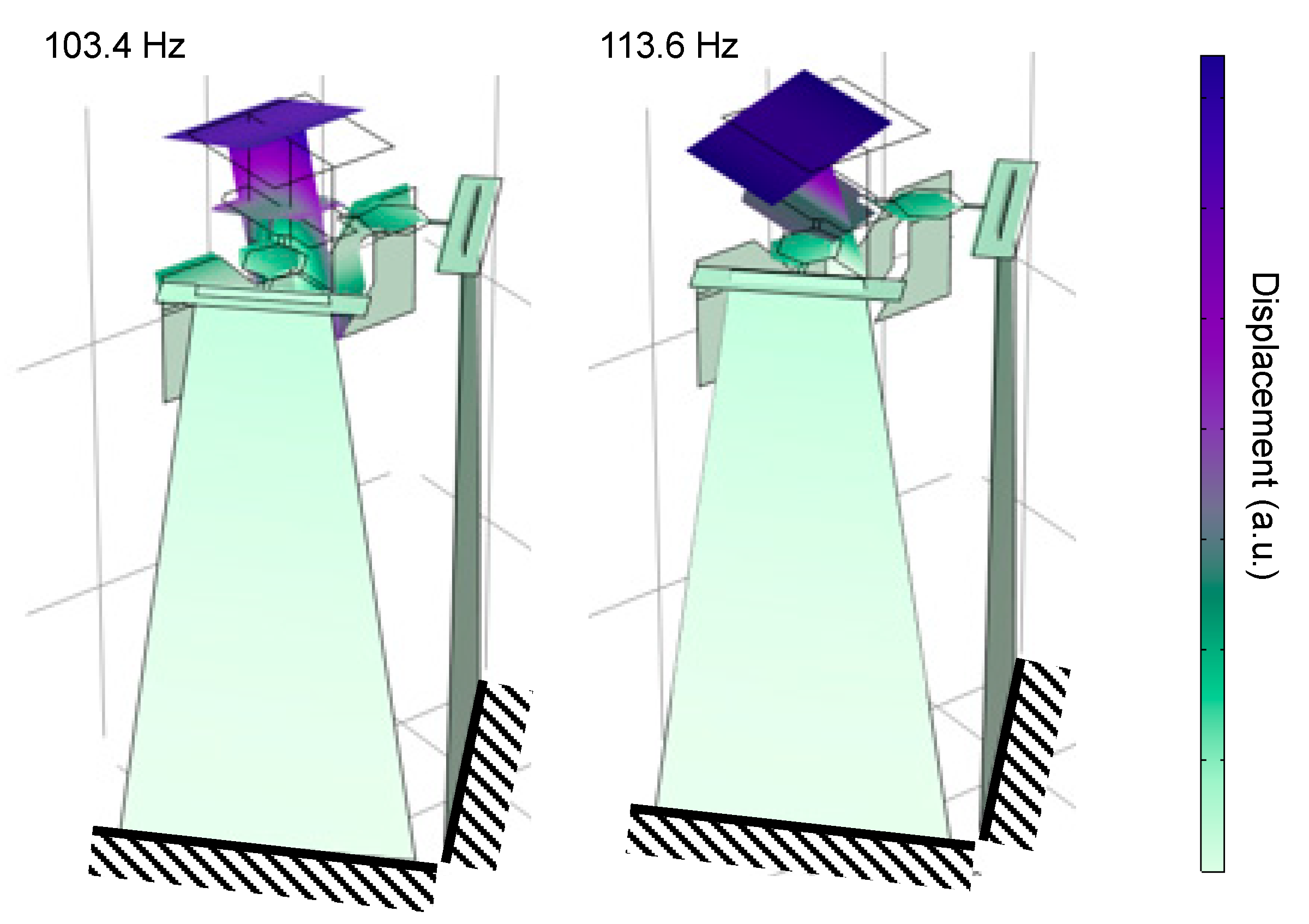
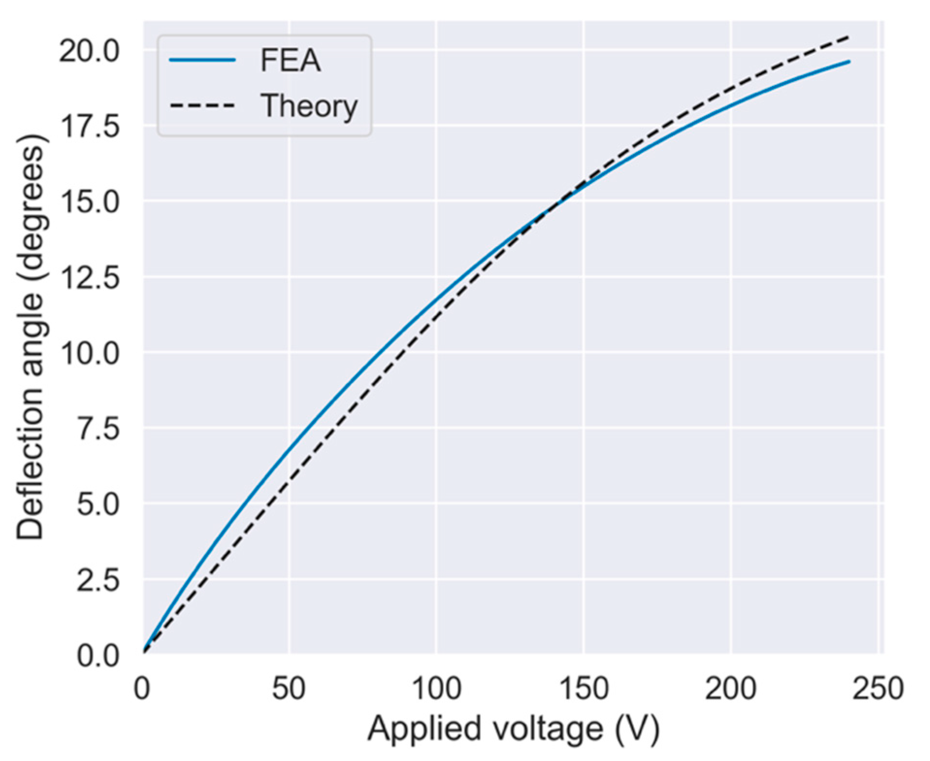
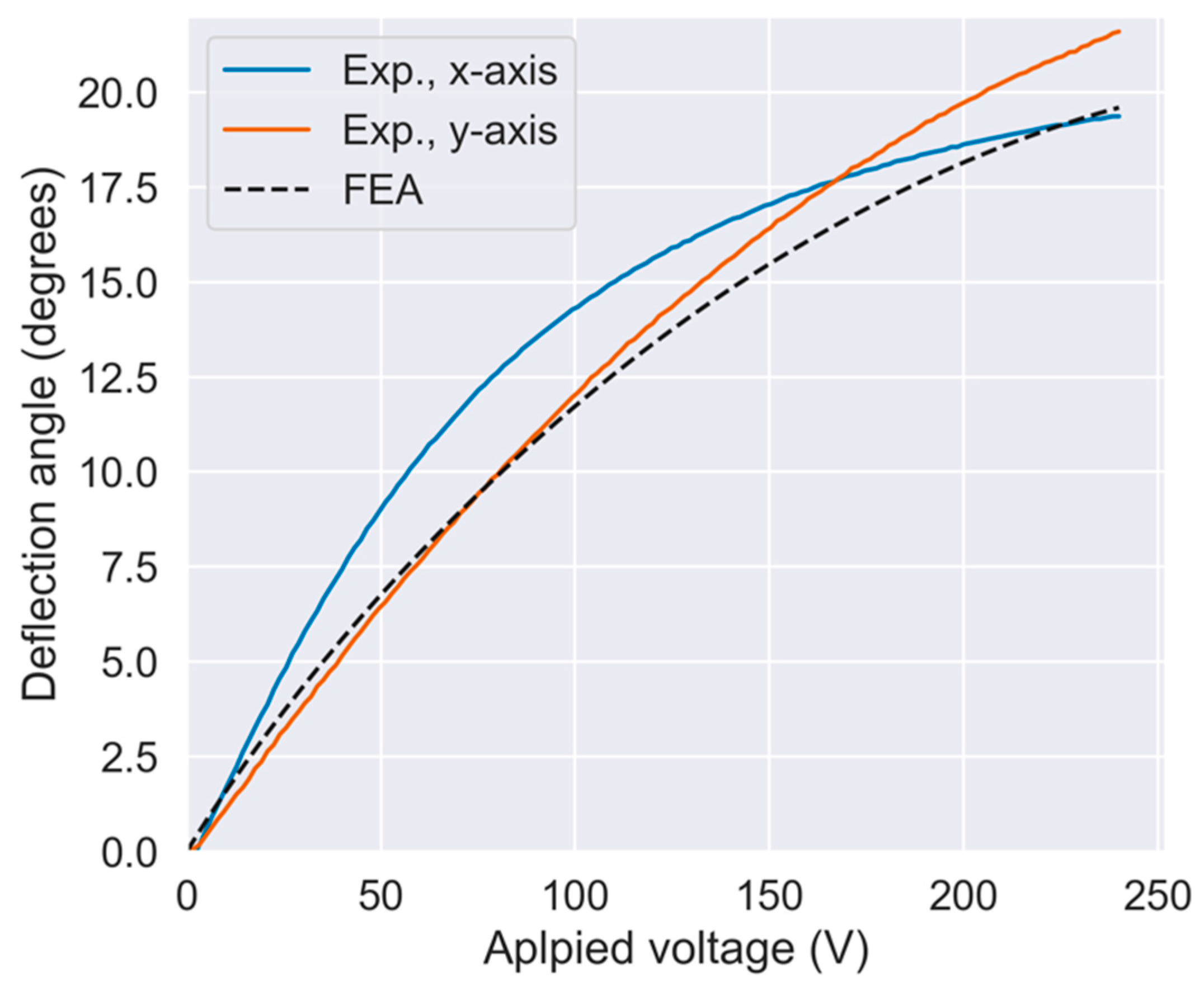
2.2. Performance Analysis
2.3. Materials and Fabrication
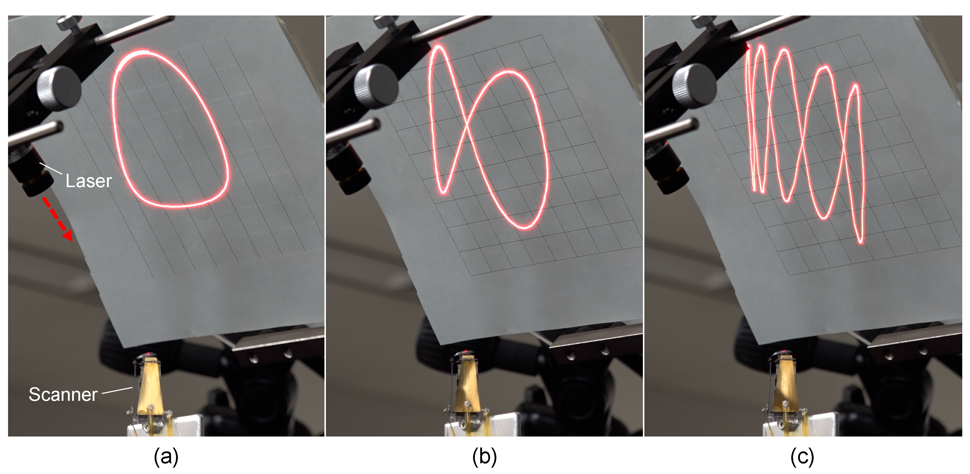
3. Results and Discussion
4. Conclusions
Author Contributions
Funding
Institutional Review Board Statement
Informed Consent Statement
Data Availability Statement
Conflicts of Interest
Appendix A. FEA Model Parameters

| Material | Property | Value |
|---|---|---|
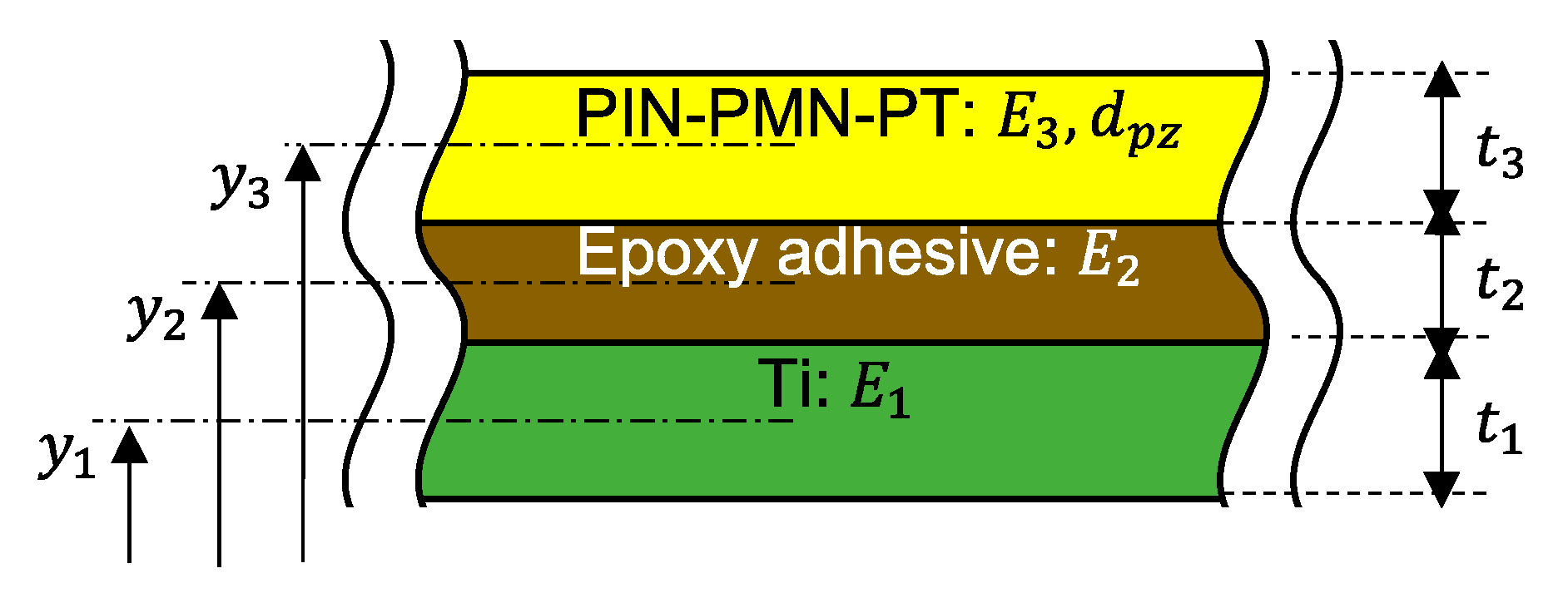
| PIN-PMN-PT | Young’s modulus | 14.3 GPa 1 |
| Density | 8000 kg/m3 | |
| Piezoelectric coefficient | −1156 pm/V | |
| Titanium | Young’s modulus | 116 GPa |
| Density | 4500 kg/m3 | |
| Polyimide | Young’s modulus | 9.0 GPa |
| Density | 1500 kg/m3 | |
| Silicon | Young’s modulus | 160 GPa |
| Density | 2330 kg/m3 |
Appendix B. Hinge Spring Constant and No-Load Deflection Used in the Simplified Theoretical Model
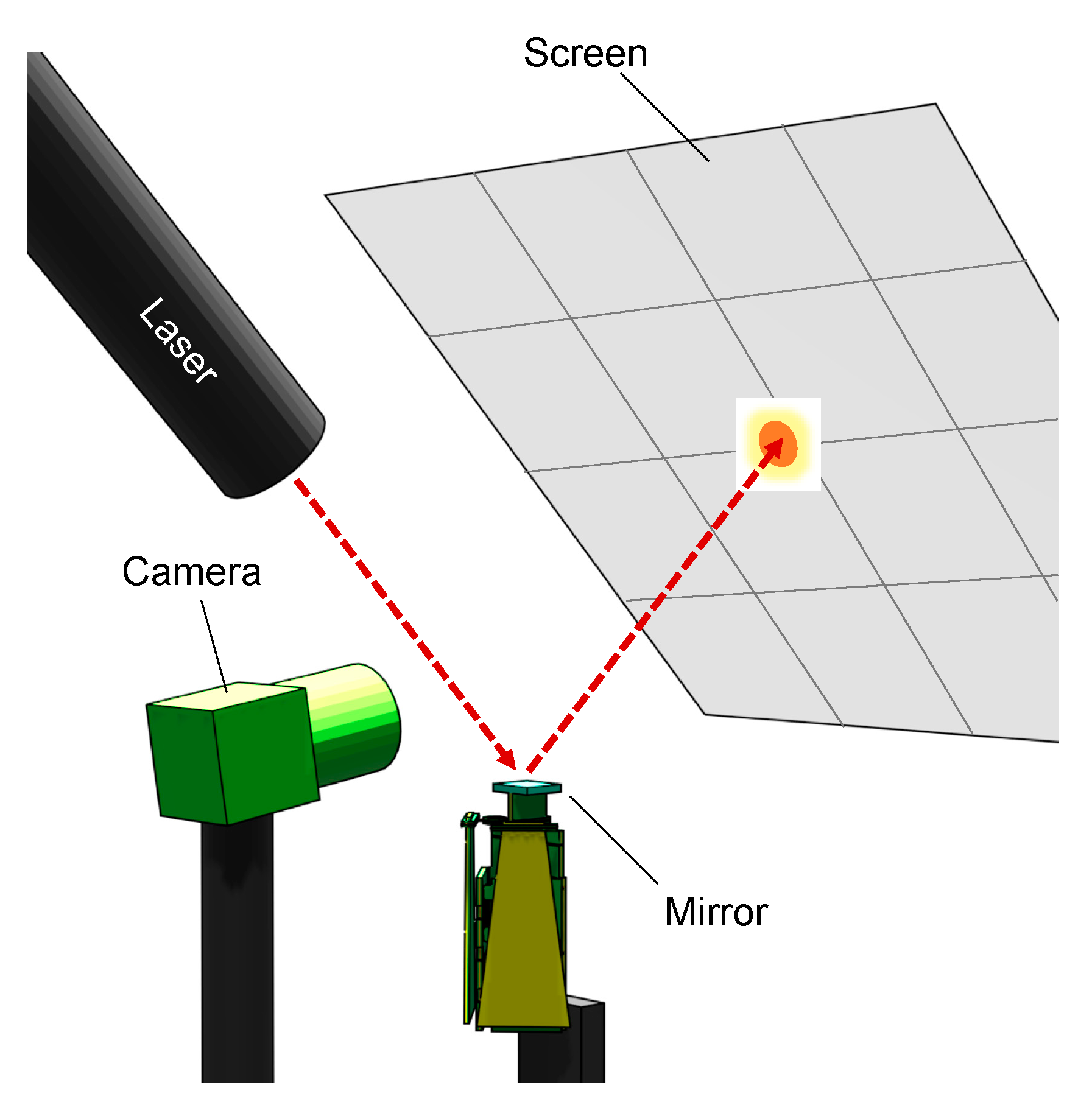
Appendix C. Evaluation Method
References
- Davis, W.O.; Sprague, R.; Miller, J. MEMS-based pico projector display. In Proceedings of the IEEE/LEOS International Conference on Optical MEMS and Nanophotonics, Freiburg, Germany, 11–14 August 2008; pp. 31–32. [Google Scholar]
- Tani, M.; Akamatsu, M.; Yasuda, Y.; Fujita, H.; Toshiyoshi, H. A combination of fast resonance mode and slow static deflection of SOI-PZT actuators for MEMS image projection display. In Proceedings of the IEEE/LEOS International Conference on Optical MEMS and Their Applications, Big Sky, MT, USA, 21–24 August 2006; pp. 25–26. [Google Scholar]
- Iseki, T.; Okumura, M.; Sugawara, T. Shrinking design of a MEMS optical scanner having four torsion beams and arms. Sens. Actuators A 2010, 164, 95–106. [Google Scholar] [CrossRef]
- Baran, U.; Brown, D.; Holmstrom, S.; Balma, D.; Davis, W.O.; Muralt, P.; Urey, H. Resonant PZT MEMS scanner for high-resolution displays. J. Microelectromech. Syst. 2012, 21, 1303–1310. [Google Scholar] [CrossRef] [Green Version]
- Sandner, T.; Klose, M.T.; Schenk, H.; Schwarzer, S.; Hinkov, V.; Hofler, H.; Wolfelschneider, H. 3D imaging using resonant large-aperture MEMS mirror arrays and laser distance measurement. In Proceedings of the IEEE/LEOS International Conference on Optical MEMS and Nanophotonics, Freiburg, Germany, 11–14 August 2008; pp. 78–79. [Google Scholar]
- Makishi, W.; Kawai, Y.; Esashi, M. Magnetic torque driving 2D micro scanner with a non-resonant large scan angle. IEEJ Trans. Sens. Micromech. 2010, 130, 135–136. [Google Scholar] [CrossRef]
- Wang, D.; Strassle, S.; Stainsby, A.; Bai, Y.; Koppal, S.; Xie, H. A compact 3D lidar based on an electrothermal two-axis MEMS scanner for small UAV. Proc. Spie Laser Radar Technol. Appl. 2018, 10636, 106360G. [Google Scholar]
- Tsai, J.; Wu, M.C. A high port-count wavelength-selective switch using a large scan-angle, high fill-factor, two-axis MEMS scanner array. IEEE Photonics Technol. Lett. 2006, 18, 1439–1441. [Google Scholar] [CrossRef]
- Jeon, S.; Toshiyoshi, H. MEMS tracking mirror system for a bidirectional free-space optical link. Appl. Opt. 2017, 56, 6720–6727. [Google Scholar] [CrossRef]
- Kumpulainen, T.; Karjalainen, I.; Prusi, T.; Hölsä, J.; Heikkilä, R.; Tuokko, R. Pulsed Laser Machining Implemented with Piezoelectric Actuator. Int. J. Optomechatronics 2009, 3, 1–17. [Google Scholar] [CrossRef]
- Kim, H.-S.; Lee, D.-H.; Hurl, D.J.; Lee, D.-C. Development of two-dimensional piezoelectric laser scanner with large steering angle and fast response characteristics. Rev. Sci. Instrum. 2019, 90, 065004. [Google Scholar] [CrossRef]
- Piatti, D. State-of-the-Art of TOF Range-Imaging Sensors. In TOF Range-Imaging Cameras; Remondio, F., Stoppa, D., Eds.; Springer: Berlin, Germany, 2013. [Google Scholar]
- Raj, T.; Hashim, F.H.; Huddin, A.B.; Ibrahim, M.F.; Hussain, A. A Survey on LiDAR Scanning Mechanisms. Electronics 2020, 9, 741. [Google Scholar]
- Wang, D.; Watkins, C.; Xie, H. MEMS Mirrors for LiDAR: A Review. Micromachines 2020, 11, 456. [Google Scholar] [CrossRef]
- Milanovic, V. Linearized Gimbal-less Two-Axis MEMS Mirrors. In Proceedings of the Conference on Optical Fiber Communication/International Conference on Integrated Optics and Optical Fiber Communication, San Diego, CA, USA, 22–26 March 2009; p. 19. [Google Scholar]
- Piyawattanametha, W.; Patterson, P.; Hah, D.; Toshiyoshi, H.; Wu, M. Surface-and bulk-micromachined two-dimensional scanner driven by angular vertical comb actuators. J. Microelectromech. Syst. 2005, 14, 1329–1338. [Google Scholar] [CrossRef] [Green Version]
- Whitney, J.P.; Sreetharan, P.S.; Ma, K.Y.; Wood, R.J. Pop-up Book MEMS. J. Micromech. Microeng. 2011, 21, 115021. [Google Scholar] [CrossRef] [Green Version]
- Bonded Mirror Devices—Mirrorcle Technologies Inc. Available online: https://www.mirrorcletech.com/wp/products/mems-mirrors/dual/bonded/ (accessed on 25 March 2021).
- Jain, A.; Xie, H. A single-crystal silicon micromirror for large bi-directional 2D scanning applications. Sens. Actuators A Phys. 2006, 130, 454–460. [Google Scholar] [CrossRef]
- Wang, D.; Zhang, X.; Zhou, L.; Liang, M.; Zhang, D.; Xie, H. An ultra-fast electrothermal micromirror with bimorph actuators made of copper/tungsten. In Proceedings of the 2017 International Conference on Optical MEMS and Nanophotonics (OMN), Santa Fe, NM, USA, 13–17 August 2017; pp. 1–2. [Google Scholar]
- Zhang, X.; Zhou, L.; Xie, H. A Fast, Large-Stroke Electrothermal MEMS Mirror Based on Cu/W Bimorph. Micromachines 2015, 6, 1876–1889. [Google Scholar] [CrossRef]
- Wang, D.; Watkins, C.; Aradhya, M.; Koppal, S.; Xie, H. A Large Aperture 2-Axis Electrothermal MEMS Mirror for Compact 3D LiDAR. In Proceedings of the 2019 International Conference on Optical MEMS and Nanophotonics (OMN), Daejeon, Korea, 28 July–1 August 2019; pp. 180–181. [Google Scholar]
- Iseki, T.; Okumura, M.; Sugawara, T. Two-Dimensionally Deflecting Mirror Using Electromagnetic Actuation. Opt. Rev. 2006, 13, 189–194. [Google Scholar] [CrossRef]
- Wang, J.; Hao, Q.; Song, Y.; Hu, Y. Novel MOEMS-based beam steering method. In Proceedings of the International Conference on Optical Instruments and Technology (OIT2011), Beijing, China, 6 November 2011; p. 81971D. [Google Scholar]
- Ataman, C.; Lani, S.; Noell, W.; De Rooij, N. A dual-axis pointing mirror with moving-magnet actuation. J. Micromech. Microeng. 2012, 23, 25002. [Google Scholar] [CrossRef]
- Chen, S.-L.; Xie, Z.; Ling, T.; Guo, L.J.; Wei, X.; Wang, X. Miniaturized all-optical photoacoustic microscopy based on microelectromechanical systems mirror scanning. Opt. Lett. 2012, 37, 4263–4265. [Google Scholar] [CrossRef]
- Shin, B.H.; Oh, D.; Lee, S.-Y.; Dongho, O. A Two-Dimensional Laser Scanning Mirror Using Motion-Decoupling Electromagnetic Actuators. Sensors 2013, 13, 4146–4156. [Google Scholar] [CrossRef]
- Pollock, C.; Javor, J.; Stange, A.; Barrett, L.K.; Bishop, D.J. Extreme angle, tip-tilt MEMS micromirror enabling full hemispheric, quasi-static optical coverage. Opt. Express 2019, 27, 15318–15326. [Google Scholar] [CrossRef]
- Liu, W.; Zhu, Y.; Jia, K.; Liao, W.; Tang, Y.; Wang, B.; Xie, H. A tip–tilt–piston micromirror with a double S-shaped unimorph piezoelectric actuator. Sens. Actuators A Phys. 2013, 193, 121–128. [Google Scholar] [CrossRef]
- Naono, T.; Fujii, T.; Esashi, M.; Tanaka, S. Non-resonant 2-D piezoelectric MEMS optical scanner actuated by Nb doped PZT thin film. Sens. Actuators A Phys. 2015, 233, 147–157. [Google Scholar] [CrossRef]
- Gu-Stoppel, S.; Lisec, T.; Fichtner, S.; Funck, N.; Eisermann, C.; Lofink, F.; Wagner, B.; Müller-Groeling, A. A highly linear piezoelectric quasi-static MEMS mirror with mechanical tilt angles of larger than 10°. Proc. SPIE 10931 MOEMS Miniat. Syst. 2019, 10931, 1093102. [Google Scholar]
- Wei, C.; Sihai, C.; Dong, L.; Guohua, J. A compact two-dimensional laser scanner based on piezoelectric actuators. Rev. Sci. Instrum. 2015, 86, 013102. [Google Scholar] [CrossRef] [PubMed]
- Sun, E.; Zhang, S.; Luo, J.; Shrout, T.R.; Cao, W. Elastic, dielectric, and piezoelectric constants of Pb(In1/2Nb1/2)O3–Pb(Mg1/3Nb2/3)O3–PbTiO3 single crystal poled along [011]c. Appl. Phys. Lett. 2010, 97, 032902. [Google Scholar] [CrossRef] [PubMed] [Green Version]
- Ozaki, T.; Ohta, N.; Fujiyoshi, M. Hot laminatino and origami assembly fabrication of miniaturized compliant mechanism. MethodsX 2021, 8, 101458. [Google Scholar] [CrossRef]
- Kobayashi, T.; Oyama, S.; Okada, H.; Makimoto, N.; Tanaka, K.; Itoh, T.; Maeda, R. An Electrostatic Field Sensor Driven by Self-Excited Vibration of Sensor/Actuator Integrated Piezoelectric Micro Cantilever. In Proceedings of the 2012 IEEE 25th International Conference on Micro Electro Mechanical Systems (MEMS), Paris, France, 29 January–2 February 2012. [Google Scholar]
- Zhang, Z.; Kan, J.; Cheng, G.; Wang, H.; Jiang, Y. A Piezoelectric Micropump with an Integrated Sensor Based on Space-Division Multiplexing. Sens. Actuators A Phys. 2013, 203, 29–36. [Google Scholar] [CrossRef]
- Fu, J.; Zhou, X.; Li, F. An Adaptive Nanoindentation System Based on Electric Bending of a Piezoelectric Cantilever. Sens. Actuators A Phys. 2014, 216, 249–256. [Google Scholar] [CrossRef]
- Ozaki, T.; Hamaguchi, K. Electro-Aero-Mechanical Model of Piezoelectric Direct-Driven Flapping-Wing Actuator. Appl. Sci. 2018, 8, 1699. [Google Scholar] [CrossRef] [Green Version]


| Parameter | Value | Unit |
|---|---|---|
| 2.72, 3.40, 5.62 | mm | |
| 8.04, 4.69, 4.69 | Nm/rad | |
| 167 | N/m | |
| mm/V |
| Ref. | Actuation Principle | Mirror Area (mm2) | Deflection Angles (degrees) | Resonant Frequencies (Hz) | FoM (mm·rad·kHz) |
|---|---|---|---|---|---|
| [15] | Electrostatic | 0.50 | 12.0 | 3800, 3900 | 1.29 |
| [15] | 2.0 | 12.0 | 670, 1600 | 0.76 | |
| [16] | 0.79 | 12.4, 8.2 | 350, 320 | 0.12 | |
| [18] | 19.6 | 10.4 | 278 | 0.50 | |
| [18] | 32.2 | 5.56, 5.64 | 339, 337 | 0.42 | |
| [18] | 44.2 | 2.49, 2.49 | 559, 557 | 0.37 | |
| [19] | Thermal | 0.52 | 20.0 | 690, 740 | 0.41 |
| [20] | 0.20 | 2.0 | 12800 | 0.45 | |
| [21] | 0.81 | 18.0 | 550 | 0.35 | |
| [22] | 5.0 | 7.5, 6.0 | 615 | 0.37 | |
| [19] | 0.25 | 51.0, 39.5 | 170, 870 | 0.46 | |
| [23] | Electromagnetic | 4.9 | 30.0, 23.0 | 160, 210 | 0.43 |
| [24] | 9.0 | 10.0 | 130, 120 | 0.15 | |
| [25] | 16.0 | 16.0 | 160, 170 | 0.42 | |
| [26] | 13.4 | 8.0 | 240, 390 | 0.36 | |
| [27] | 64.0 | 7.85, 8.10 | 60 | 0.15 | |
| [28] | 0.11 | 120 | 70 | 0.11 | |
| [29] | Piezoelectric | 1.2 | 2.1, 1.8 | 195 | 0.0082 |
| [30] | 0.79 | 9.3 | 1370 | 0.44 | |
| [31] | 0.50 | 12.5 | 900 | 0.087 | |
| This work | 36.0 | 21.6, 19.4 | 89, 111 | 0.48 |
Publisher’s Note: MDPI stays neutral with regard to jurisdictional claims in published maps and institutional affiliations. |
© 2021 by the authors. Licensee MDPI, Basel, Switzerland. This article is an open access article distributed under the terms and conditions of the Creative Commons Attribution (CC BY) license (https://creativecommons.org/licenses/by/4.0/).
Share and Cite
Ozaki, T.; Ohta, N.; Fujiyoshi, M. Wide Two-Degree-of-Freedom Static Laser Scanner with Miniaturized Transmission Mechanism and Piezoelectric Actuation. Sensors 2021, 21, 6077. https://doi.org/10.3390/s21186077
Ozaki T, Ohta N, Fujiyoshi M. Wide Two-Degree-of-Freedom Static Laser Scanner with Miniaturized Transmission Mechanism and Piezoelectric Actuation. Sensors. 2021; 21(18):6077. https://doi.org/10.3390/s21186077
Chicago/Turabian StyleOzaki, Takashi, Norikazu Ohta, and Motohiro Fujiyoshi. 2021. "Wide Two-Degree-of-Freedom Static Laser Scanner with Miniaturized Transmission Mechanism and Piezoelectric Actuation" Sensors 21, no. 18: 6077. https://doi.org/10.3390/s21186077
APA StyleOzaki, T., Ohta, N., & Fujiyoshi, M. (2021). Wide Two-Degree-of-Freedom Static Laser Scanner with Miniaturized Transmission Mechanism and Piezoelectric Actuation. Sensors, 21(18), 6077. https://doi.org/10.3390/s21186077