Abstract
To meet the increasing demands for remote sensing, a number of radar systems using Linear Frequency Modulation (LFM) waveforms have been deployed, causing the problem of depleting frequency resources. To address this problem, several researchers have proposed the Spectrum Shared Radar System (SSRS) in which multiple radars share the same frequency band to transmit and receive their own signals. To mitigate the interferences caused by the signal transmission by other radars, SSRS employs orthogonal waveforms that inherit the orthogonality of the waveforms from orthogonal codes. However, the inherited orthogonality of the codes is significantly reduced when incorporating LFM waveforms with the codes. To solve this problem, in this paper, we propose a novel but simple scheme for generating a set of optimized coded LFM waveforms via new optimization framework. In the optimization framework, we minimize the weighted sum of autocorrelation sidelobe peaks () and cross-correlation peaks () of the coded LFM waveforms to maximize the orthogonality of the waveforms. Through computer simulations, we show that the waveforms generated by the proposed scheme outperform the waveforms created by previous proposals in terms of and .
1. Introduction
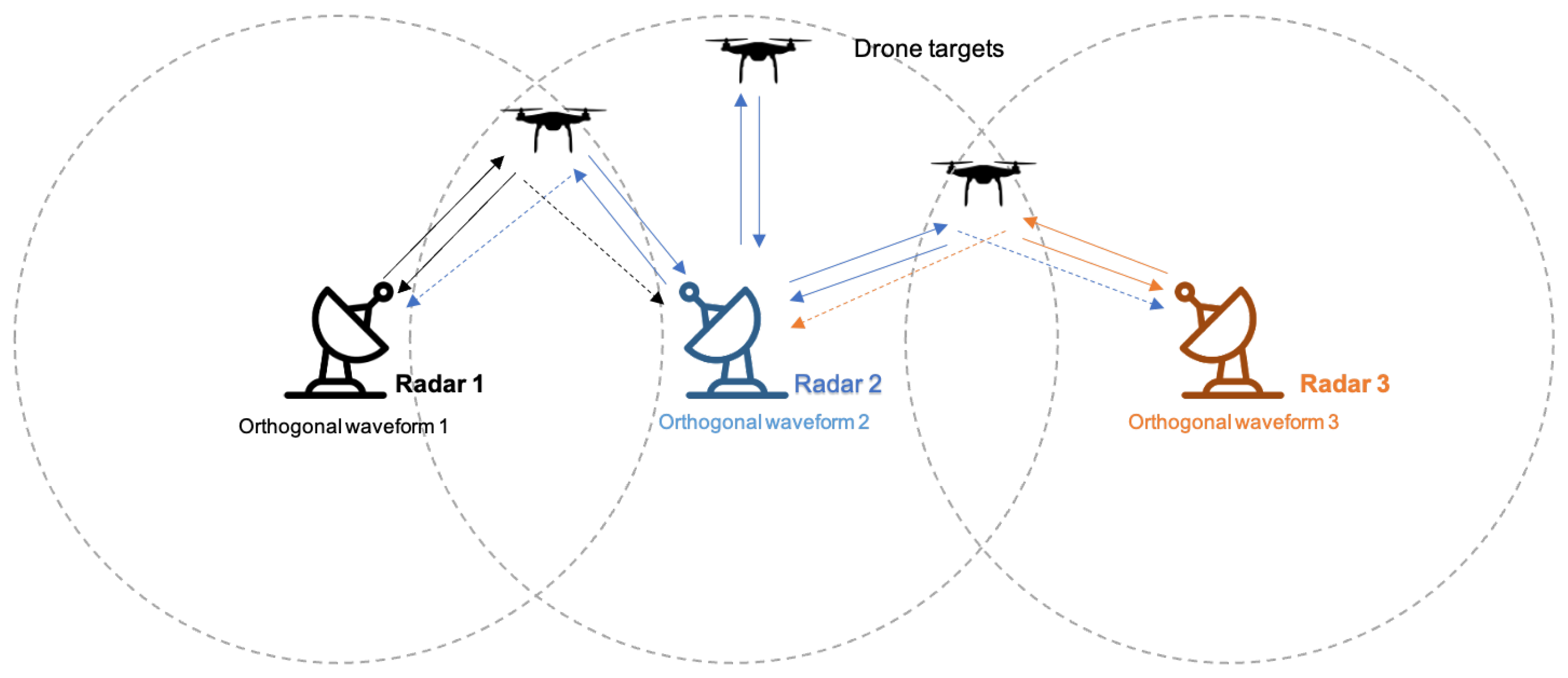
A Linear Frequency Modulation (LFM) waveform is the most popular type of pulse compression and has been adopted for many radar systems due to its ease of hardware implementation and good range resolution. However, due to the increasing demands for mobile communications and remote sensing, a frequency resource that could be allocated to the radar systems and that employs an LFM waveform is lacking. To remedy this issue, many researchers have proposed the use of orthogonal waveforms in modern radar systems. The representative system adopting orthogonal waveforms is the Spectrum Shared Radar System (SSRS), where multiple radars in close proximity share the same frequency band as depicted in Figure 1 [1,2,3]. To estimate a target’s characteristics accurately in the SSRS, each radar must operate independently using a waveform that does not interfere with other radar signals. For this purpose, it is imperative to design orthogonal waveforms that minimize the interferences.
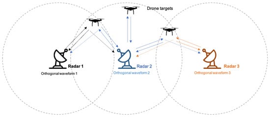
Figure 1.
Spectrum Shared Radar System.
A simple solution to minimize interference in SSRS is a time division approach. In this approach, only one radar transmits a waveform and receives an echo signal during one time period; after the period, one of the other radars operates in a given order. The limitation of this approach lies in the low utilization, which means that the other radars must wait until the operation of one radar is completed. The low utilization inevitably hinders the real-time detection and estimation of a target’s characteristics, such as its position and velocity.
To address the limitations of the time division approach, several researchers have employed orthogonal codes to generate orthogonal radar waveforms. H. Deng proposed an optimization framework for generating a polyphase code set through the hybrid optimization process [4]. Specifically, we can derive a polyphase code set that minimizes the autocorrelation sidelobe peak () and cross-correlation peak () via the optimization framework. In [5], U. Majumder et al. proposed the incorporation of an orthogonal code (e.g., Walsh–Hadamard code) into the Linear Frequency Modulation (LFM) waveforms via Spread Spectrum Coded LFM (SSCL). Specifically, an orthogonal waveform is created by multiplying an LFM waveform with each element of an orthogonal code. Even if the method for creating the SSCL waveform is simple, this method has a limitation in that multiplication with the rapidly fluctuated LFM waveform could significantly reduce the orthogonality of the code.
To address the problem mentioned above, we propose a novel but simple scheme for creating a set of orthogonal LFM waveforms that maximizes the orthogonality of the coded LFM waveforms. Here, the coded LFM waveform refers to an LFM signal encoded with a code. To maximize the orthogonality, our scheme employs a new optimization framework whereby we optimize coded LFM waveforms rather than orthogonal codes. In previous approaches, an orthogonal code set was firstly derived through an optimization framework (or the well-known orthogonal code was used) and then each code was multiplied with an LFM waveform. In contrast, we derive a set of orthogonal coded LFM waveforms through the proposed optimization framework. The beauty of the proposed scheme lies in the improvement of the orthogonality while benefiting from all the advantages of the LFM and an orthogonal code set. Our simulation results shows that our scheme exhibits significant performance improvements over the scheme proposed in [5]. This improvement comes from (1) the new optimization framework for generating optimized coded LFM waveforms and (2) a polyphase code with a higher degree of freedom compared to Walsh–Hadamard code.
We analyze the impact of several parameters (e.g., the number of distinct phases, the length of the code, and the number of radars) on the orthogonality of radar waveforms using computer simulations. Moreover, we observe that the proposed optimized coded LFM outperforms the waveform of [5] by up to 11.652 dB and 17.560 dB in terms of and , respectively. The contributions in this paper are as follows:
- We propose a scheme for designing a set of optimized coded LFM waveforms to improve the orthogonality of previous proposals;
- The set of optimized coded LFM waveforms provides optimized orthogonality while inheriting various advantages of LFM;
- We propose an optimization framework for deriving the proposed optimal coded LFM waveforms;
- We conduct an in-depth study of the proposed optimal coded LFM waveforms through computer simulations and show that the proposed coded LFM waveforms outperform the orthogonal waveforms in previous proposals.
The remainder of this document is structured as follows. Section 2 briefly introduces the related works on orthogonal waveform design and highlights their limitations. In Section 3, we describe the details of the proposed scheme. Section 4 presents the simulation results and performance evaluations in terms of orthogonality in relation to and . Numerical results and a discussion are provided in Section 5. Finally, Section 6 summarizes the results and draws conclusions.
2. Related Works
To maximize the system utilization in the SSRS, several researchers have proposed a mechanism for deriving an orthogonal waveform set by leveraging phase code diversity and chirp modulation diversity. Deng exploited phase code diversity to design an orthogonal polyphase code set that has good and using a hybrid optimization process that leverages simulated annealing and the traditional iterative code selection method [4]. Afterwards, the authors in [6,7] adopted a genetic algorithm and the Niche genetic algorithm in the optimization process to improve the orthogonality of the code sets. In [8], the authors revealed a problem that the method could be trapped in the local minimum shortly after initialization, which resulted in poor performance when designing a polyphase waveform. To solve this problem, the authors proposed a relaxation and cyclic optimization algorithm.
Several researchers have proposed the use of chirp diversity to generate orthogonal waveforms [9,10,11,12,13,14]. Welstead studied the relationship between the chirp rate and the level of interferences between two LFM signals with the same pulse width and showed that, as the difference of the chirp rates of two LFM waveforms increases, they become less correlated [9]. Focusing on the characteristics of the chirp rate diversity of a single LFM signal, in [9,10], a method for suppressing cross-term interference using a modified LFM signal composed of multiple sub-chirp signals with different chirp rates was implemented. However, when two signals with the same pulse width have different chirp rates, the bandwidth of one signal is wider than that of the other signal. Like [10], in [11,12,13,14], the authors exploited chirp diversity to generate orthogonal waveforms using a signal composed of several sub-chirps with different chirp rates. Unlike previous studies [9,10], the authors in [11,12,13,14] exploited chirp diversity, but bounded the bandwidth so that all signals had the same bandwidth. In [11], the author developed a waveform consisting of up-chirps and down-chirps within the bounded bandwidth and repeated the waveform within the pulse width. The method for developing a waveform in [11] showed very good cross-correlation performance between a pair of waveforms with different chirp rates. However, the performance in terms of the autocorrelation sidelobe peaks of the waveform was unsatisfactory. The authors in [12,13] constructed a new class of a polyphase code set called piecewise LFM by concatenating the P3/P4 polyphase codes; they examined the autocorrelation side lobe peak and cross-correlation peak performance as well as the Doppler property. This piecewise LFM waveform is composed of several sub-chirps with different chirp rates and sub-chirp durations. Each sub-chirp is configured to occupy an independent bandwidth that does not overlap with other sub-chirps within the specified piecewise LFM bandwidth. In this manner, several orthogonal waveforms can be generated by controlling different sub-chirp durations and chirp rates. Compared to [4], this waveform showed good Doppler properties; however, the performance in terms of autocorrelation and cross-correlation was not significantly improved.
Multiple diversities have been considered for the design of a set of orthogonal waveforms. U. Majumder proposed a scheme for designing SSCL (Spread Spectrum Coded LFM) waveforms that include code diversity and chirp rate diversity [5]. These waveforms are generated by generating LFM signals with different chirp rates (chirp rate diversity) and encoding the LFM signals with an orthogonal code set (code diversity). However, the previous approach for generating a SSCL waveform [5] might reduce the orthogonality of the orthogonal code because each element of the code could be distorted when multiplied with a LFM waveform. To address this issue, we propose a scheme for deriving a set of optimized coded LFM waveforms that maximizes orthogonality. We elaborate on the proposed scheme in the following section.
Instead of designing orthogonal waveforms, several studies have focused on improving orthogonal waveforms by using a pulse train or modifying a matched filter. In [15], the authors mentioned the range–Doppler ambiguity problem of several optimal waveforms and proposed a method to generate optimal frequency-modulated pulse trains to alleviate this problem. In [16], an orthogonal waveform called DFCCW was implemented. The sub-pulses of the waveform proposed in [16] had different carriers and chirp rates, indicating that they had more degrees of freedom to control the waveform properties. This method has been proven to be excellent in reducing cross-ambiguity peaks because of the pulse train property. In [17], the authors showed that high recurrent Doppler sidelobes caused serious interference between channels. To suppress these recurrent side-lobes, they proposed a modified range–Doppler processing method at the receiver.
3. Proposed Scheme
To derive a set of optimized coded LFM waveforms, our scheme employs a new optimization framework in which we find L coded LFM waveforms minimizing an objective function, which is the weighted sum of and . Hence, to understand the process of deriving a set of optimized coded LFM waveforms, we first explain the LFM signal and the set of polyphase codes used to encode the LFM signal. Then, we explain how to find a set of optimized coded LFM waveforms through the proposed optimization process. Before explaining the details, we summarize the nomenclature of this paper in Table 1.

Table 1.
Nomenclature.
3.1. LFM Waveform
An LFM waveform is a signal in which a frequency increases (up-chirp) or decreases (down-chirp) linearly with time, and the LFM waveform is obtained by
where , , and are the pulse width, starting frequency, and chirp rate, respectively. is an indicator function and is expressed as follows.
When the starting frequency is zero, Equation (2) can be simplified as follows.
An LFM waveform set, , consists of L LFM waveforms and is defined as follows (each LFM waveform in might have different chirp rates. If this is the case, a modified LFM signal such as a concatenated LFM or piecewise LFM could be used to make the bandwidth of each LFM signal the same. In this case, chirp rate perturbation can be activated in addition to phase perturbation in the optimization process):
where is the transposition of a vector .
3.2. Polyphase Code Set
To generate a coded LFM waveform, we employ a polyphase code sequence that allows a higher degree of freedom in our optimization process than a well-known binary code set (e.g., Barker code, Walsh–Hadamard code, Gold sequence), leading to better orthogonality (instead of a polyphase code set, other code sets can be used without any modifications in our design). A polyphase code set is composed of L codes; each code includes N sub-pulses elements. The polyphase code set is defined as follows:
where is a code l and is the nth element of , which can be expressed by
and
where is the phase of . It is noted that the nth element of code l is used to encode the nth sub-pulse of coded waveform l. can be selected from the following admissible values:
where M is the number of distinct phases in a code.
3.3. Coded LFM Waveform
The lth coded LFM waveform, , can be generated by multiplying the lth LFM waveform and lth code sequence and can be defined as
where is the chip time of a code sequence. is generally shorter than the pulse time, , and is defined as . That is, the original pulse is split into N sub-pulses, and each code element of the generated code sequence is encoded in each sub-pulse. We briefly define Equation (9) as
A set of coded LFM waveforms, , consists of L coded LFM waveforms as follows:
where is an element operation of ⊙ between and .
3.4. Optimization Framework
If is first optimized and then generates a coded LFM waveform based on the optimized , the orthogonality of would be degraded. As a solution to this problem, we propose a new optimization framework in which we find a set of optimized coded LFM waveforms, , that minimizes an objective function; that is, the weighted sum of and . As we do not vary an LFM waveform set in this optimization framework, finding is comparable to finding . Hence, we use as a configurable parameter of our optimization framework. Through this approach, we can maximize the orthogonality of coded LFM waveforms, which are actually transmitted by radar.
The optimization problem can be formulated as follows:
where is an objective function when a set of coded LFM waveforms is . can be expressed by
where is a weighting factor (it is noted that the increase in means that we design a set of coded LFM waveforms to mitigate more aggressively than ), and and are the autocorrelation sidelobe peak and cross-correlation peak, respectively. and are described by
where k and are the time delay and normalized main lobe width of the ith coded LFM waveform, respectively. is a cross-correlation function of the ith and jth coded LFM waveforms and is an autocorrelation function of the ith coded LFM waveform. can be expressed by
where is the nth element of a discrete sequence for and is a complex conjugate of y. can be easily obtained by replacing with . In radar systems adopting coded waveforms and matched filtering, the autocorrelation sidelobe (i.e., ) might induce a spurious peak, causing false alarms in target detection. Thus, maximizing is comparable to minimizing . As it is impossible to minimize both and in the optimization framework, we minimize the weighted sum of and in our optimization framework. Similar to [13], the main lobe width can be obtained by
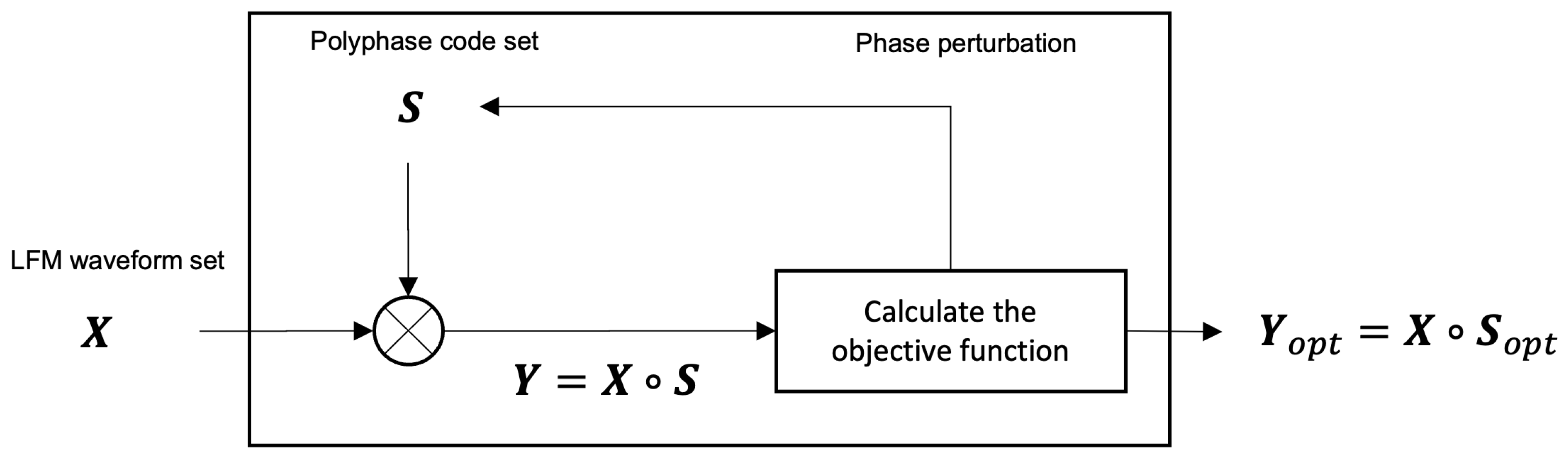
As depicted in Figure 2, the procedure for finding consists of six steps (notably, even if it seems that finding is computationally complex, the complexity of finding in this framework is comparable to the complexity of finding [6]). Specifically, we adopt simulated annealing (SA), as presented in [4], as an algorithm for finding an optimal point, which corresponds to steps 3–6. The detailed procedure is explained below.

Figure 2.
Structure of proposed coded LFM scheme.
- Generate an LFM waveform set, ;
- Generate a random polyphase code set ;
- Generate a set of coded LFM waveforms, ;
- Calculate the objective function, . Then, is adopted as a candidate of the optimized coded LFM waveform. If is smaller than , and are replaced with the current and . Otherwise, we do not change and (any global optimization algorithm (e.g., brute force, simulated annealing, the genetic algorithm, Bayesian optimization, etc.) can be used in this step to find the optimal state. In this paper, we employ simulated annealing (SA), which was also adopted by [4]. In simulated annealing, the transition, which corresponds to the update of the phase matrices and in our context, is determined by an acceptable probability function that depends on the scores of the two states and a global time-varying parameter T called temperature. If a random value p, where is a uniform distribution between 0 and 1, is less then , then the transition is accepted for the current state, , as a candidate of the optimized coded LFM waveform, . This probability prevents the algorithm from becoming stuck at a local minimum that is worse than the global minimum. Please refer to [4] for detailed operation);
- In the phase perturbation process, a randomly selected element in is replaced with a different admissible phase, which is defined in Equation (8);
- Repeat steps 3 to 5 until the stop condition is satisfied (we use the stop conditions adopted by [4]. If the phase perturbation is not accepted during three consecutive temperature reductions in the simulated annealing algorithm, then the optimization process is stopped).
4. Performance Evaluation
In this section, we present the evaluation of the proposed scheme for generating a set of optimized coded LFM waveforms using MATLAB R2020b [18]. More specifically, we obtained two performance measures to evaluate the orthogonality (i.e., and ) as a function of several independent variables: the code length (N), the number of distinct phases (M), the weighting factor (), and the number of radars (L). As the optimization process is a task to find a phase matrix , we selected L, M, and N to constitute the phase matrix as independent variables, and was used for the objective function. The chirp bandwidth and pulse width were fixed to 16 MHz and 1 s, respectively (the netted radar system for detecting drones normally consists of up to 8 radars and uses the same pulse length of 1 to perform the same role [19] and 16 MHz, respectively). The sampling rate used in the MATLAB simulation was set to 256 MHz. The bandwidth of the coded LFM is determined by the sum of the bandwidth of the LFM waveform (B) and the bandwidth of the code (). This sampling rate satisfies the Nyquist bandwidth for the bandwidth of the coded LFM waveform used in the experiment.
To obtain a set of optimized coded LFM waveforms in this evaluation, we adopted a hybrid optimization process similar to [4]. To demonstrate the superiority of the proposed scheme, we compared the orthogonality of the proposed optimized coded LFM waveforms with that of SSCL waveforms [5]. In the SSCL waveforms, we generated two types of coded waveforms: (1) SSCL waveforms encoded with the Walsh–Hadamard code (SSCL–Hadamard) and (2) SSCL waveforms encoded with the polyphase codes derived in [4] (SSCL–Polyphase). The setting of default parameters is shown in Table 2.
Table 2.
Parameter settings.
4.1. Impact of the Number of Radars
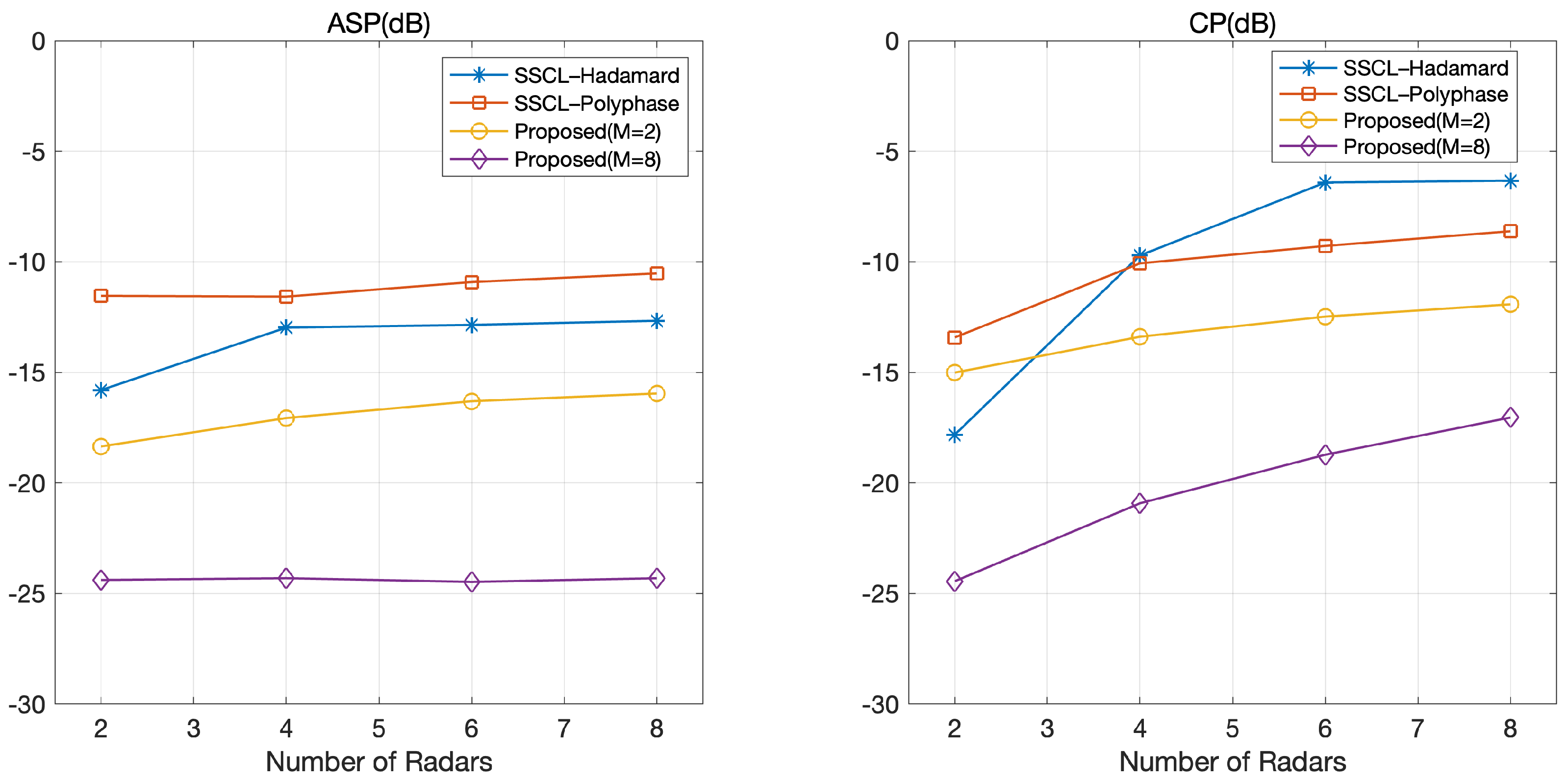
Figure 3 depicts and according to the number of radars. We observe that the and of the proposed optimized coded LFM waveforms were lower than those of the SSCL–Hadamard and SSCL–Polyphase waveforms. This was because the objective function of the proposed optimization framework was a function of coded LFM waveforms. In contrast, the objective function for obtained SSCL–Hadamard and SSCL–Polyphase waveforms was based on orthogonal codes, where orthogonality could be degraded during multiplication with LFM waveforms.
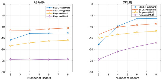
Figure 3.
and according to the number of radars.
Figure 3 shows that and increased with the number of radars in both the proposed coded LFM waveforms and two benchmarks (SSCL–Hadamard and SSCL–Polyphase). This was because it was unlikely that a set of waveforms would be selected that could produce good orthogonality for all pairs of waveforms as L increased. Moreover, in Figure 3, an additional gain was obtained by increasing the number of distinct phases in the proposed LFM waveforms.
4.2. Impact of Code Length
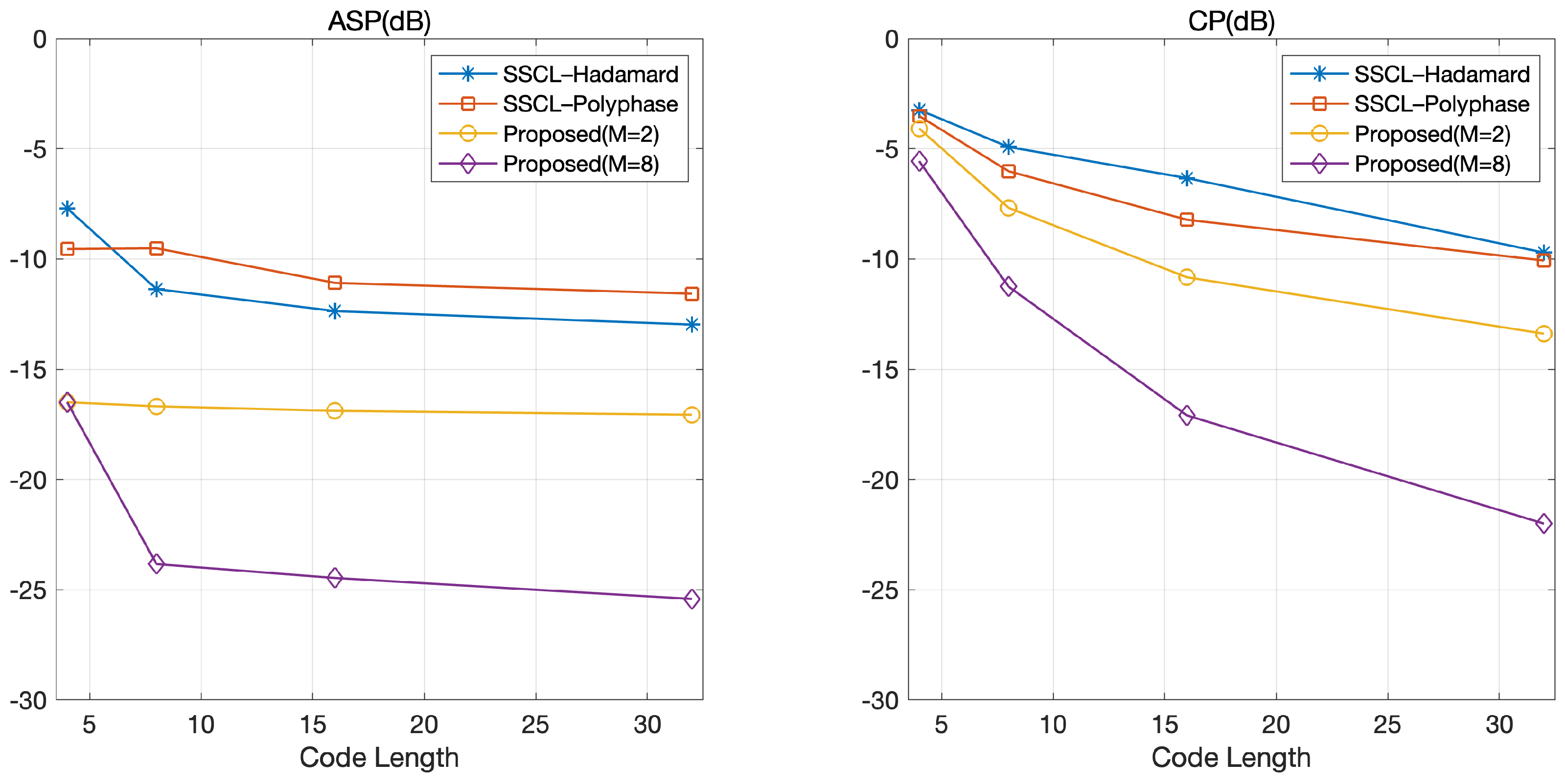
Figure 4 shows and according to the code length. As expected, the optimized coded LFM waveform outperformed the SSCL–Hadamard and SSCL–Polyphase waveforms in terms of and . Similar to Figure 3, Figure 4 shows that the additional gain could be obtained by selecting a large M in the proposed optimized coded LFM waveform. Specifically, decreased exponentially with the code length and was likely to converge with the code length. From this observation, we conclude that the code length is a dominant factor affecting the orthogonality. This is because the degree of freedom (DoF) increases exponentially with the code length, which implies that we can select a set of coded waveforms with large orthogonality in the optimization process. From Figure 4, we learn that an appropriate tradeoff is required between the bandwidth of a radar system and the code length satisfying the orthogonal performance in the proposed scheme. Specifically, the bandwidth of the waveform increases linearly with the code length, but the gains in and tend to gradually decrease with the code length, as depicted in Figure 4. This implies that a longer code length allows the orthogonal gain to be achievable with a greater number of phases.
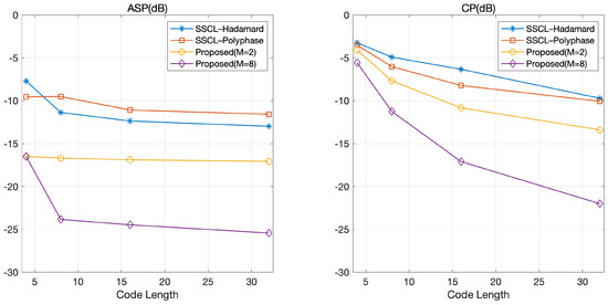
Figure 4.
and according to the code length.
4.3. Impact of the Number of Distinct Phases
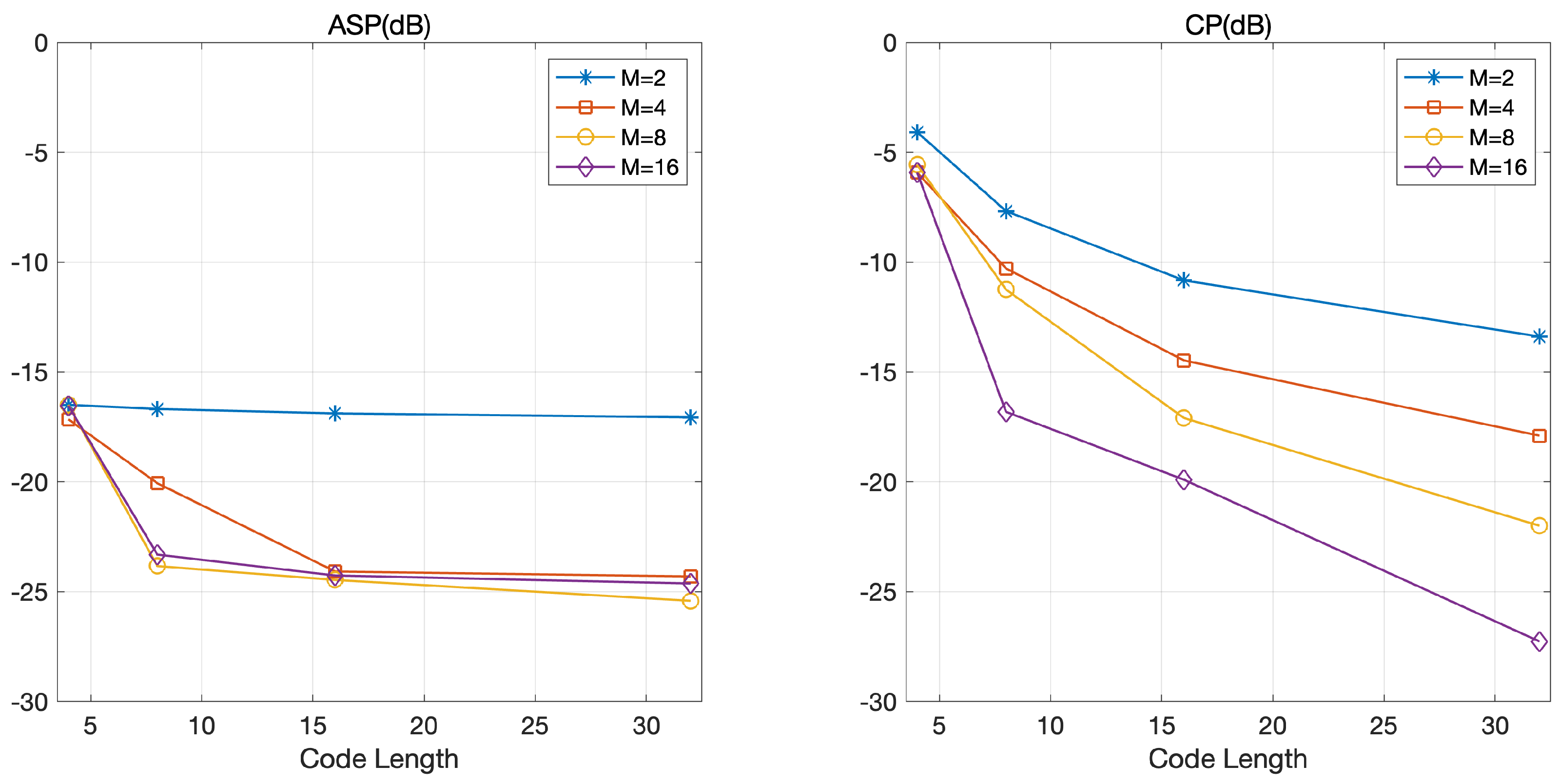
Figure 3 and Figure 4 confirm that our scheme could generate a better set of orthogonal waveforms than the two benchmarks. We expected that we could further improve the orthogonal waveforms of our scheme by controlling the number of distinct phases. To confirm this, we evaluated the and of the proposed optimized LFM waveforms according to the number of distinct phases. Figure 5 shows that both and decreased with the number of distinct phases. In particular, the gain induced by adopting a large M increased with the code length N. This phenomenon resulted from the fact that the degree of freedom (DoF) in the optimization process increased exponentially with N (the number of coded LFM waveforms that could be selected in the optimization process was ).
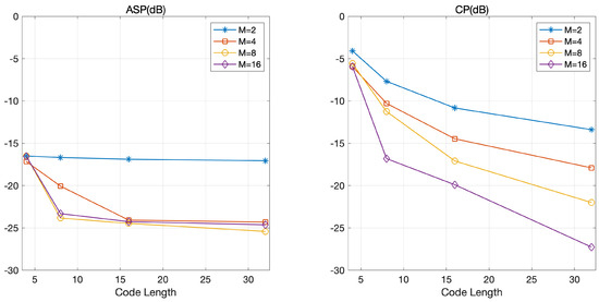
Figure 5.
and according to the code length in various settings for M: , 4, 8, and 16.
4.4. Impact of the Weighting Factor
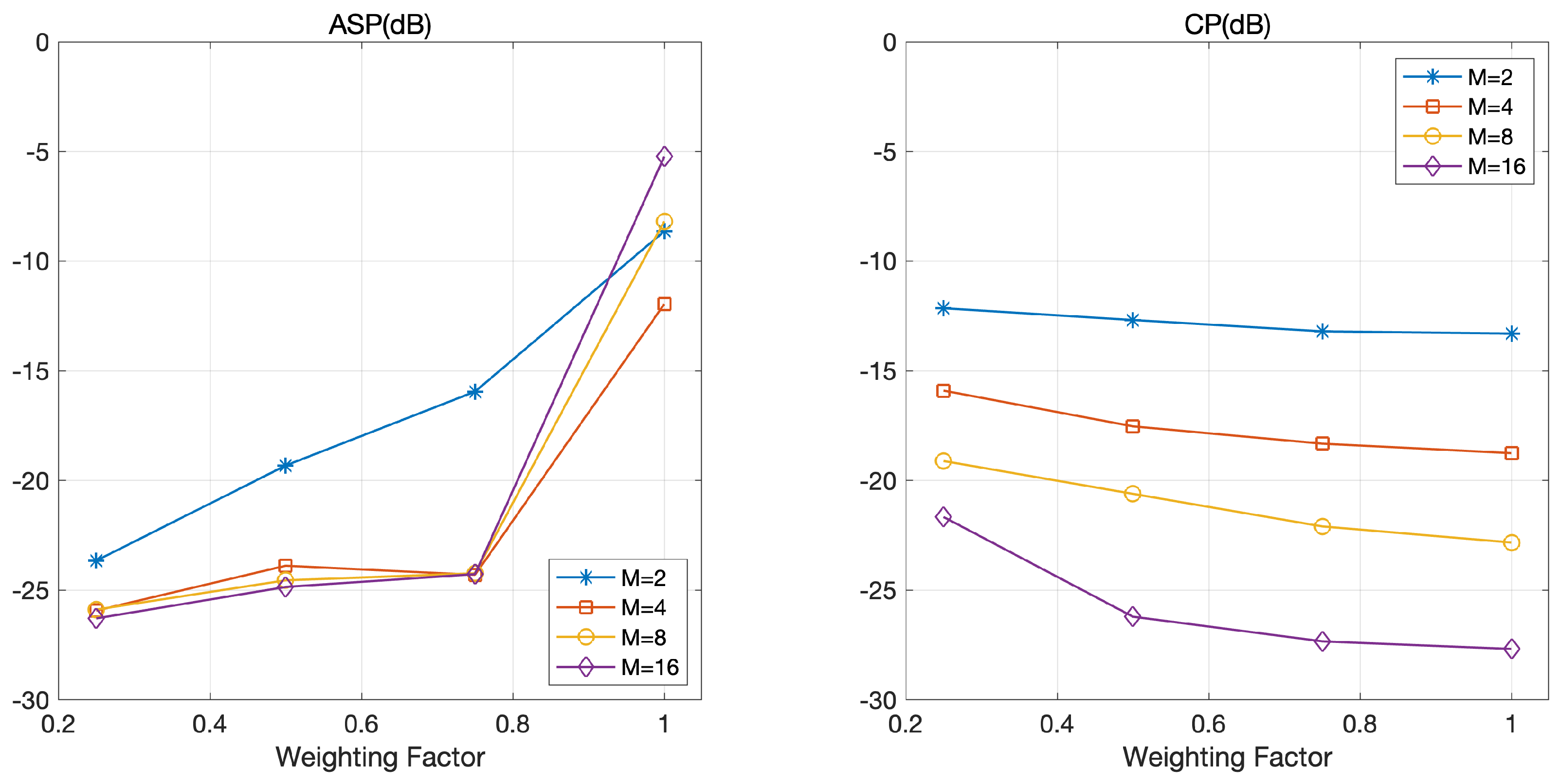
Recall that the weighting factor is an important design parameter affecting the and of optimized coded LFM waveforms. Specifically, a set of coded LFM waveforms with a large reduces aggressively while sacrificing . Thus, we evaluated the and of the optimized coded LFM waveforms of our scheme according to .
Figure 6 depicts and according to a weighting factor . As expected, decreases with and increases with . There are two interesting observations in Figure 6. First, slightly increases with in the regime with a small 0.75) and abruptly increases with in the regime of a large 0.75). However, slightly decreases with in both regimes. Specifically, the increase in in the regime of a large induces a small gain in but significantly degrades . Second, we do not find any tendency between and M when is 1. However, we observe that a large M is helpful for reducing . This is because is not considered in the optimization process when is 1.
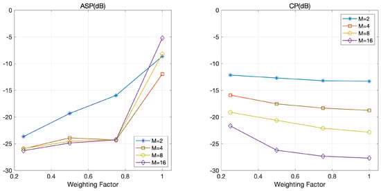
Figure 6.
and according to the weighting factor in various settings for M:, 4, 8, and 16.
5. Discussion
In Table 3, we compare the performances of our scheme with those of previous proposals [6,7,13]. More specifically, the proposed scheme outperformed the previous proposals even when our scheme employed a shorter code length and a larger number of radars than the previous proposals. We emphasize that the orthogonal waveforms from our scheme showed better orthogonality than those from previous proposals even using a narrower bandwidth and supporting more radars. In other words, the frequency efficiency of our scheme is much better than previous proposals [6,7,13].
Table 3.
Performance comparison.
It should be noted that we must consider both the computational complexity and orthogonality when generating orthogonal waveforms using the proposed scheme. Specifically, large numbers of M and N induce a large DoF in the optimization process, but the computational complexity of the optimization process increases exponentially with M and N. Moreover, the coded LFM waveform with a large M is vulnerable to noise. Therefore, the careful selection of design parameters (e.g., L, M, N) is important for generating a set of optimized coded LFM waveforms.
To exploit the proposed waveform in practice, we need to analyze the performance of the range and Doppler measurements of the optimized coded LFM waveform compared to a single (uncoded) LFM waveform. For this purpose, using MATLAB, we obtain ambiguity functions of the proposed optimized coded LFM and a single (uncoded) LFM waveform, where the ambiguity function at a non-zero delay and Doppler frequency corresponds to returns from the range and Doppler that are different to those of the nominal target [20]. The LFM waveform is constructed with a pulse width of 1 s and sweep bandwidth of 32 MHz. To generate an optimized coded LFM waveform set that has the same bandwidth as the LFM waveform, we encoded polyphase code sequences with a chip bandwidth of 16 MHz to an LFM waveform sweeping 16 MHz for 1 s.
Figure 7 shows the range–Doppler result obtained through the zero-delay cut and the zero-Doppler cut ambiguity functions. As shown in Figure 7, the ambiguity functions of the non-zero delay of the proposed waveform are relatively higher than those of a single LFM waveform. This implies that accuracy of range measurements could be reduced when there are multiple targets in close proximity (we can improve the accuracy of range detection by employing a post-processing algorithm at the receivers (e.g., the CLEAN algorithm)). Moreover, the ambiguity function of the non-zero Doppler of the proposed waveform is comparable to that of a single LFM waveform, which means that the accuracy of Doppler measurement is rarely degraded.
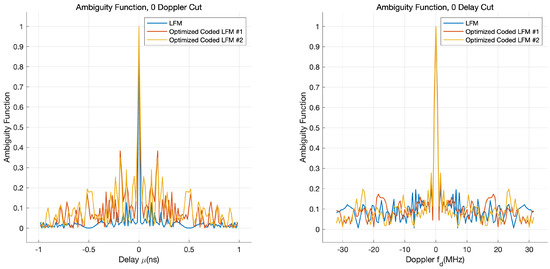
Figure 7.
Range–Doppler relationship of a single LFM and optimized coded LFM waveforms.
6. Conclusions
In this paper, we propose a scheme for designing a set of optimized coded LFM waveforms. Contrary to previous approaches that derive a set of orthogonal codes that maximize the orthogonality of the codes and then use the derived codes to encode LFM waveforms, our scheme derives an optimal set of coded LFM waveforms, maximizing the orthogonality of the waveforms. For this purpose, our scheme employed a new optimization framework in which we found a set of coded LFM waveforms that minimize an objective function. Through in-depth simulation studies, we confirmed that the proposed scheme generated a set of waveforms with better orthogonality than previous proposals in terms of autocorrelation sidelobe peaks and cross-correlation peaks.
Author Contributions
Conceptualization, D.-H.K.; Investigation, D.-H.K.; Software, D.-H.K.; Supervision, H.-J.K. and J.-H.L.; Writing—original draft, D.-H.K.; Writing—review & editing, H.-J.K. and J.-H.L. All authors have read and agreed to the published version of the manuscript.
Funding
This work was supported by Institute of Information & communications Technology Planning & Evaluation (IITP) grant funded by the Korea government (MSIT) (2020-0-00878, Development of Core Technology for Efficient Radar Spectrum Use), and by the Research Grant of Kwangwoon University in 2021.
Conflicts of Interest
The authors declare no conflict of interest.
Abbreviations
The following abbreviations are used in this manuscript:
| ASP | Autocorrelation Sidelobe Peak |
| CP | Cross-correlation Peak |
| DoF | Degree of Freedom |
| LFM | Linear Frequency Modulation |
| SSCL | Spread Spectrum Coded LFM |
| SSRS | Spectrum Shared Radar System |
References
- Deng, H. Orthogonal netted radar systems. IEEE Aerosp. Electron. Syst. Mag. 2012, 27, 28–35. [Google Scholar] [CrossRef] [Green Version]
- Geng, Z. Evolution of netted radar systems. IEEE Access 2020, 8, 124961–124977. [Google Scholar] [CrossRef]
- Lim, J.H.; Lim, D.W.; Cheong, B.L.; Song, M.S. Spectrum sharing in weather radar networked system: Design and experimentation. IEEE Sens. J. 2018, 19, 1720–1729. [Google Scholar] [CrossRef]
- Deng, H. Polyphase code design for orthogonal netted radar systems. IEEE Trans. Signal Process. 2004, 52, 3126–3135. [Google Scholar] [CrossRef]
- Majumder, U.; Bell, M.R.; Rangaswamy, M. Design and analysis of radar waveforms achieving transmit and receive orthogonality. IEEE Trans. Aerosp. Electron. Syst. 2016, 52, 1056–1066. [Google Scholar] [CrossRef]
- Ramarakula, M.; Ramana, V. Optimization of Polyphase Orthogonal sequences for MIMO Radar Using Genetic Algorithm with Hamming Scan. In Proceedings of the 2019 IEEE International Conference on Advanced Networks and Telecommunications Systems (ANTS), Goa, India, 16–19 December 2019; pp. 1–5. [Google Scholar]
- Bingnan, P.; Pei, T.; Zhang, H. Orthogonal Waveform Design of MIMO Radar Based on Niche Genetic Algorithm. In Proceedings of the 2020 IEEE International Conference on Signal Processing, Communications and Computing (ICSPCC), Macau, China, 21–24 August 2020; pp. 1–6. [Google Scholar]
- Tang, B.; Tuck, J.; Stoica, P. Polyphase Waveform Design for MIMO Radar Space Time Adaptive Processing. IEEE Trans. Signal Process. 2020, 68, 2143–2154. [Google Scholar] [CrossRef]
- Welstead, S. Characterization of diversity approaches for LFM stretch-processed waveforms. In Proceedings of the 2007 International Waveform Diversity and Design Conference, Pisa, Italy, 4–8 June 2007; pp. 418–422. [Google Scholar]
- Lulu, A.; Mobasseri, B.G. Chirp diversity waveform design and detection by stretch processing. In Proceedings of the 2016 IEEE Radar Conference (RadarConf), Philadelphia, PA, USA, 2–6 May 2016; pp. 1–6. [Google Scholar]
- Wang, W.Q. Large time-bandwidth product MIMO radar waveform design based on chirp rate diversity. IEEE Sens. J. 2014, 15, 1027–1034. [Google Scholar] [CrossRef]
- Qazi, F.A.; Fam, A.T. Good code sets based on Piecewise Linear FM. In Proceedings of the 2012 IEEE Radar Conference, Atlanta, GA, USA, 7–11 May 2012; pp. 0522–0527. [Google Scholar]
- Qazi, F.A.; Fam, A.T. Doppler tolerant and detection capable polyphase code sets. IEEE Trans. Aerosp. Electron. Syst. 2015, 51, 1123–1135. [Google Scholar] [CrossRef]
- Li, H.; Zhao, Y.; Cheng, Z.; Feng, D. OFDM chirp waveform diversity design with correlation interference suppression for MIMO radar. IEEE Geosci. Remote Sens. Lett. 2017, 14, 1032–1036. [Google Scholar] [CrossRef]
- Wanbing, G.; Zeng, X. Optimal Waveform Design Using Frequency-Modulated Pulse Trains for Active Sonar. Sensors 2019, 19, 4262. [Google Scholar] [CrossRef] [Green Version]
- Chang, G.; Liu, A.; Yu, C.; Ji, Y.; Wang, Y.; Zhang, J. Orthogonal Waveform with Multiple Diversities for MIMO Radar. IEEE Sens. J. 2018, 18, 4462–4476. [Google Scholar] [CrossRef]
- Wei, Y.; Mao, Z. Novel Range-Doppler Processing and Waveform Design Method for Extending Unambiguous Doppler. In Proceedings of the 2018 International Conference on Radar (RADAR), Brisbane, Australia, 27–30 August 2018; pp. 1–5. [Google Scholar] [CrossRef]
- MATLAB. Version 9.9.0.1592791 (R2020b); The MathWorks Inc.: Natick, MA, USA, 2020. [Google Scholar]
- Kim, B.K.; Park, J.; Park, S.J.; Kim, T.W.; Jung, D.H.; Kim, D.H.; Kim, T.; Park, S.O. Drone Detection with Chirp-Pulse Radar Based on Target Fluctuation Models. ETRI J. 2018, 40, 188–196. [Google Scholar] [CrossRef]
- Mahafza, B.R. Radar Systems and Design Using MATLAB, 3rd ed.; CRC Press: Boca Raton, FL, USA, 2013. [Google Scholar]

Publisher’s Note: MDPI stays neutral with regard to jurisdictional claims in published maps and institutional affiliations. |
© 2021 by the authors. Licensee MDPI, Basel, Switzerland. This article is an open access article distributed under the terms and conditions of the Creative Commons Attribution (CC BY) license (https://creativecommons.org/licenses/by/4.0/).