1. Introduction
With the increase in the demand for the Internet of Things, cyber-physical systems, and smart buildings, there continues to be a high interest in vibration energy harvesting to create self-sustaining systems through the harvesting and conversion of mechanical energy from the ambient environment into usable electrical energy. Most vibration energy harvesters consist of a cantilever beam as a mechanical system that oscillates due to an applied vibration from the environment. The different kinetic energy converting mechanisms include piezoelectrics, electromagnetics, electrostatics, or triboelectrics. The energy converting mechanisms are different for each of these, but all these methods rely on a similar mechanical oscillating system. Typically, these cantilevers are linear systems with high Q-factors or narrow bandwidths of <2 Hz (~1% of resonant frequency) operating at low frequencies of <250 Hz [
1,
2,
3,
4,
5,
6]. The narrow bandwidths allow them to have high power density, but it limits their use in real-life applications, as even a 1% change in resonant frequency will significantly reduce the amount of power harvested. Large changes in resonant frequency can occur due to small changes in the vibration source or even due to manufacturing non-uniformities of the cantilever. Therefore, wider bandwidth devices are necessary for practical applications.
Since bandwidth is one of the major challenges associated with vibration energy harvesting, it was extensively investigated. Previous attempts to solve this issue have included developing non-linear cantilevers and spring designs based on duffing resonators [
7,
8,
9,
10], impact driven mechanical stoppers [
11,
12,
13], additional magnetic forces [
14,
15,
16], bistable non-linear devices [
17,
18,
19], and the designing of an array of devices with varying frequencies [
4]. However, these methods have numerous disadvantages, such as hysteresis effects, which depend on frequency sweep testing protocol, low power density, as decreasing the Q-factor reduces the peak power harvested, a larger footprint, thus decreasing the overall power density, complex manufacturing, especially at the micro-scale, and the need for external power, which reduces the overall efficiency of the system. Impact-based systems causing non-linear dynamics were also recently investigated and have demonstrated an increase in bandwidth [
20,
21], but the methods investigated to date consist of impact methods that are not scalable down to the micro-scale needed for IoT applications.
Recently, there were numerous attempts to increase the bandwidth by using a lateral sliding mass, which changes the center of gravity of the proof mass during oscillation, resulting in a continuously changing resonant frequency in a process referred to as dynamic tuning [
22]. This dynamic tuning has the effect of widening the bandwidth. Previous attempts to create a sliding mass include using rolling cylinders [
23,
24,
25,
26], sloshing liquids [
22,
27,
28,
29,
30], and a combination of the two [
31]. These wide bandwidth methods involve altering the resonant frequency during oscillation by changing the effective location of the proof mass. The various methods demonstrated limited success as they rely on a large change in the center of gravity to significantly increase the bandwidth. The large lateral displacements required to widen the bandwidth are potentially feasible in macro-scale devices, but scaling down to the micro-scale would limit lateral displacement of the movable mass. In addition, these devices increase the bandwidth when compared to a traditional linear (stationary proof mass) system, but altering the center of gravity has only a minor effect on the overall effective mass, which limits the bandwidth enhancement capabilities.
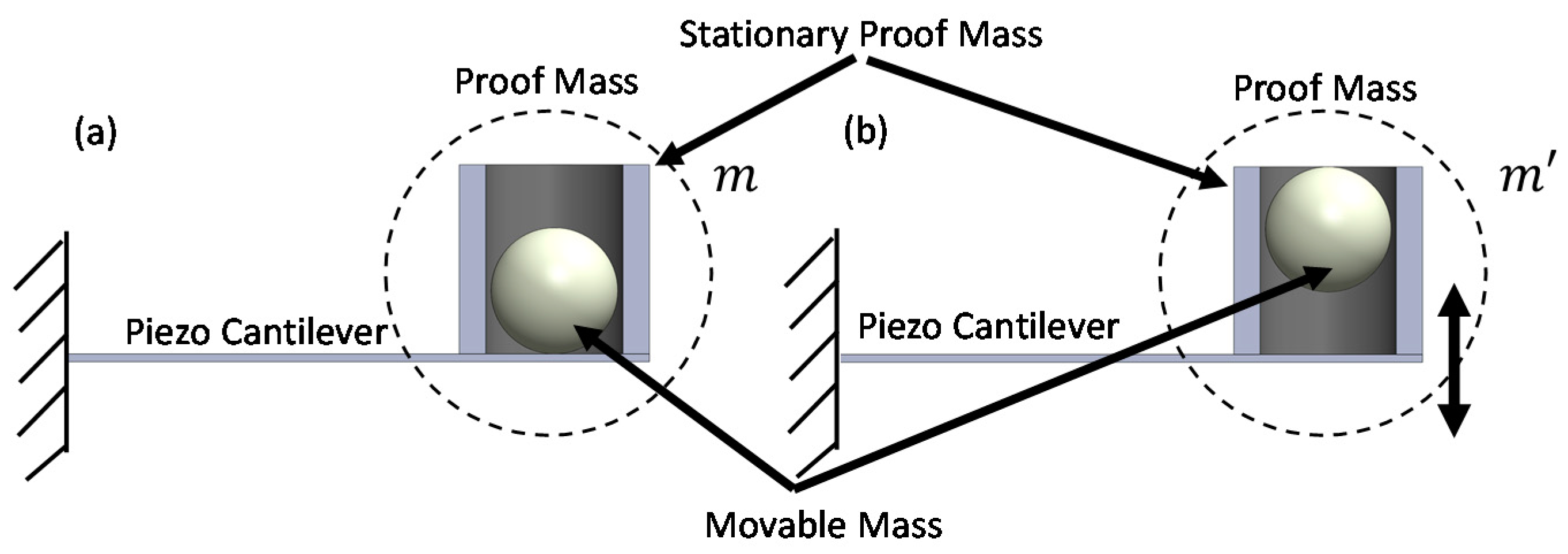
This paper investigated the experimental validation of a novel movable mass energy harvesting system aimed at widening the bandwidth. Instead of a lateral moving mass, this paper investigated a vertical or transverse movable mass component. The transverse movable mass concept combined: (i) a continuous alteration of the effective proof mass to change the resonant frequency during operation, and (ii) the non-linear dynamics based on the impact of the movable mass on the cantilever substrate, in order to increase the bandwidth without a significant decrease in power. This is the first time a vertical movable mass was embedded into the proof mass of an energy harvesting system. The development of a transverse movable mass has the potential to significantly alter the effective mass of the system, resulting in the continuous altering of the resonant frequency during operation. The transverse movable mass is potentially a preferred option over a lateral sliding mass because it provides a larger change in the overall mass of the system, which correlates to an increase in bandwidth. This method also has the potential to be applied to both macro- and micro-scale devices, as embedded powders in silicon cantilevers were previously developed [
32], which could act as a movable mass for MEMS cantilevers. This paper uses a piezoelectric cantilever as the energy harvesting system, but the method of widening the bandwidth can be applied to any cantilever device. This paper investigated the power and bandwidth effects of a transverse movable mass cantilever-system by performing experimental testing associated with varying the acceleration, the amount of movable mass, the size of the movable mass, and varying the material density of the movable mass. The movable mass method under investigation was expected to be utilized for applications requiring large acceleration and low frequency, such as aerospace, automotive, or pacemaker applications [
33,
34]
3. Results and Discussion
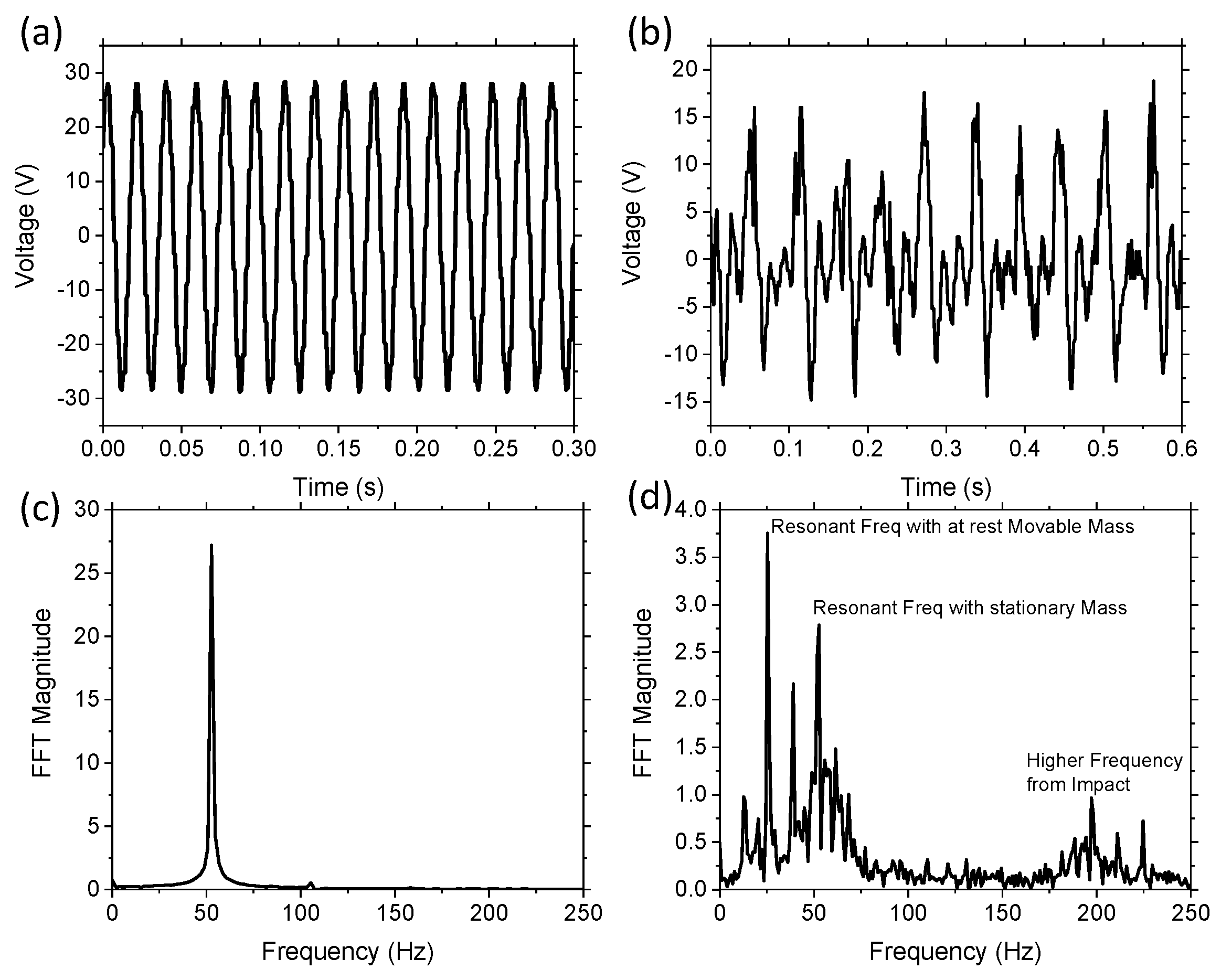
The initial validation of the concept was investigated experimentally by comparing the output voltage as a function of time for two devices operating at 1 g acceleration. The first device was the control, which consisted of the cantilever beam and a stationary 3D printed proof mass without any movable balls in the chambers. The second device consisted of a cantilever beam, stationary proof mass, and one W ball in the middle chamber. In both cases, the vibration source was applied at the resonant frequency of the cantilever with proof mass. The control proof-mass was lighter, having a resonant frequency of ~53 Hz, whereas, when we added the extra mass of the movable ball, the resonant frequency was ~25 Hz.
Figure 3a is a section of the raw data from the oscilloscope while operating near the resonant frequency of the control device with no movable component. The movable mass was restricted from moving in the lateral direction due to the size of the chamber, and thus allowed the ball to only move in the vertical transverse direction. The results of the control system with no movable mass demonstrated a typical linear device with a sinusoidal output. The FFT of these results demonstrated a single resonant frequency at 53 Hz, as shown in
Figure 3c. The experimental raw data for the device with movable mass is shown in
Figure 3b. The results demonstrate that the movable mass generated an output voltage consisting of multiple frequencies, with a peak resonant frequency of approximately 25 Hz. The reduction in resonant frequency was due to the increased overall proof mass. The large voltage peaks consisted of linear frequencies when the movable mass was in contact with the cantilever and when the system was in free fall. Visual confirmation of the ball moving was seen through the chamber and the ball displacement was approximately 1 cm in height. The FFT of the movable mass device is demonstrated in
Figure 3d, which shows multiple frequencies, including a peak at 53 Hz. The 53 Hz peak is demonstrated in both
Figure 3c,d, as this represents the resonant frequency of the cantilever with the stationary 3D printed mass.
Figure 3d also has a large peak at 25 Hz, which is the resonant frequency of the cantilever with the additional W mass while at rest on the surface. Numerical analysis using Equation (1) estimates the resonant frequency of the two masses to be 26 Hz and the free fall state resonant frequency to be 52 Hz, which is in good agreement with the experimental results. The difference was likely to be a result of a slight difference in the elastic modulus of the cantilever. The FFT data demonstrated multiple frequencies in the 10–75 Hz range, even though the excitation frequency was at 25 Hz, which was due to the non-linear impact of balls and the changing resonant frequency of the cantilever. There were also higher frequency peaks at around 175–225 Hz, which was due to the impact of the ball hitting the chamber. The results validate that there was a wider range of frequencies occurring in the system with the movable mass. The addition of these multiple frequencies should have the effect of increasing the bandwidth, as significant voltage output can be measured through a wide range of frequencies compared to the linear control system in
Figure 3c, which only has a single frequency output.
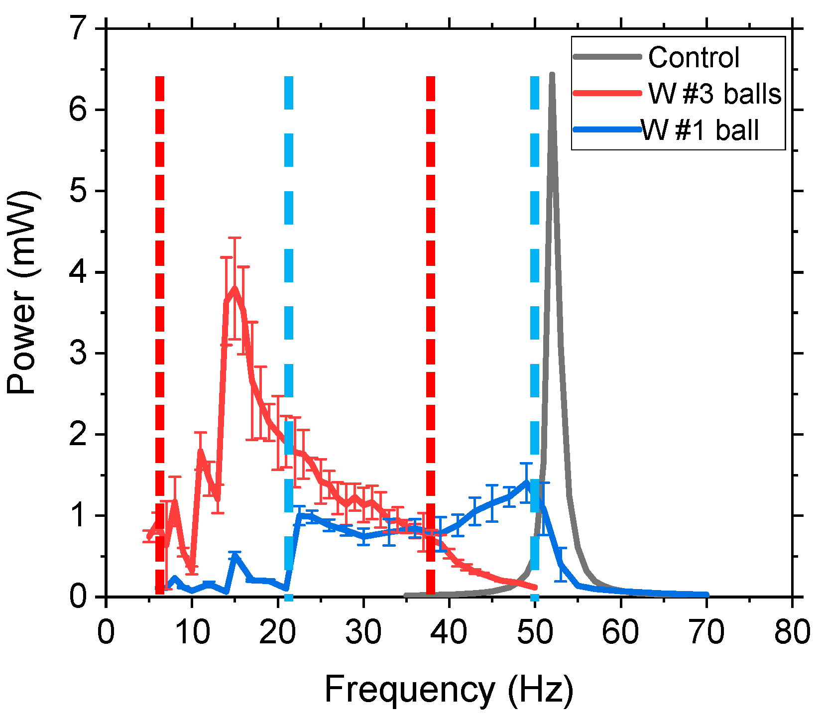
Next, we varied the number of balls in each chamber to determine if the wt.% of movable mass had a significant impact on bandwidth. The power, as a function of applied frequency, was measured for the (i) control (no movable mass), (ii) one middle 10 mm diameter W ball, and (iii) three W balls (one in each chamber), which were experimentally investigated at 1 g acceleration. The power was measured by connecting the output voltage of the cantilever to a variable load resistor to match the impedance for maximum power. The results are demonstrated in
Figure 4. The control system had a typical linear dynamic response, with a sharp peak and full width half maximum (FWHM) of 1.5 Hz, and a peak power of 6.43 mW at 53 Hz. The movable mass device (a single W ball), with a 44% movable mass, had a wider bandwidth with a peak frequency shifted to the left (lower frequency) due to the additional mass in the system. The average power was calculated for each frequency over a 1 min duration, and the standard deviation was represented by error bars. The single ball system had a much wider bandwidth compared to the control, which had no movable mass component, and a FWHM (~30.5 Hz compared to 1.5 Hz) and no distinguishable peak, but the average power measured was 1.4 mW. The results of adding a single ball with a 44 wt.% movable mass significantly increased the bandwidth, but decreased the power. The three-ball system, with a 70.2 wt.% movable mass, demonstrated a high bandwidth and a high peak power of 3.8 mW at 15 Hz. The area under the curve, which represents the power over a range of frequencies (mW-Hz), was increased by 117% and 252% for the one-ball and three-ball system, respectively, compared to the control. The three-ball system had a NLBW range of 34 Hz, which demonstrated average power values of >0.7 mW during that frequency range, with the exception of one point around 10 Hz. This validated the concept that a vertical movable mass can widen the bandwidth and increase power generation. The peak power of the movable mass system was reduced compared to the control, but the bandwidth was significantly increased. Increasing the percent of the movable mass further increased the peak power, while still maintaining a high bandwidth as the power over a frequency range was significantly increased. Balls placed on the outside chambers caused high frequency twisting modes to decrease their resonant frequency as well, but the research was interested in low frequency first mode operation to increase the power density.
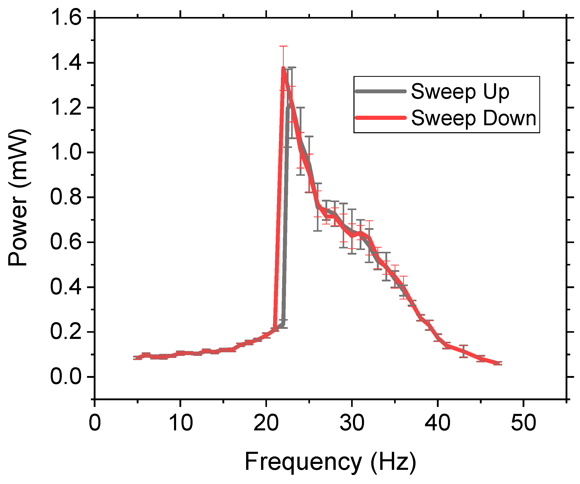
The non-linear energy harvester’s bandwidth and power measurements are commonly dependent on the frequency sweep characteristics of the applied excitation where there is a hysteresis effect; thus the operation of the device is dependent on the testing parameters of sweeping the frequency either up or down [
39,
40,
41]. However, this is not practical as most applications have randomly changing discreet frequencies instead of a continuous sweep. To investigate if the frequency sweep direction had an impact on the power or bandwidth, the frequency was swept in both directions at a rate of 0.05 Hz/s from 5–50 Hz at 0.5 g with a three-ball system of W. The results (
Figure 5) demonstrated no significant difference in amplitude or bandwidth due to sweeping the frequency. The results were further validated by randomly selecting frequencies and measuring their output power, which demonstrated that, within the standard deviation, the results were the same. Therefore, this method has potential impact in real-life applications as the power and bandwidth can be accurately predicted regardless of testing parameters. Comparing the results of the three-ball system in
Figure 4 (1 g) and
Figure 5 (0.5 g) the general shape of the output power vs. frequency was the same, but the 1 g acceleration had higher power, as expected, and higher bandwidth due to the increased impact force. Increasing the acceleration to 1 g and 1.5 g obtained similar results, demonstrating no significant hysteresis effect.
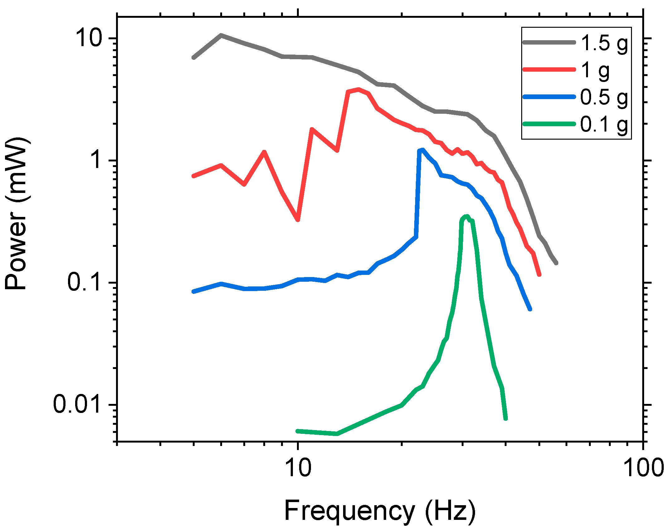
The power and bandwidth are dependent on the acceleration that is applied, and it was believed that the vertical movable mass method required high acceleration because low acceleration would not have a large enough tip displacement to propel the mass within the chamber, thereby limiting the non-linear dynamic effects. To investigate this, various accelerations from 0.1, 0.5, 1, and 1.5 g were experimentally tested with the three-ball system using W balls. The results are presented in
Figure 6. At 0.1 g, the system behaved like a linear system with a slight increase in the FWHM of 1.73 Hz as compared to the control’s 1.2 Hz. As the acceleration increased, there was a shift in the peak power amplitude towards a lower frequency. This occurred because the higher acceleration resulted in higher force, which increased the tip displacement and caused the movable mass to propel off the surface at lower frequencies. This, in turn, increased the NLBW as the frequency range of the movable mass was increased, thus generating a larger non-linear region due to the impact force. Once the mass started moving, the peak power increased along with the bandwidth. At 1.5 g, the peak power occurred at 6 Hz because the high acceleration and low frequency produced a large enough force to propel the movable mass off of the substrate. This resulted in a peak power of 10.52 mW. Higher acceleration also caused the bandwidth to increase as the area under the curve increased from 1.73, 13.99, 53.91, and 147.23 mW-Hz for 0.1, 0.5, 1, and 1.5 g, respectively. The area under curve represents the total amount of power that is harvested over a range of frequencies. The experimental results demonstrated that this method is efficient for low frequency, high acceleration applications.
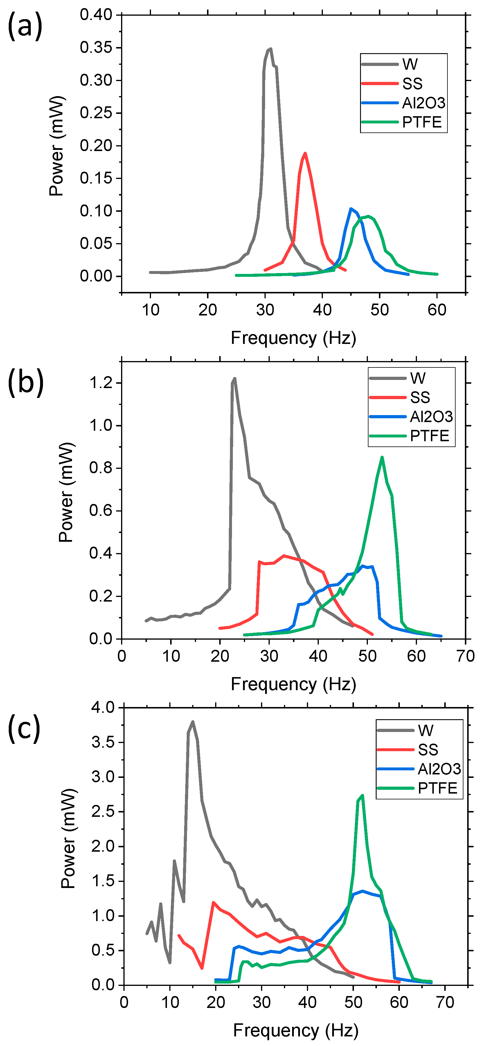
Various density balls, as highlighted in
Table 1, were used to determine the effects varying the wt.% of movable mass had on the bandwidth and power. Three 10 mm diameter balls, one in each chamber, were used in the experiment with varying accelerations from 0.1, 0.5, and 1 g. The results are shown in
Figure 7. At a low acceleration of 0.1 g (
Figure 7a), all of the materials used for the balls (W, SS, Al
2O
3, and PTFE) had an output that more closely represented a linear system. As the density of the balls increased, there was a peak power shift towards lower frequencies, which was expected since the overall weight of the proof mass increased. The peak power was dependent on the density of the balls and the overall mass of the system, as expected, demonstrating an increase in the power with an increase in the percentage of movable mass. However, the FWHM value decreased as the amount of movable mass increased, with values of 2.61, 3.01, 3.7, and 5.2 Hz for W, SS, Al
2O
3, and PTFE, respectively, compared to the control’s FWHM of 1.2 Hz. The PTFE balls had a wider bandwidth at a low acceleration because they required less force to propel as compared to the denser masses, such as W, which required more force. Therefore, low-density movable masses provided wider bandwidths than dense materials at low acceleration because the higher density balls did not easily propel off the substrate, resulting in limited impact force.
As the acceleration increased, the cantilevers with denser masses demonstrated an increase in bandwidth and all of the systems had a larger NLBW, as shown in
Figure 7b,c, because the acceleration produced a large enough force to propel the movable mass. For example, at 0.5 g, the W balls had a high intensity peak (1.22 mW) at a low frequency and a FWHM of 9.29 Hz. However, it started to develop a broader peak at higher frequencies, thus increasing the bandwidth of usable energy. Usable energy, as defined by the authors, is power >0.7 mW, which was determined based on the typical power requirements for wireless sensor networks, wherein 0.7 mW is adequate for most IoT applications. However, at 0.5 g, the SS balls lacked a high-intensity, narrow peak, instead consisting of a broad peak with an average power of 0.38 mW and a bandwidth of 15.4 Hz. The Al
2O
3, on the other hand, had a broad peak at lower frequencies and started to develop a high-intensity peak at the resonant frequency of the stationary system. This resulted in an average power of 0.25 mW and a bandwidth of 14.52 Hz. The PTFE movable mass system had a high-intensity peak at the resonant frequency of the stationary proof mass, with a peak power of 0.85 mW and a FWHM of 6.81 Hz, but it also consisted of a wider peak at lower frequencies due to the non-linear movable masses. The reason for the high peak exhibited by PTFE was attributed to two issues: (1) the low density of the balls caused a lower impact as compared to W, so the non-linear effects were less, and (2) the less-dense balls had a larger displacement within the chamber, thus the time required for the balls to impact the substrate was longer, resulting in a larger linear dynamic region for a longer amount of time. For example, if the PTFE balls had a 1.5 cm vertical displacement within the chamber the free fall, the time it would take for the balls to fall would be ~55 ms, whereas the time for the cantilever to complete one cycle is ~19 ms, thus the cantilever would be in linear mode for nearly three oscillation cycles before the impact. The W ball system had a large narrow peak at low acceleration due to the cantilever’s limited amount of force and displacement, which resulted in the low displacement of the balls and a low impact force. As acceleration increased, the balls had a larger displacement, resulting in a larger NLBW region. The denser balls had a larger impact force when they were propelled. Therefore, the low-density movable masses resulted in a more linear system, but at high acceleration, the system had both linear and nonlinear components.
The power, as a function of the frequency results, of applying a 1 g acceleration (
Figure 7c) demonstrated a similar trend as the results in
Figure 7b. The Al
2O
3 ball appeared to be shifting in the same manner as the PTFE samples to form a peak at the linear resonant frequency. At 1 g, however, a significant narrow peak was still absent, but increasing the acceleration is likely to cause a rise in the peak at the stationary resonant frequency. Both PTFE and Al
2O
3 had two distinguished modes: (i) a wide plateau mode at lower frequencies of 20–45 Hz approximately (non-linear region), and (ii) a higher intensity peak region (linear). This resulted in the two systems having both a narrow high-power density section (the linear component) and a lower power density wider bandwidth section (the non-linear component). The total power over the usable frequency range resulted in an area under curve value of 28.07 and 28.8 mW-Hz for Al
2O
3 and PTFE, respectively. SS and W also increased the bandwidth and power, with the SS balls having an average power of 0.7 MW and a FWHM of 29.9 Hz. The W balls had a large peak power of 3.79 mW and a wider NLBW region, with an overall area under the curve of 54.07 mW-Hz. Therefore, we determined that a higher wt.% movable mass provided a wider bandwidth and higher power at increased acceleration. Applying a higher acceleration to the W ball system would likely cause the output to shift, similar to the outputs of PTFE and Al
2O
3, but we maintained the acceleration limit at 1 g as most practical applications operate at <1 g acceleration.
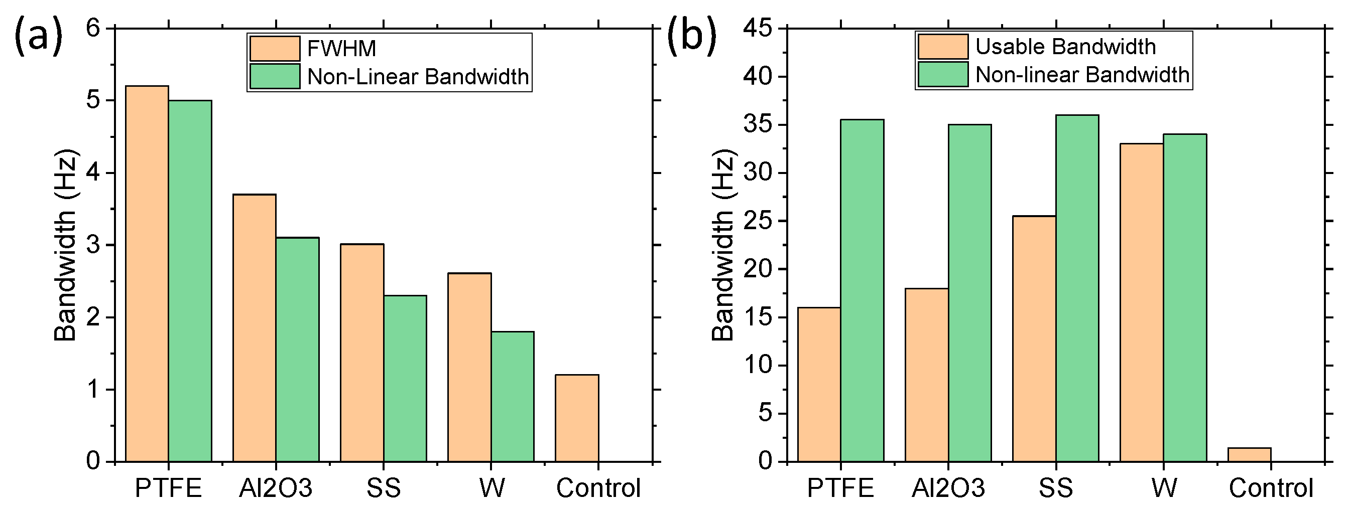
Figure 8 demonstrates the bandwidth effects of the varying materials from 0.1 g to 1 g. The results of the 0.1 g bandwidth investigation (
Figure 8a) were measured by the FWHM (as these devices behaved more like a linear system) and the NLBW, as the devices still had some movable mass components. For low acceleration, the FWHM values were similar to the NLBW range, with the NLBW being slightly reduced in all cases. However, the difference between the FWHM and NLBW increased as the density of the balls increased, which made sense since the denser balls had a larger impact force on the cantilever. In all cases, the bandwidths were significantly larger than the control with no movable mass, thus validating the concept. The bandwidth also increased as the density of the balls or total movable mass decreased because the lower density balls had larger displacements at the lower acceleration force, whereas the low acceleration force was unable to propel the higher density balls from the surface. However, as the acceleration was increased to 1 g (
Figure 8b), the NLBW approached a steady state, with all materials having similar bandwidth of 34–36 Hz. The FWHM values did not apply to the non-linear systems as they have large peaks and wide band regions, thus the term usable bandwidth was employed to represent bandwidths with a power of >0.7 mW. The usable bandwidth increased as the amount of movable mass increased. As the 1.5 g W balls demonstrated an NLBW of 43 Hz, therefore demonstrating that the saturated NLBW was dependent on the acceleration applied, it was determined that the NLBW could be further increased by increasing the acceleration.
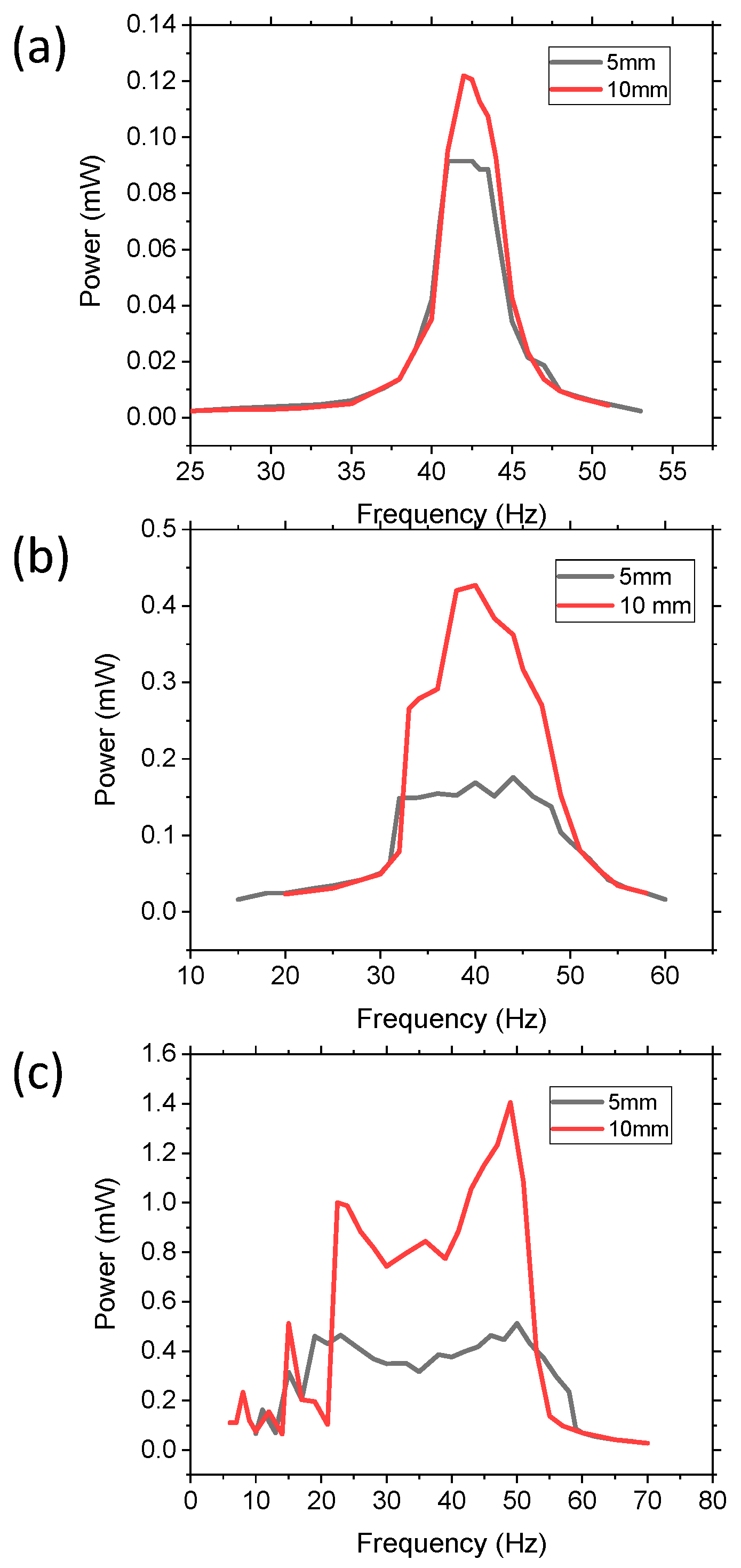
The effect of the physical dimensions of the movable masses on power and bandwidth were investigated by comparing devices with (i) one 10 mm diameter W sphere with mass of 7.87 g and (ii) eight 5 mm W spheres with mass of 7.84 g. The density of the balls was the same and only the diameter changed (5 mm vs. 10 mm). By increasing the number of 5 mm diameter balls, the two devices had approximately the same wt.% of movable mass, differing only by 0.1%. The effects with varying acceleration from 0.1, 0.5, and 1 g are demonstrated in
Figure 9. In all three accelerations, the larger diameter movable mass had higher power harvesting capabilities, but the bandwidth of the two devices was the same for an applied acceleration. For 0.1 g, the devices acted like a linear system with peaks of 0.122 and 0.09 mW and a FWHM of 3.56 and 3.85 Hz, compared to the control’s 1.2 Hz FWHM. At 0.5 g, the devices had more non-linear dynamic properties and had peak power values of 0.43 mW and 0.17 mW, with a bandwidth of 16.24 and 17.3 Hz for the 10 mm and 5 mm balls, respectively. At 1 g, the peak power increased to 1.40 mW and 0.51 mW and the bandwidth increased to 38.1 Hz and 41.2 Hz. For each acceleration, there was a slight increase in bandwidth for the smaller balls, but it was not statistically different. However, the power difference between the various accelerations was significant. Therefore, the size of the movable mass did significantly impact the amount of power harvested, but it did not significantly affect the bandwidth. The bandwidth was, thus, dependent on the percent of movable mass as well as the applied acceleration.
4. Conclusions
In conclusion, we successfully validated a novel concept of widening the bandwidth of a cantilever device by creating an embedded vertical or transverse movable mass system. The results demonstrated that the bandwidth and power effects were dependent on the acceleration and the amount, size, and density of the movable mass. The size of the movable mass directly affected the amount of power that could be harvested, but it did not have a significant effect on bandwidth. However, the density of the movable mass, which affected the overall wt.%, significantly affected both the power and bandwidth, with lower density masses preferred for low acceleration applications.
In the end, all of the abovementioned parameters influenced the bandwidth and amount of power, and further investigation is required to optimize the parameters for a specific application. By modifying these parameters, the end user may fine tune the bandwidth and power specifications to match the specifications of the application. The concept of a vertical movable mass system demonstrated a significant increase in bandwidth for high acceleration, low frequency applications. However, the concept can be implemented in low acceleration applications by using less dense movable masses. The power magnitude was dependent on the size, density, and overall percentage of the movable mass component. The dynamics of the system consisted of both linear and non-linear components, which requires further investigation in the future to enhance device performance. The vertical movable mass method described in this paper has potential use in both macro- and micro-scale cantilevers, but the concept requires further investigation at the micro-scale level to demonstrate validity.
This novel method provides researchers with an alternative means of widening the bandwidth without significantly decreasing power, and it has potential to be scaled down to the micro-scale to power IoT applications. The concept was experimentally validated using a piezoelectric energy harvesting cantilever, but the concept could also be applied to other energy harvesting systems, such as electromagnetics and electrostatics as well as other cantilever applications that require a wide bandwidth. This method is unique as it provides increased bandwidth, while also providing high peak power, demonstrating it can potentially provide both high power and high bandwidth. However, the results are dependent on various parameters and would need to be optimized to the specific application.


