
Sensor-Enabled Multi-Robot System for Automated Welding and In-Process Ultrasonic NDE

 ,
,  , ,
, ,
Abstract
:1. Introduction
2. Experimental System
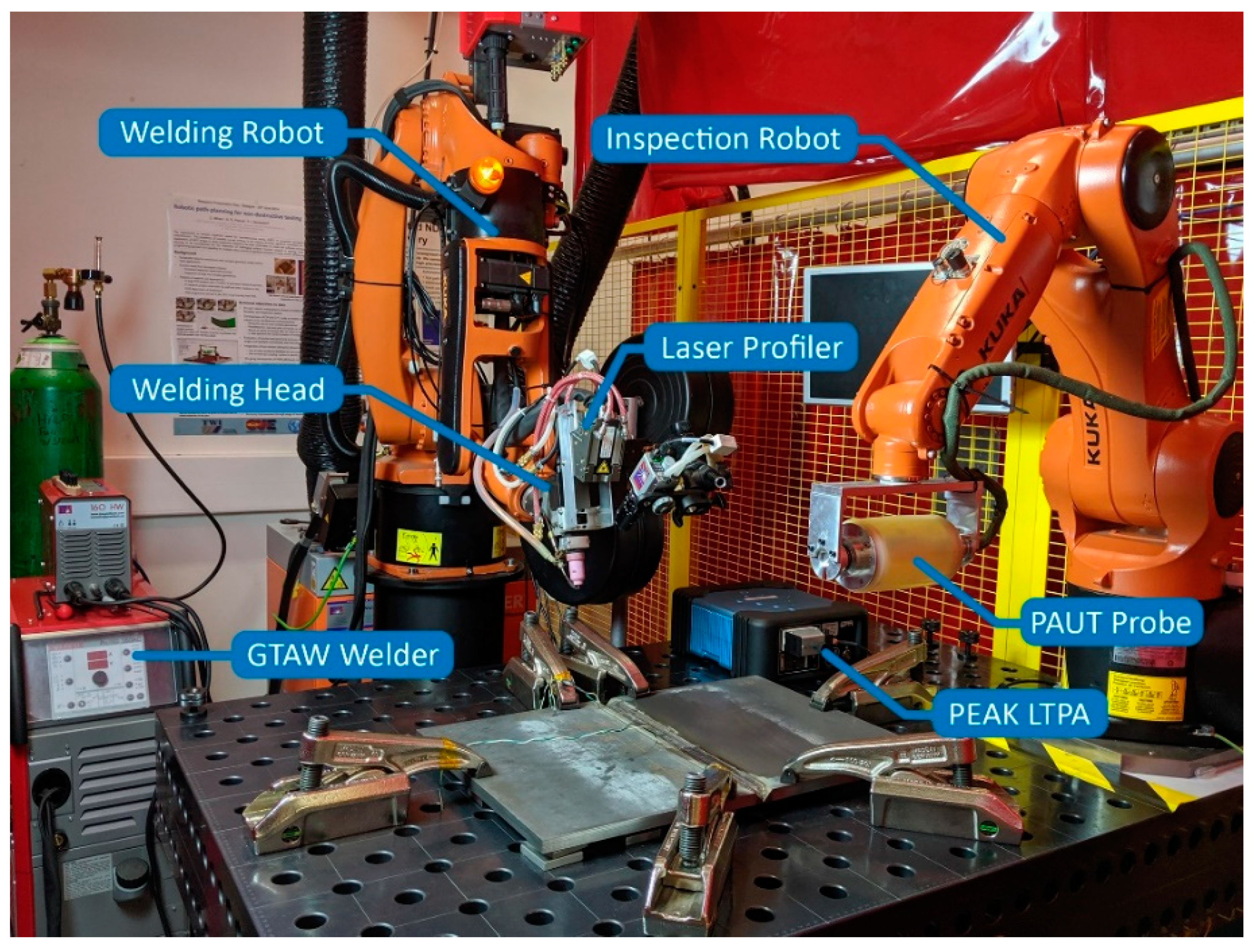
2.1. Hardware
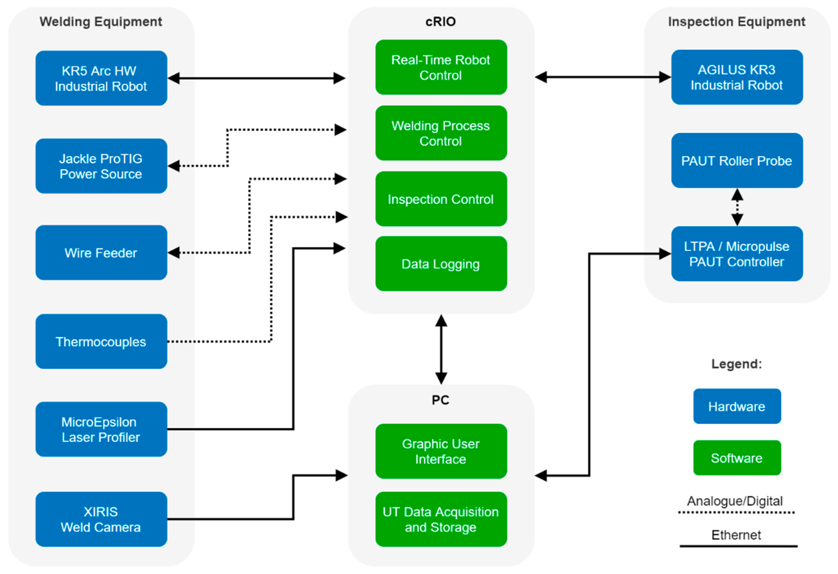
2.2. Software
2.2.1. Real-Time Robotic Control
2.2.2. Trajectory Planning
2.2.3. Welding Sequence
3. Ultrasonic Inspection
3.1. Post-Process UT
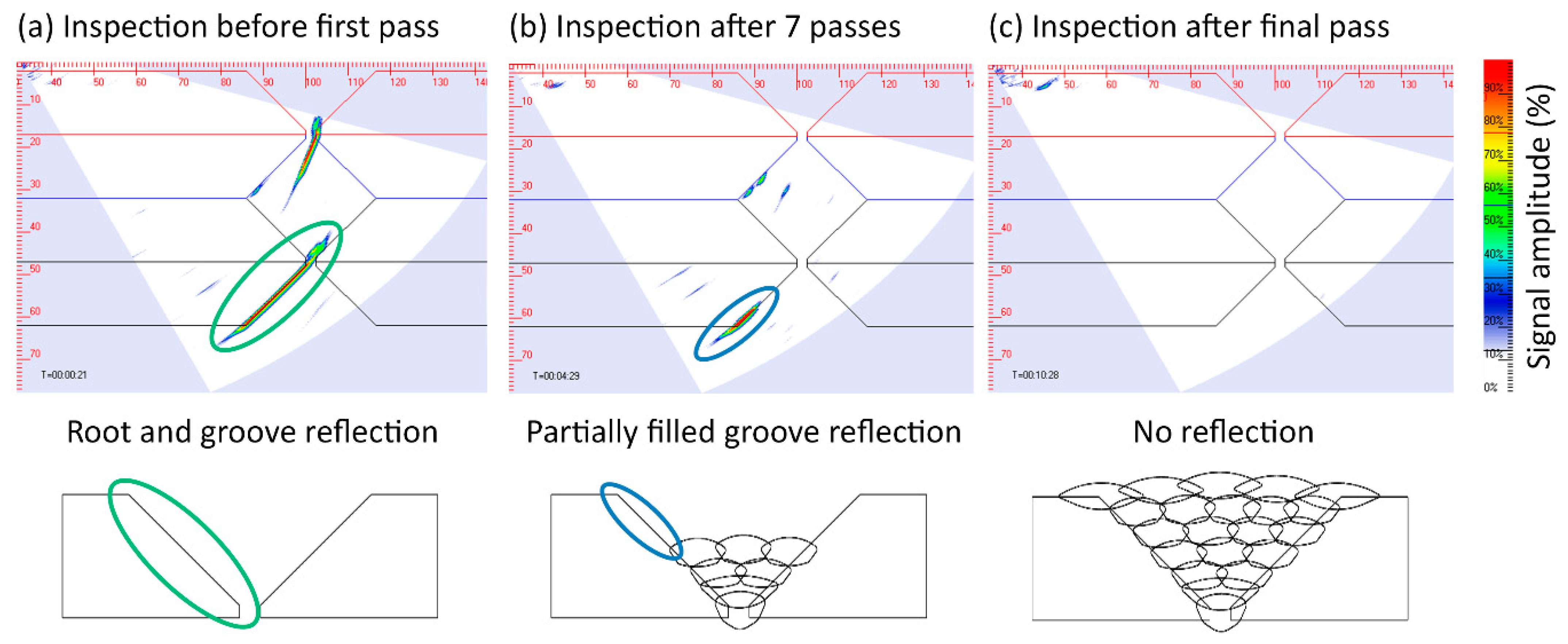
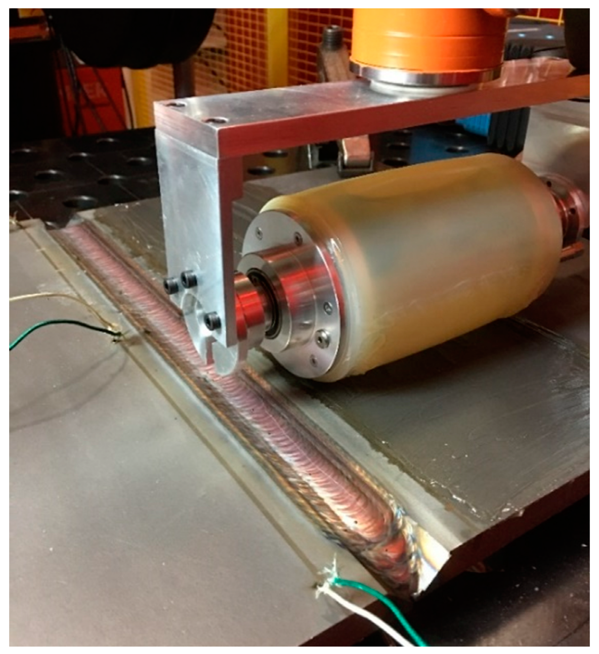
3.2. Interpass In-Process UT
3.3. Live-Arc In-Process UT
4. Conclusions and Future Work
- 1.
- Post-process continuous UT—the initiation and growth of cold crack defects was observed and measured through a continuous inspection at regular intervals after the multipass weld was completely filled.
- 2.
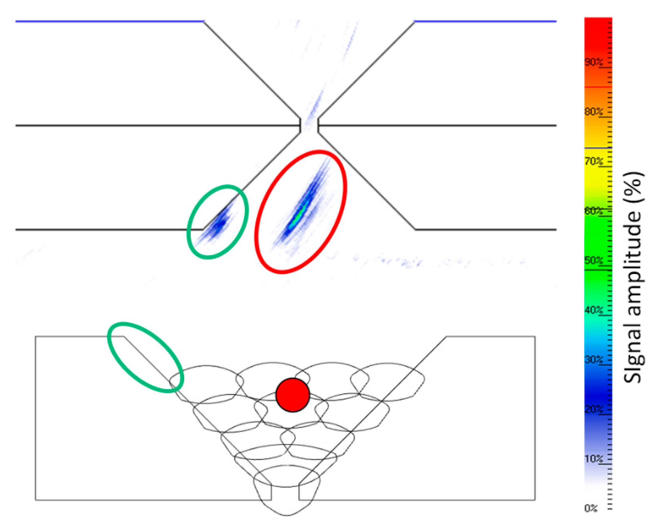
- Interpass in-process UT—the challenges due to the complex sample geometry of the unfilled weld groove were demonstrated and the inspection results showed the defect detection capabilities through artificially induced defects.
- 3.
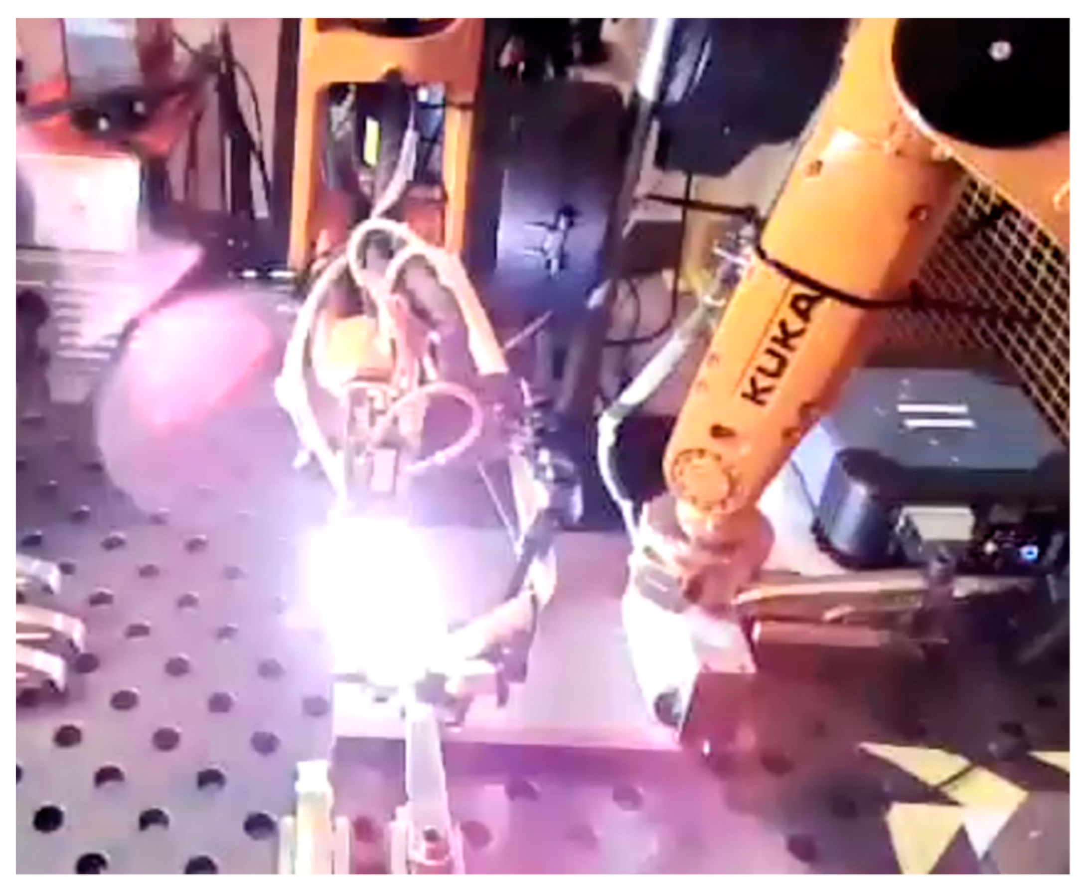
- Live-arc in-process UT—the deployment and application of three different ultrasonic sensors during live-arc welding deposition was outlined and the challenges and results were discussed.
Author Contributions
Funding
Institutional Review Board Statement
Informed Consent Statement
Data Availability Statement
Conflicts of Interest
References
- Chinchane, A.; Onkar, S. Robotic Welding Market Size, Share|Welding Robot Statistics by 2026. Available online: https://www.alliedmarketresearch.com/robotic-welding-market (accessed on 17 March 2021).
- What is Industry 4.0? How Does it Work? (A Beginners Guide). Available online: https://www.twi-global.com/what-we-do/research-and-technology/technologies/industry-4-0.aspx (accessed on 8 April 2021).
- Mineo, C.; MacLeod, C.; Morozov, M.; Pierce, S.G.; Lardner, T.; Summan, R.; Powell, J.; McCubbin, P.; McCubbin, C.; Munro, G.; et al. Fast ultrasonic phased array inspection of complex geometries delivered through robotic manipulators and high speed data acquisition instrumentation. In Proceedings of the 2016 IEEE International Ultrasonics Symposium (IUS), Tours, France, 18–21 September 2016; pp. 1–4. [Google Scholar]
- Dobie, G.; Summan, R.; Pierce, S.G.; Galbraith, W.; Hayward, G. A Noncontact Ultrasonic Platform for Structural Inspection. IEEE Sens. J. 2011, 11, 2458–2468. [Google Scholar] [CrossRef] [Green Version]
- Hashem, J.A.; Pryor, M.; Landsberger, S.; Hunter, J.; Janecky, D.R. Automating High-Precision X-ray and Neutron Imaging Applications With Robotics. IEEE Trans. Autom. Sci. Eng. 2018, 15, 663–674. [Google Scholar] [CrossRef]
- Stern, R.M.; Berlin, A.; Fletcher, A.; Hemminki, K.; Jarvisalo, J.; Peto, J. International conference on health hazards and biological effects of welding fumes and gases. Int. Arch. Occup. Environ. Heath 1986, 57, 237–246. [Google Scholar] [CrossRef]
- OLYMPUS WeldROVER Scanner. Available online: https://www.olympus-ims.com/en/scanners/weldrover/ (accessed on 13 May 2021).
- JIREH Industries NAVIC—Weld Scanner. Available online: //www.jireh.com/products/navic-weld-scanner/ (accessed on 17 May 2021).
- Eddify Scorpion 2 Ultrasonic Tank Shell Inspection|UT Thickness Readings. Available online: https://www.eddyfi.com/en/product/scorpion-2 (accessed on 17 May 2021).
- McGregor, A.; Dobie, G.; Pearson, N.R.; MacLeod, C.N.; Gachagan, A. Determining Position and Orientation of a 3-Wheel Robot on a Pipe Using an Accelerometer. IEEE Sens. J. 2020, 20, 5061–5071. [Google Scholar] [CrossRef]
- Zhang, D.; Watson, R.; Dobie, G.; MacLeod, C.; Khan, A.; Pierce, G. Quantifying impacts on remote photogrammetric inspection using unmanned aerial vehicles. Eng. Struct. 2020, 209, 109940. [Google Scholar] [CrossRef]
- Zhang, D.; Watson, R.; MacLeod, C.; Dobie, G.; Galbraith, W.; Pierce, G. Implementation and evaluation of an autonomous airborne ultrasound inspection system. Nondestruct. Test. Eval. 2021, 1–21. [Google Scholar] [CrossRef]
- Watson, R.J.; Pierce, S.G.; Kamel, M.; Zhang, D.; MacLeod, C.N.; Dobie, G.; Bolton, G.; Dawood, T.; Nieto, J. Deployment of Contact-Based Ultrasonic Thickness Measurements Using Over-Actuated UAVs. In Proceedings of the European Workshop on Structural Health Monitoring; Rizzo, P., Milazzo, A., Eds.; Springer International Publishing: Cham, Switzerland, 2021; pp. 683–694. [Google Scholar]
- KUKA AG Industrial Robotics_Low Payloads. Available online: https://www.kuka.com/-/media/kuka-downloads/imported/9cb8e311bfd744b4b0eab25ca883f6d3/kuka_robotics_low_payloads.pdf?rev=cbf117123ca142dda4c7abe9ba0a3e64&hash=2EC50752C478393CC7DD0E76F272BC59 (accessed on 19 May 2021).
- Non-Destructive Testing of Welds—Ultrasonic Testing—Techniques, Testing Levels, and Assessment (BS EN ISO 17640-2018). Available online: https://shop.bsigroup.com/ProductDetail?pid=000000000030376825 (accessed on 22 July 2021).
- Non-Destructive Testing of Welds—Ultrasonic Testing—Use of Automated Phased Array Technology (BS EN ISO 13588:2019). Available online: https://shop.bsigroup.com/ProductDetail?pid=000000000030353054 (accessed on 22 July 2021).
- Non-Destructive Testing of Welds—Phased Array Ultrasonic Testing (PAUT)—Acceptance Levels (BS EN ISO 19285:2017). Available online: https://shop.bsigroup.com/ProductDetail?pid=000000000030342680 (accessed on 22 July 2021).
- Drinkwater, B.W.; Wilcox, P.D. Ultrasonic arrays for non-destructive evaluation: A review. NDT E Int. 2006, 39, 525–541. [Google Scholar] [CrossRef]
- Holmes, C.; Drinkwater, B.W.; Wilcox, P.D. Post-processing of the full matrix of ultrasonic transmit–receive array data for non-destructive evaluation. NDT E Int. 2005, 38, 701–711. [Google Scholar] [CrossRef]
- Wilcox, P.D.; Holmes, C.; Drinkwater, B.W. Enhanced Defect Detection and Characterisation by Signal Processing of Ultrasonic Array Data. In Proceedings of the 9th European Conference on NDT, Berlin, Germany, 25–29 September 2006. [Google Scholar]
- Williams, S.W.; Martina, F.; Addison, A.C.; Ding, J.; Pardal, G.; Colegrove, P. Wire + Arc Additive Manufacturing. Mater. Sci. Technol. 2016, 32, 641–647. [Google Scholar] [CrossRef] [Green Version]
- KUKA.RobotSensorInterface 4.0. 2018. Available online: https://www.kuka.com/en-us/products/robotics-systems/software/system-software/kuka_systemsoftware (accessed on 22 July 2021).
- Mineo, C.; Vasilev, M.; Cowan, B.; MacLeod, C.N.; Pierce, S.G.; Wong, C.; Yang, E.; Fuentes, R.; Cross, E.J. Enabling robotic adaptive behaviour capabilities for new Industry 4.0 automated quality inspection paradigms. Insight 2020, 62, 338–344. [Google Scholar] [CrossRef]
- NSpect Systems|Robotic Non-Destructive Inspection Systems|Genesis. Genesis Systems. Available online: https://www.genesis-systems.com/robotic-integration/nspect-systems (accessed on 2 July 2021).
- Mineo, C.; Pierce, S.G.; Wright, B.; Cooper, I.; Nicholson, P.I. PAUT inspection of complex-shaped composite materials through six DOFs robotic manipulators. Insight Non Destr. Test. Cond. Monit. 2015, 57, 161–166. [Google Scholar] [CrossRef] [Green Version]
- Robot-based solution To Obtain an Automated, Integrated And Industrial Non-Destructive Inspection Process. Available online: https://www.ndt.net/search/docs.php3?id=16960&msgID=0&rootID=0 (accessed on 2 July 2021).
- FRS Robotics Ultrasonic Robotic QC. Available online: https://www.frsrobotics.com/index.php/solutions/ultrasonic-robotic-qc (accessed on 2 July 2021).
- National Instruments cRIO-9038. Available online: http://www.ni.com/en-gb/support/model.crio-9038.html (accessed on 5 September 2019).
- Jäckle Schweiß- und Schneidtechnik GmbH Jackle ProTIG 350AC/DC Operating Manual. Available online: https://www.jess-welding.com/en/portfolio/protig-350-500/ (accessed on 9 May 2019).
- Micro-Epsilon Compact Laser Scanner for High Precision. Available online: https://www.micro-epsilon.co.uk/2D_3D/laser-scanner/scanCONTROL-2900/ (accessed on 5 May 2020).
- Xiris Automation Inc. XVC-1000/1100 Weld Camera. Available online: https://www.xiris.com/xiris-xvc-1000/ (accessed on 19 May 2021).
- PeakNDT PEAK LTPA Specification. Available online: https://www.peakndt.com/products/ltpa/ (accessed on 5 September 2019).
- JKISoftware/JKI-State-Machine 2021. Available online: https://github.com/JKISoftware/JKI-State-Machine (accessed on 8 April 2021).
- Morozov, M.; Pierce, S.G.; MacLeod, C.N.; Mineo, C.; Summan, R. Off-line scan path planning for robotic NDT. Measurement 2018, 122, 284–290. [Google Scholar] [CrossRef]
- Macleod, C.N.; Dobie, G.; Pierce, S.G.; Summan, R.; Morozov, M. Machining-Based Coverage Path Planning for Automated Structural Inspection. IEEE Trans. Autom. Sci. Eng. 2018, 15, 202–213. [Google Scholar] [CrossRef] [Green Version]
- Mineo, C.; Pierce, S.G.; Nicholson, P.I.; Cooper, I. Robotic path planning for non-destructive testing—A custom MATLAB toolbox approach. Robot. Comput. Integr. Manuf. 2016, 37, 1–12. [Google Scholar] [CrossRef] [Green Version]
- Javadi, Y.; Mohseni, E.; MacLeod, C.N.; Lines, D.; Vasilev, M.; Mineo, C.; Pierce, S.G.; Gachagan, A. High-temperature in-process inspection followed by 96-h robotic inspection of intentionally manufactured hydrogen crack in multi-pass robotic welding. Int. J. Press. Vessel. Pip. 2021, 189, 104288. [Google Scholar] [CrossRef]
- Javadi, Y.; Mohseni, E.; MacLeod, C.N.; Lines, D.; Vasilev, M.; Mineo, C.; Foster, E.; Pierce, S.G.; Gachagan, A. Continuous monitoring of an intentionally-manufactured crack using an automated welding and in-process inspection system. Mater. Des. 2020, 191, 108655. [Google Scholar] [CrossRef]
- Javadi, Y.; Vasilev, M.; MacLeod, C.N.; Pierce, S.G.; Su, R.; Mineo, C.; Dziewierz, J.; Gachagan, A. Intentional weld defect process: From manufacturing by robotic welding machine to inspection using TFM phased array. In Proceedings of the 45th Annual Review of Progress in Quantitative Nondestructive Evaluation, Burlington, VT, USA, 15–19 July 2018; p. 040011. [Google Scholar]
- Lines, D.; Javadi, Y.; Mohseni, E.; Vasilev, M.; MacLeod, C.N.; Mineo, C.; Vithanage, R.K.W.; Qiu, Z.; Zimermann, R.; Loukas, C.; et al. A flexible robotic cell for in-process inspection of multi-pass welds. Insight J. Br. Inst. Non Destr. Test. 2020, 62, 526–532. [Google Scholar] [CrossRef]
- Vithanage, R.K.W.; Mohseni, E.; Qiu, Z.; MacLeod, C.; Javadi, Y.; Sweeney, N.; Pierce, G.; Gachagan, A. A phased array ultrasound roller probe for automated in-process/interpass inspection of multipass welds. IEEE Trans. Ind. Electron. 2020. [Google Scholar] [CrossRef]
- Javadi, Y.; Sweeney, N.E.; Mohseni, E.; MacLeod, C.N.; Lines, D.; Vasilev, M.; Qiu, Z.; Vithanage, R.K.W.; Mineo, C.; Stratoudaki, T.; et al. In-process calibration of a non-destructive testing system used for in-process inspection of multi-pass welding. Mater. Des. 2020, 195, 108981. [Google Scholar] [CrossRef]
- Mohseni, E.; Javadi, Y.; Sweeney, N.E.; Lines, D.; MacLeod, C.N.; Vithanage, R.K.W.; Qiu, Z.; Vasilev, M.; Mineo, C.; Lukacs, P.; et al. Model-assisted ultrasonic calibration using intentionally embedded defects for in-process weld inspection. Mater. Des. 2021, 198, 109330. [Google Scholar] [CrossRef]
- Vasilev, M.; MacLeod, C.; Galbraith, W.; Javadi, Y.; Foster, E.; Dobie, G.; Pierce, G.; Gachagan, A. Non-contact in-process ultrasonic screening of thin fusion welded joints. J. Manuf. Process. 2021, 64, 445–454. [Google Scholar] [CrossRef]
- Vasilev, M.; MacLeod, C.; Javadi, Y.; Pierce, G.; Gachagan, A. Feed forward control of welding process parameters through on-line ultrasonic thickness measurement. J. Manuf. Process. 2021, 64, 576–584. [Google Scholar] [CrossRef]


| NSpect | IntACom | RABIT | URQC | VIEWS | This Work | |
|---|---|---|---|---|---|---|
| Automated robotic NDE |  | | | | | |
| Adaptive motion |  | | | | | |
| FMC capture | | | | | | |
| Real-time trajectory control | | | | | | |
| Sensor integration independent from robot controller | | | | | | |
| NDE integrated with manufacture | | | | | | |
| High temperature inspection | | | | | | |
denotes yes and denotes no.Publisher’s Note: MDPI stays neutral with regard to jurisdictional claims in published maps and institutional affiliations. |
© 2021 by the authors. Licensee MDPI, Basel, Switzerland. This article is an open access article distributed under the terms and conditions of the Creative Commons Attribution (CC BY) license (https://creativecommons.org/licenses/by/4.0/).
Share and Cite
Vasilev, M.; MacLeod, C.N.; Loukas, C.; Javadi, Y.; Vithanage, R.K.W.; Lines, D.; Mohseni, E.; Pierce, S.G.; Gachagan, A. Sensor-Enabled Multi-Robot System for Automated Welding and In-Process Ultrasonic NDE. Sensors 2021, 21, 5077. https://doi.org/10.3390/s21155077
Vasilev M, MacLeod CN, Loukas C, Javadi Y, Vithanage RKW, Lines D, Mohseni E, Pierce SG, Gachagan A. Sensor-Enabled Multi-Robot System for Automated Welding and In-Process Ultrasonic NDE. Sensors. 2021; 21(15):5077. https://doi.org/10.3390/s21155077
Chicago/Turabian StyleVasilev, Momchil, Charles N. MacLeod, Charalampos Loukas, Yashar Javadi, Randika K. W. Vithanage, David Lines, Ehsan Mohseni, Stephen Gareth Pierce, and Anthony Gachagan. 2021. "Sensor-Enabled Multi-Robot System for Automated Welding and In-Process Ultrasonic NDE" Sensors 21, no. 15: 5077. https://doi.org/10.3390/s21155077
APA StyleVasilev, M., MacLeod, C. N., Loukas, C., Javadi, Y., Vithanage, R. K. W., Lines, D., Mohseni, E., Pierce, S. G., & Gachagan, A. (2021). Sensor-Enabled Multi-Robot System for Automated Welding and In-Process Ultrasonic NDE. Sensors, 21(15), 5077. https://doi.org/10.3390/s21155077