
A Review of Techniques Used for Induction Machine Fault Modelling


Abstract
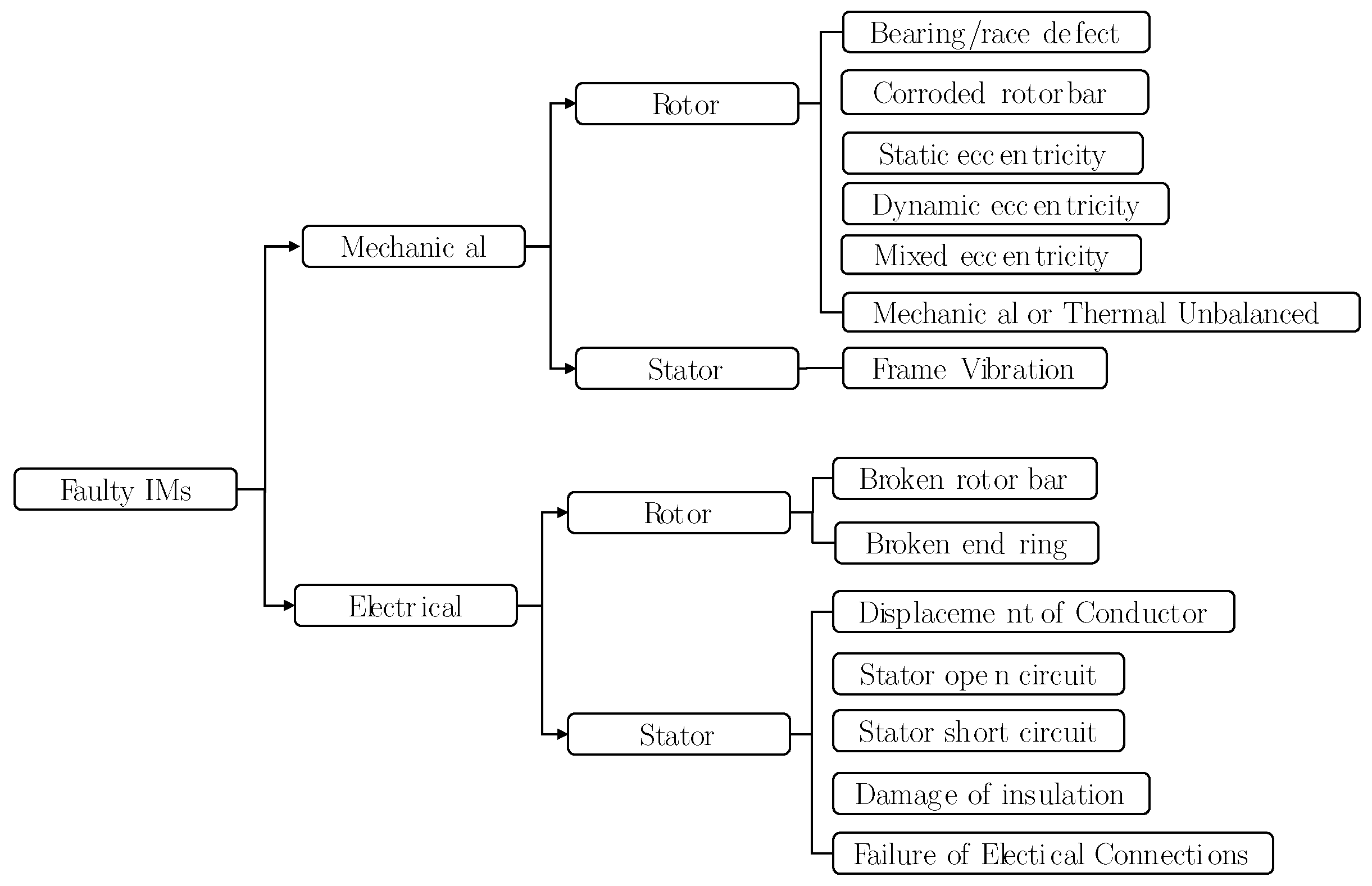
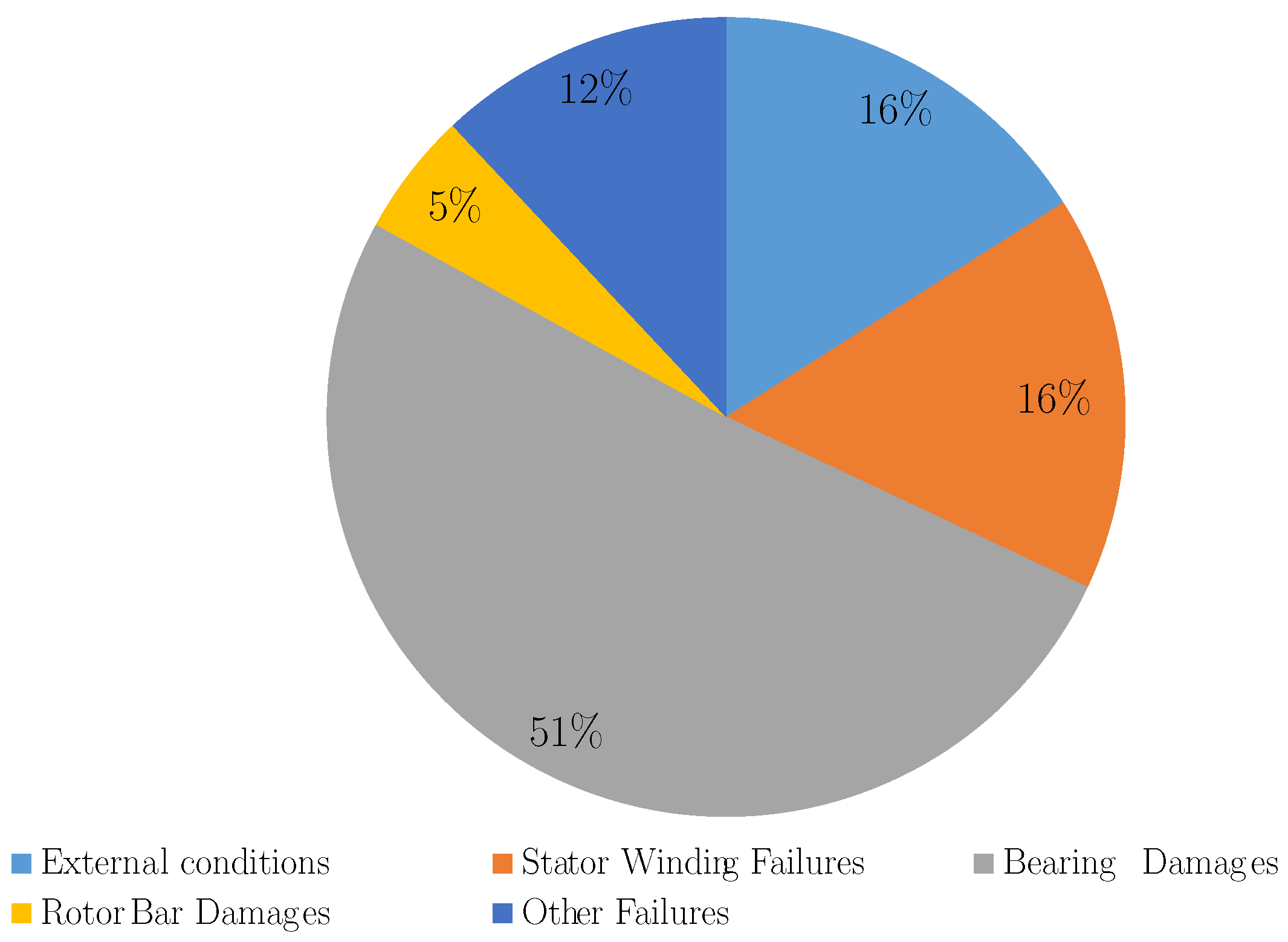
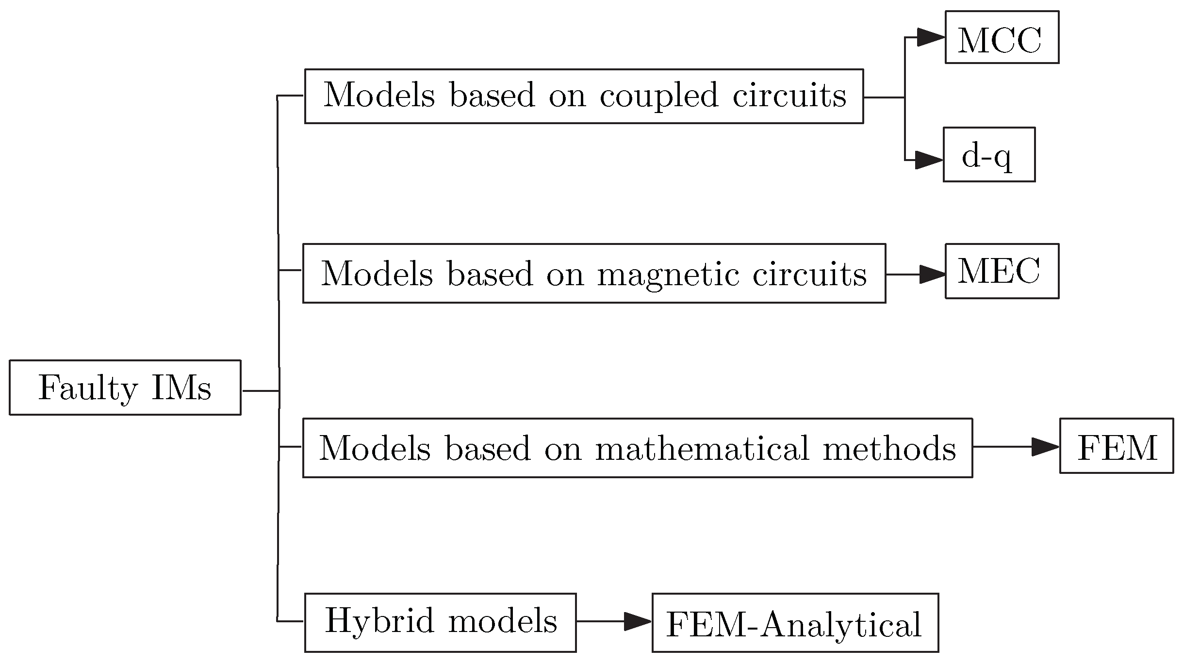
:1. Introduction
2. Models Based on Coupled Circuits
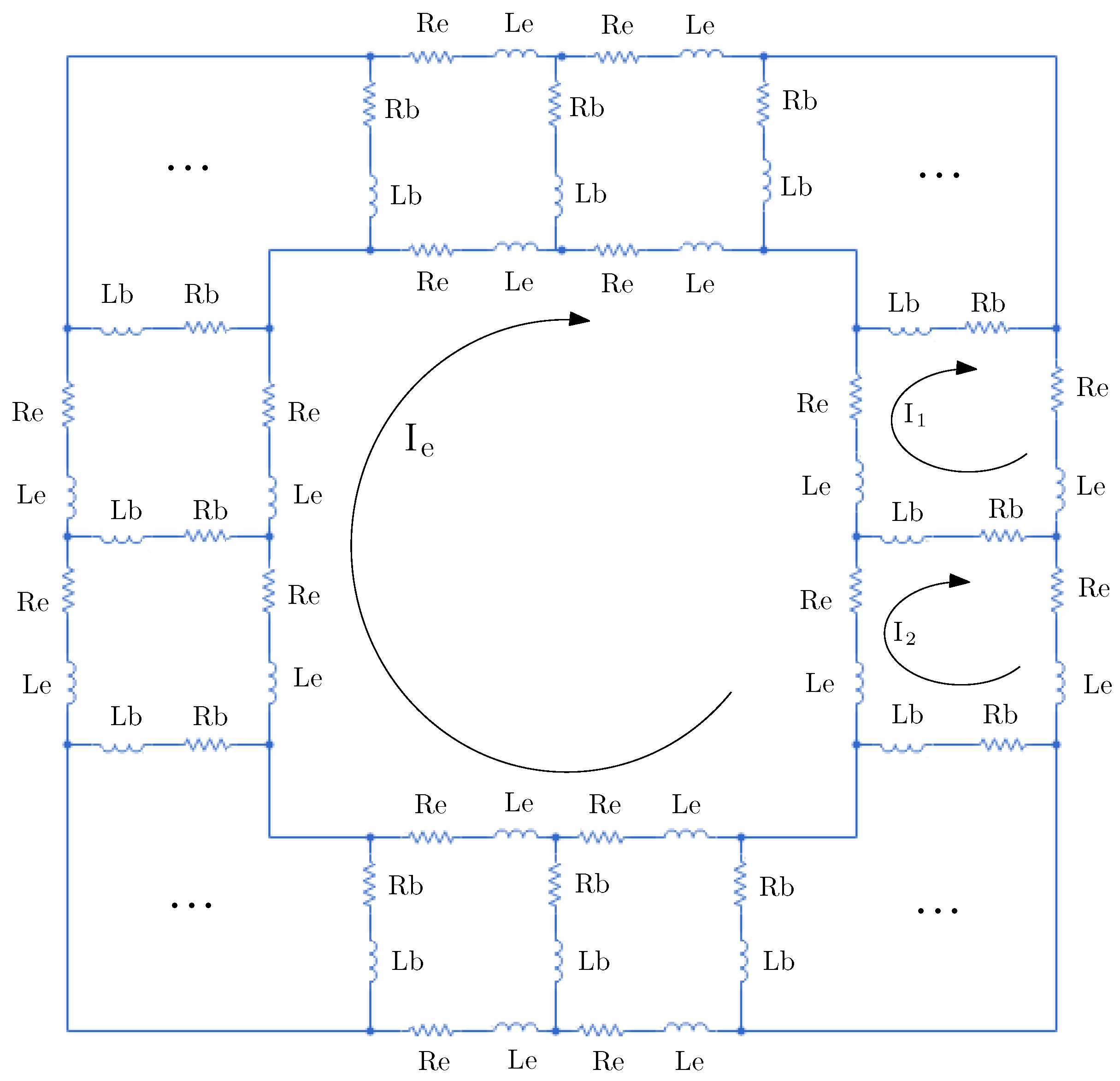
2.1. Multiple Coupled Circuit Models
2.2. d-q Models
3. Models Based on Magnetic Circuits
4. Models Based on FEM
5. Hybrid Models
6. Conclusions
Author Contributions
Funding
Conflicts of Interest
References
- Karmakar, S.; Chattopadhyay, S.; Mitra, M.; Sengupta, S. Induction Motor Diagnosis; Springer: Berlin/Heidelberg, Germany, 2016. [Google Scholar]
- Benbouzid, M.E.H. A review of induction motors signature analysis as a medium for faults detection. IEEE Trans. Ind. Electron. 2000, 47, 984–993. [Google Scholar] [CrossRef] [Green Version]
- Lannoo, J.; Vanoost, D.; Peuteman, J.; Debruyne, S.; De Gersem, H.; Pissoort, D. Improved air gap permeance model to characterise the transient behaviour of electrical machines using magnetic equivalent circuit method. Int. J. Numer. Model. Electron. Netw. Devices Fields 2020, 33, e2749. [Google Scholar] [CrossRef]
- Brkovic, A.; Gajic, D.; Gligorijevic, J.; Savic-Gajic, I.; Georgieva, O.; Di Gennaro, S. Early fault detection and diagnosis in bearings for more efficient operation of rotating machinery. Energy 2017, 136, 63–71. [Google Scholar] [CrossRef]
- Liang, X.; Edomwandekhoe, K. Condition monitoring techniques for induction motors. In Proceedings of the 2017 IEEE Industry Applications Society Annual Meeting, Cincinnati, OH, USA, 1–5 October 2017; pp. 1–10. [Google Scholar]
- Glowacz, A.; Glowacz, Z. Diagnostics of stator faults of the single-phase induction motor using thermal images, MoASoS and selected classifiers. Measurement 2016, 93, 86–93. [Google Scholar] [CrossRef]
- Delgado-Arredondo, P.A.; Morinigo-Sotelo, D.; Osornio-Rios, R.A.; Avina-Cervantes, J.G.; Rostro-Gonzalez, H.; de Jesus Romero-Troncoso, R. Methodology for fault detection in induction motors via sound and vibration signals. Mech. Syst. Signal Process. 2017, 83, 568–589. [Google Scholar] [CrossRef]
- Stone, G.C.; Sedding, H.G.; Chan, C. Experience With Online Partial-Discharge Measurement in High-Voltage Inverter-Fed Motors. IEEE Trans. Ind. Appl. 2018, 54, 866–872. [Google Scholar] [CrossRef]
- Seshadrinath, J.; Singh, B.; Panigrahi, B.K. Vibration Analysis Based Interturn Fault Diagnosis in Induction Machines. IEEE Trans. Ind. Inform. 2014, 10, 340–350. [Google Scholar] [CrossRef]
- Henao, H.; Capolino, G.; Fernandez-Cabanas, M.; Filippetti, F.; Bruzzese, C.; Strangas, E.; Pusca, R.; Estima, J.; Riera-Guasp, M.; Hedayati-Kia, S. Trends in Fault Diagnosis for Electrical Machines: A Review of Diagnostic Techniques. IEEE Ind. Electron. Mag. 2014, 8, 31–42. [Google Scholar] [CrossRef]
- Culbert, I.; Letal, J. Signature Analysis for Online Motor Diagnostics: Early Detection of Rotating Machine Problems Prior to Failure. IEEE Ind. Appl. Mag. 2017, 23, 76–81. [Google Scholar] [CrossRef]
- Gangsar, P.; Tiwari, R. Signal based condition monitoring techniques for fault detection and diagnosis of induction motors: A state-of-the-art review. Mech. Syst. Signal Process. 2020, 144, 106908. [Google Scholar] [CrossRef]
- Yin, Z.; Hou, J. Recent advances on SVM based fault diagnosis and process monitoring in complicated industrial processes. Neurocomputing 2016, 174, 643–650. [Google Scholar] [CrossRef]
- Ali, J.B.; Fnaiech, N.; Saidi, L.; Chebel-Morello, B.; Fnaiech, F. Application of empirical mode decomposition and artificial neural network for automatic bearing fault diagnosis based on vibration signals. Appl. Acoust. 2015, 89, 16–27. [Google Scholar]
- Edomwandekhoe, K.; Liang, X. Advanced feature selection for broken rotor bar faults in induction motors. In Proceedings of the 2018 IEEE/IAS 54th Industrial and Commercial Power Systems Technical Conference (I CPS), Niagara Falls, ON, Canada, 7–10 May 2018; pp. 1–10. [Google Scholar]
- Ali, M.Z.; Shabbir, M.N.S.K.; Liang, X.; Zhang, Y.; Hu, T. Machine Learning-Based Fault Diagnosis for Single- and Multi-Faults in Induction Motors Using Measured Stator Currents and Vibration Signals. IEEE Trans. Ind. Appl. 2019, 55, 2378–2391. [Google Scholar] [CrossRef]
- Kumar, R.R.; Cirrincione, G.; Cirrincione, M.; Tortella, A.; Andriollo, M. A Topological Neural Based Scheme for Classification of Faults in Induction Machines. IEEE Trans. Ind. Appl. 2020, 57, 272–283. [Google Scholar] [CrossRef]
- Ghosh, E.; Mollaeian, A.; Kim, S.; Tjong, J.; Kar, N.C. DNN-Based Predictive Magnetic Flux Reference for Harmonic Compensation Control in Magnetically Unbalanced Induction Motor. IEEE Trans. Magn. 2017, 53, 1–7. [Google Scholar] [CrossRef]
- Toma, R.N.; Prosvirin, A.E.; Kim, J.M. Bearing Fault Diagnosis of Induction Motors Using a Genetic Algorithm and Machine Learning Classifiers. Sensors 2020, 20, 1884. [Google Scholar] [CrossRef] [Green Version]
- Burriel-Valencia, J.; Puche-Panadero, R.; Martinez-Roman, J.; Sapena-Bano, A.; Pineda-Sanchez, M.; Perez-Cruz, J.; Riera-Guasp, M. Automatic fault diagnostic system for induction motors under transient regime optimized with expert systems. Electronics 2019, 8, 6. [Google Scholar] [CrossRef] [Green Version]
- Touhami, O.; Noureddine, L.; Ibtiouen, R.; Fadel, M. Modeling of the induction machine for the diagnosis of rotor defects. Part I. An approach of magnetically coupled multiple circuits. In Proceedings of the 31st Annual Conference of IEEE Industrial Electronics Society, IECON 2005, Raleigh, NC, USA, 6–10 November 2005; p. 8. [Google Scholar]
- Touhami, O.; Noureddine, L.; Ibtiouen, R.; Fadel, M. Modeling of the induction machine for the diagnosis of rotor defects. Part. II. Simulation and experimental results. In Proceedings of the 31st Annual Conference of IEEE Industrial Electronics Society 2005, IECON 2005, Raleigh, NC, USA, 6–10 November 2005; p. 6. [Google Scholar]
- Tang, J.; Chen, J.; Dong, K.; Yang, Y.; Lv, H.; Liu, Z. Modeling and Evaluation of Stator and Rotor Faults for Induction Motors. Energies 2020, 13, 133. [Google Scholar] [CrossRef] [Green Version]
- Krishna, M.S.R.; Ravi, K.S. Fault diagnosis of induction motor using Motor Current Signature Analysis. In Proceedings of the 2013 International Conference on Circuits, Power and Computing Technologies (ICCPCT), Nagercoil, India, 20–21 March 2013; pp. 180–186. [Google Scholar]
- Sapena-Bano, A.; Martinez-Roman, J.; Puche-Panadero, R.; Pineda-Sanchez, M.; Perez-Cruz, J.; Riera-Guasp, M. Induction machine model with space harmonics for fault diagnosis based on the convolution theorem. Int. J. Electr. Power Energy Syst. 2018, 100, 463–481. [Google Scholar] [CrossRef]
- Joksimovic, G.M. Double-fed Induction Machine Dynamic Modeling using Winding Function Approach. In Proceedings of the 2007 IEEE International Electric Machines Drives Conference, Antalya, Turkey, 3–5 May 2007; Volume 1, pp. 694–697. [Google Scholar]
- Yassa, N.; Rachek, M.; Houassine, H. Motor current signature analysis for the air gap eccentricity detection in the squirrel cage induction machines. Energy Procedia 2019, 162, 251–262. [Google Scholar] [CrossRef]
- Wang, C.; Wang, M.; Yang, B.; Song, K. A model-based method for bearing fault detection using motor current. J. Phys. Conf. Ser. 2020, 1650, 032130. [Google Scholar] [CrossRef]
- Joksimovic, G.M.; Durovic, M.D.; Penman, J.; Arthur, N. Dynamic simulation of dynamic eccentricity in induction machines-winding function approach. IEEE Trans. Energy Convers. 2000, 15, 143–148. [Google Scholar] [CrossRef]
- Zouzou, S.; Ghoggal, A.; Abdennacer, A.; Sahraoui, M.; Razik, H. Modeling of induction machines with skewed rotor slots dedicated to rotor faults. In Proceedings of the 2005 5th IEEE International Symposium on Diagnostics for Electric Machines, Power Electronics and Drives, Vienna, Austria, 7–9 September 2005; pp. 1–6. [Google Scholar]
- Kaikaa, M.Y.; Hadjami, M.; Khezzar, A. Effects of the simultaneous presence of static eccentricity and broken rotor bars on the stator current of induction machine. IEEE Trans. Ind. Electron. 2013, 61, 2452–2463. [Google Scholar] [CrossRef]
- Jung, J.; Kwon, B. Corrosion Model of a Rotor-Bar-Under-Fault Progress in Induction Motors. IEEE Trans. Ind. Electron. 2006, 53, 1829–1841. [Google Scholar] [CrossRef]
- Singh, A.; Grant, B.; DeFour, R.; Sharma, C.; Bahadoorsingh, S. A review of induction motor fault modeling. Electr. Power Syst. Res. 2016, 133, 191–197. [Google Scholar] [CrossRef]
- Zheng, Y.; Zhou, L.; Wang, J.; Ma, Y.; Zhao, J. Dynamic Startup Characteristics Analysis of Single-winding Pole Changing Line-start Canned Solid-Rotor Induction Motor with Squirrel-cage. In Proceedings of the 2019 22nd International Conference on Electrical Machines and Systems (ICEMS), Harbin, China, 11–14 August 2019; pp. 1–6. [Google Scholar]
- Ilamparithi, T.; Nandi, S. Comparison of results for eccentric cage induction motor using Finite Element method and Modified Winding Function Approach. In Proceedings of the 2010 Joint International Conference on Power Electronics, Drives and Energy Systems 2010 Power India, New Delhi, India, 20–23 December 2010; pp. 1–7. [Google Scholar]
- Asad, B.; Vaimann, T.; Kallaste, A.; Rassõlkin, A.; Belahcen, A. Winding Function Based Analytical Model of Squirrel Cage Induction Motor for Fault Diagnostics. In Proceedings of the 2019 26th International Workshop on Electric Drives: Improvement in Efficiency of Electric Drives (IWED), Moscow, Russia, 30 January–2 February 2019; pp. 1–6. [Google Scholar]
- Toliyat, H.A.; Lipo, T.A.; White, J.C. Analysis of a concentrated winding induction machine for adjustable speed drive applications. I. Motor analysis. IEEE Trans. Energy Convers. 1991, 6, 679–683. [Google Scholar] [CrossRef]
- Bossio, G.R.; De Angelo, C.H.; Pezzani, C.M.; Bossio, J.M.; Garcia, G.O. Evaluation of harmonic current sidebands for broken bar diagnosis in induction motors. In Proceedings of the 2009 IEEE International Symposium on Diagnostics for Electric Machines, Power Electronics and Drives, Cargese, France, 31 August–3 September 2009; pp. 1–6. [Google Scholar]
- Purvee, A.; Tsend-Ayush, E.; Erdenetsogt, N.; Morelos-Zaragoza, R. Rotor Fault Detection of Squirrel Cage Induction Motor Using Spectrum Analysis of Dynamic Simulation and Experimental Validation. In Proceedings of the 2019 IEEE Energy Conversion Congress and Exposition (ECCE), Baltimore, MD, USA, 29 September–3 October 2019; pp. 1623–1628. [Google Scholar]
- Houdouin, G.; Barakat, G.; Dakyo, B.; Destobbeleer, E. A winding function theory based global method for the simulation of faulty induction machines. In Proceedings of the IEEE International Electric Machines and Drives Conference 2003, IEMDC’03, Madison, WI, USA, 1–4 June 2003; Volume 1, pp. 297–303. [Google Scholar]
- Devanneaux, V.; Dagues, B.; Faucher, J.; Barakat, G. An accurate model of squirrel cage induction machines under stator faults. Math. Comput. Simul. 2003, 63, 377–391. [Google Scholar] [CrossRef]
- Faiz, J.; Ojaghi, M. Unified winding function approach for dynamic simulation of different kinds of eccentricity faults in cage induction machines. IET Electr. Power Appl. 2009, 3, 461–470. [Google Scholar] [CrossRef]
- PAL, R.; MOHANTY, A. A simplified dynamical model of mixed eccentricity fault in a three phase induction motor. IEEE Trans. Ind. Electron. 2020, 68, 4341–4350. [Google Scholar] [CrossRef]
- Purvee, A.; Banerjee, G. Dynamic simulation and experimental results of bearing faults of squirrel cage induction motor. In Proceedings of the 2012 IEEE International Conference on Condition Monitoring and Diagnosis, Bali, Indonesia, 23–27 September 2012; pp. 718–722. [Google Scholar]
- Ojaghi, M.; Yazdandoost, N. Winding function approach to simulate induction motors under sleeve bearing fault. In Proceedings of the 2014 IEEE International Conference on Industrial Technology (ICIT), Busan, Korea, 26 February–1 March 2014; pp. 158–163. [Google Scholar]
- Ojaghi, M.; Sabouri, M.; Faiz, J. Analytic Model for Induction Motors Under Localized Bearing Faults. IEEE Trans. Energy Convers. 2018, 33, 617–626. [Google Scholar] [CrossRef]
- Bouzid, M.; Champenois, G. An efficient, simplified multiple-coupled circuit model of the induction motor aimed to simulate different types of stator faults. Math. Comput. Simul. 2013, 90, 98–115. [Google Scholar] [CrossRef]
- Ćalasan, M.; Micev, M.; Ali, Z.M.; Zobaa, A.F.; Abdel Aleem, S.H. Parameter Estimation of Induction Machine Single-Cage and Double-Cage Models Using a Hybrid Simulated Annealing–Evaporation Rate Water Cycle Algorithm. Mathematics 2020, 8, 1024. [Google Scholar] [CrossRef]
- Toliyat, H.A.; Levi, E.; Raina, M. A review of RFO induction motor parameter estimation techniques. IEEE Trans. Energy Convers. 2003, 18, 271–283. [Google Scholar] [CrossRef]
- Lin, W.M.; Su, T.J.; Wu, R.C. Parameter identification of induction machine with a starting no-load low-voltage test. IEEE Trans. Ind. Electron. 2011, 59, 352–360. [Google Scholar] [CrossRef]
- Che, H.S.; Abdel-Khalik, A.S.; Dordevic, O.; Levi, E. Parameter estimation of asymmetrical six-phase induction machines using modified standard tests. IEEE Trans. Ind. Electron. 2017, 64, 6075–6085. [Google Scholar] [CrossRef] [Green Version]
- Yassa, N.; Rachek, M. Modeling and detecting the stator winding inter turn fault of permanent magnet synchronous motors using stator current signature analysis. Math. Comput. Simul. 2020, 167, 325–339. [Google Scholar] [CrossRef]
- Choudhary, A.; Meena, D.C.; Patra, A.K. Asynchronous Motor Modeling in Simulink for Stator and Rotor Fault Analysis. In Proceedings of the 2019 International Conference on Green and Human Information Technology (ICGHIT), Kuala Lumpur, Malaysia, 15–17 January 2019; pp. 82–85. [Google Scholar]
- Saleem, A.; Issa, R.; Tutunji, T. Hardware-in-the-loop for on-line identification and control of three-phase squirrel cage induction motors. Simul. Model. Pract. Theory 2010, 18, 277–290. [Google Scholar] [CrossRef]
- Novotny, D.; Lipo, T. Vector Control and Dynamics of AC Drives; Claredon Press: Oxford, UK, 2007. [Google Scholar]
- Guezmil, A.; Berriri, H.; Pusca, R.; Sakly, A.; Romary, R.; Mimouni, M.F. Detecting inter-turn short-circuit fault in induction machine using high-order sliding mode observer: Simulation and experimental verification. J. Control Autom. Electr. Syst. 2017, 28, 532–540. [Google Scholar] [CrossRef]
- Bangura, J.F.; Povinelli, R.J.; Demerdash, N.A.O.; Brown, R.H. Diagnostics of eccentricities and bar/end-ring connector breakages in polyphase induction motors through a combination of time-series data mining and time-stepping coupled FE-state-space techniques. IEEE Trans. Ind. Appl. 2003, 39, 1005–1013. [Google Scholar] [CrossRef]
- Samir, H.; Omar, T.; Rachid, I. Generalized two axes model of a squirrel-cage induction motor for rotor fault diagnosis. Serb. J. Electr. Eng. 2008, 5, 155–170. [Google Scholar] [CrossRef]
- Baccarini, L.M.R.; de Menezes, B.R.; Caminhas, W.M. Fault induction dynamic model, suitable for computer simulation: Simulation results and experimental validation. Mech. Syst. Signal Process. 2010, 24, 300–311. [Google Scholar] [CrossRef]
- Nemec, M.; Drobnič, K.; Fišer, R.; Ambrožič, V. Simplified model of induction machine with broken rotor bars. In Proceedings of the 2016 IEEE International Power Electronics and Motion Control Conference (PEMC), Varna, Bulgaria, 25–28 September 2016; pp. 1085–1090. [Google Scholar]
- Magagula, G.S.; Nnachi, A.F.; Akumu, A.O. Broken Rotor Bar Fault Simulation And Analysis In D-q Reference Frame. In Proceedings of the 2020 IEEE PES/IAS PowerAfrica, Nairobi, Kenya, 25–28 August 2020; pp. 1–4. [Google Scholar]
- Kang, M.; Huang, J. Simulation and analysis of squirrel cage induction machines under rotor internal faults. In Proceedings of the 2005 International Conference on Electrical Machines and Systems, Nanjing, China, 27–29 September 2005; Volume 3, pp. 2023–2027. [Google Scholar]
- Jannati, M.; Idris, N.R.N.; Salam, Z. A new method for modeling and vector control of unbalanced induction motors. In Proceedings of the 2012 IEEE Energy Conversion Congress and Exposition (ECCE), Raleigh, NC, USA, 15–20 September 2012; pp. 3625–3632. [Google Scholar]
- Bindu, S.; Thomas, V.V. Detection of Static Air-Gap Eccentricity in Three-Phase Squirrel Cage Induction Motor Through Stator Current and Vibration Analysis. In Advances in Power Systems and Energy Management; Springer: Berlin/Heidelberg, Germany, 2018; pp. 511–518. [Google Scholar]
- Bindu, S.; Thomas, V.V. A modified direct-quadrature axis model for characterization of air-gap mixed eccentricity faults in three-phase induction motor. Int. Rev. Model. Simul. 2018, 11, 359–365. [Google Scholar] [CrossRef]
- Zhang, S.; Wang, B.; Kanemaru, M.; Lin, C.; Liu, D.; Miyoshi, M.; Teo, K.H.; Habetler, T.G. Model-Based Analysis and Quantification of Bearing Faults in Induction Machines. IEEE Trans. Ind. Appl. 2020, 56, 2158–2170. [Google Scholar] [CrossRef]
- Sizov, G.Y.; Yeh, C.C.; Demerdash, N.A. Magnetic equivalent circuit modeling of induction machines under stator and rotor fault conditions. In Proceedings of the 2009 IEEE International Electric Machines and Drives Conference, Miami, FL, USA, 3–6 May 2009; pp. 119–124. [Google Scholar]
- Naderi, P.; Rostami, M.; Ramezannezhad, A. Phase-to-phase fault detection method for synchronous reluctance machine using MEC method. Electr. Eng. 2019, 101, 575–586. [Google Scholar] [CrossRef]
- Nazarzadeh, J.; Naeini, V. Magnetic reluctance method for dynamical modeling of squirrel cage induction machines. In Electric Machines and Drives; IntechOpen: Rijeka, Croatia, 2011; p. 262. [Google Scholar]
- Sudhoff, S.D.; Kuhn, B.T.; Corzine, K.A.; Branecky, B.T. Magnetic Equivalent Circuit Modeling of Induction Motors. IEEE Trans. Energy Convers. 2007, 22, 259–270. [Google Scholar] [CrossRef]
- Tavana, N.R.; Dinavahi, V. Real-time nonlinear magnetic equivalent circuit model of induction machine on FPGA for hardware-in-the-loop simulation. IEEE Trans. Energy Convers. 2016, 31, 520–530. [Google Scholar] [CrossRef]
- Han, Q.; Ding, Z.; Xu, X.; Wang, T.; Chu, F. Stator current model for detecting rolling bearing faults in induction motors using magnetic equivalent circuits. Mech. Syst. Signal Process. 2019, 131, 554–575. [Google Scholar] [CrossRef]
- Jandaghi, B.; Dinavahi, V. Real-time HIL emulation of faulted electric machines based on nonlinear MEC model. IEEE Trans. Energy Convers. 2019, 34, 1190–1199. [Google Scholar] [CrossRef]
- Naderi, P. Modified magnetic-equivalent-circuit approach for various faults studying in saturable double-cage-induction machines. IET Electr. Power Appl. 2017, 11, 1224–1234. [Google Scholar] [CrossRef]
- Alipour-Sarabi, R.; Nasiri-Gheidari, Z.; Oraee, H. Development of a Three-Dimensional Magnetic Equivalent Circuit Model for Axial Flux Machines. IEEE Trans. Ind. Electron. 2019, 67, 5758–5767. [Google Scholar] [CrossRef]
- Naderi, P.; Shiri, A. Rotor/stator inter-turn short circuit fault detection for saturable wound-rotor induction machine by modified magnetic equivalent circuit approach. IEEE Trans. Magn. 2017, 53, 1–13. [Google Scholar] [CrossRef]
- Faiz, J.; Moosavi, S.M.; Abadi, M.B.; Cruz, S.M. Magnetic equivalent circuit modelling of doubly-fed induction generator with assessment of rotor inter-turn short-circuit fault indices. IET Renew. Power Gener. 2016, 10, 1431–1440. [Google Scholar] [CrossRef]
- Faiz, J.; Ghasemi-Bijan, M.; Mahdi Ebrahimi, B. Modeling and diagnosing eccentricity fault using three-dimensional magnetic equivalent circuit model of three-phase squirrel-cage induction motor. Electr. Power Compon. Syst. 2015, 43, 1246–1256. [Google Scholar] [CrossRef]
- Naderi, P.; Fallahi, F. Eccentricity fault diagnosis in three-phase-wound-rotor induction machine using numerical discrete modeling method. Int. J. Numer. Model. Electron. Netw. Devices Fields 2016, 29, 982–997. [Google Scholar] [CrossRef]
- Faiz, J.; Ebrahimi, B.M.; Toliyat, H.A. Effect of Magnetic Saturation on Static and Mixed Eccentricity Fault Diagnosis in Induction Motor. IEEE Trans. Magn. 2009, 45, 3137–3144. [Google Scholar] [CrossRef]
- Sobczyk, T.J.; Tulicki, J.; Weinreb, K.; Mielnik, R.; Sułowicz, M. Characteristic Features of Rotor Bar Current Frequency Spectrum in Cage Induction Machine with Inner Faults. In Proceedings of the 2019 IEEE 12th International Symposium on Diagnostics for Electrical Machines, Power Electronics and Drives (SDEMPED), Toulouse, France, 27–30 August 2019; pp. 115–120. [Google Scholar]
- Constantin, A. Detection Based on Stator Current Signature of the Single and Combined Short-Circuit, Broken Bar and Eccentricity Faults in Induction Motors. In Proceedings of the 2019 11th International Symposium on Advanced Topics in Electrical Engineering (ATEE), Bucharest, Romania, 28–30 March 2019; pp. 1–6. [Google Scholar]
- Asad, B.; Eensalu, L.; Vaimann, T.; Kallaste, A.; Rassõlkin, A.; Belahcen, A. The FEM Based Modeling and Corresponding Test Rig Preparation for Broken Rotor Bars Analysis. In Proceedings of the 2019 IEEE 60th International Scientific Conference on Power and Electrical Engineering of Riga Technical University (RTUCON), Riga, Latvia, 7–9 October 2019; pp. 1–9. [Google Scholar]
- Bianchi, N. Electrical Machine Analysis Using Finite Elements; CRC Press: Boca Raton, FL, USA, 2005. [Google Scholar]
- Salon, S.J. Finite Element Analysis of Electrical Machines; Kluwer Academic Publishers Boston: Boston, MA, USA, 1995; Volume 101. [Google Scholar]
- Goktas, T.; Arkan, M.; Mamis, M.S.; Akin, B. Broken rotor bar fault monitoring based on fluxgate sensor measurement of leakage flux. In Proceedings of the 2017 IEEE International Electric Machines and Drives Conference (IEMDC), Miami, FL, USA, 21–24 May 2017; pp. 1–6. [Google Scholar]
- Sittisrijan, N.; Ruangsinchaiwanich, S. Analysis of stator current waveforms of induction motor with broken bar conditions. In Proceedings of the 2011 International Conference on Electrical Machines and Systems, Beijing, China, 20–23 August 2011; pp. 1–6. [Google Scholar]
- Viswanath, S.; Kumar, N.P.; Isha, T. Static Eccentricity Fault in Induction Motor Drive Using Finite Element Method. In Advances in Electrical and Computer Technologies; Springer: Berlin/Heidelberg, Germany, 2020; pp. 1291–1302. [Google Scholar]
- Lubin, T.; Hamiti, T.; Razik, H.; Rezzoug, A. Comparison between finite-element analysis and winding function theory for inductances and torque calculation of a synchronous reluctance machine. IEEE Trans. Magn. 2007, 43, 3406–3410. [Google Scholar] [CrossRef] [Green Version]
- Gu, B.G. Offline interturn fault diagnosis method for induction motors by impedance analysis. IEEE Trans. Ind. Electron. 2017, 65, 5913–5920. [Google Scholar] [CrossRef]
- Makhetha, E.; Muteba, M.; Nicolae, D.V. Effect of Rotor bar Shape and Stator Slot Opening on the Performance of Three Phase Squirrel Cage Induction Motors with Broken Rotor Bars. In Proceedings of the 2019 Southern African Universities Power Engineering Conference/Robotics and Mechatronics/Pattern Recognition Association of South Africa (SAUPEC/RobMech/PRASA), Bloemfontein, South Africa, 28–30 January 2019; pp. 463–468. [Google Scholar]
- Spyropoulos, D.V.; Gyftakis, K.N.; Kappatou, J.; Mitronikas, E.D. The influence of the broken bar fault on the magnetic field and electromagnetic torque in 3-phase induction motors. In Proceedings of the 2012 XXth International Conference on Electrical Machines, Marseille, France, 2–5 September 2012; pp. 1868–1874. [Google Scholar]
- Edomwandekhoe, K.; Liang, X. Current Spectral Analysis of Broken Rotor Bar Faults for Induction Motors. In Proceedings of the 2018 IEEE Canadian Conference on Electrical Computer Engineering (CCECE), Quebec, QC, Canada, 13–16 May 2018; pp. 1–5. [Google Scholar]
- Malekpour, M.; Phung, B.T.; Ambikairajah, E. Stator current envelope extraction for analysis of broken rotor bar in induction motors. In Proceedings of the 2017 IEEE 11th International Symposium on Diagnostics for Electrical Machines, Power Electronics and Drives (SDEMPED), Tinos, Greece, 29 August–1 September 2017; pp. 240–246. [Google Scholar]
- Eldeeb, H.H.; Berzoy, A.; Mohammed, O. Stator Fault Detection on DTC-Driven IM via Magnetic Signatures Aided by 2-D FEA Co-Simulation. IEEE Trans. Magn. 2019, 55, 1–5. [Google Scholar] [CrossRef]
- Fireteanu, V.; Leconte, V.; Constantin, A. Finite element analysis on early detection of the short-circuit faults in induction machines through harmonics of the stator currents or of the neighboring magnetic field. In Proceedings of the 2017 International Conference on Optimization of Electrical and Electronic Equipment (OPTIM) 2017 Intl Aegean Conference on Electrical Machines and Power Electronics (ACEMP), Brasov, Romania, 25–27 May 2017; pp. 420–427. [Google Scholar]
- Prasob, K.; Kumar, N.P.; Isha, T.B. Inter-turn short circuit fault analysis of PWM inverter fed three-phase induction motor using Finite Element Method. In Proceedings of the 2017 International Conference on Circuit, Power and Computing Technologies (ICCPCT), Kollam, India, 20–21 April 2017; pp. 1–6. [Google Scholar]
- Mafruddin, M.M.; Suwarno, S.; Abu-Siada, A. Finite Element Simulation of a 126 MW Salient Pole Synchronous Generator with Rotor Eccentricity. In Proceedings of the 2019 2nd International Conference on High Voltage Engineering and Power Systems (ICHVEPS), Denpasar, Indonesia, 1–4 October 2019; pp. 1–96. [Google Scholar]
- Sobra, J.; Kavalir, T.; Krizek, M.; Skala, B. Experimental Verification of the Finite Element Analysis of an Induction Machine with Implemented Static Eccentricity Fault. In Proceedings of the 2018 18th International Conference on Mechatronics-Mechatronika (ME), Brno, Czech Republic, 5–7 December 2018; pp. 1–5. [Google Scholar]
- Bouzida, A.; Abdelli, R.; Touhami, O.; Aibeche, A. Dynamic eccentricity fault diagnosis in induction motors using finite element method and experimental tests. Int. J. Ind. Electron. Drives 2017, 3, 199–209. [Google Scholar] [CrossRef]
- Torkaman, H.; Afjei, E.; Yadegari, P. Static, Dynamic, and Mixed Eccentricity Faults Diagnosis in Switched Reluctance Motors Using Transient Finite Element Method and Experiments. IEEE Trans. Magn. 2012, 48, 2254–2264. [Google Scholar] [CrossRef]
- Faiz, J.; Moosavi, S.M.M. Detection of mixed eccentricity fault in doubly-fed induction generator based on reactive power spectrum. IET Electr. Power Appl. 2017, 11, 1076–1084. [Google Scholar] [CrossRef]
- Gao, Y.; Liu, X.; Xiang, J. FEM Simulation-Based Generative Adversarial Networks to Detect Bearing Faults. IEEE Trans. Ind. Inform. 2020, 16, 4961–4971. [Google Scholar] [CrossRef]
- Immovilli, F.; Bianchini, C.; Cocconcelli, M.; Bellini, A.; Rubini, R. Bearing Fault Model for Induction Motor With Externally Induced Vibration. IEEE Trans. Ind. Electron. 2013, 60, 3408–3418. [Google Scholar] [CrossRef]
- Vinothraj, C.; Kumar, N.P.; Isha, T. Bearing fault analysis in induction motor drives using finite element method. Int. J. Eng. Technol. 2018, 7, 30–34. [Google Scholar] [CrossRef] [Green Version]
- Ling, Z.; Zhou, L.; Guo, S.; Zhang, Y. Equivalent circuit parameters calculation of induction motor by finite element analysis. IEEE Trans. Magn. 2014, 50, 833–836. [Google Scholar] [CrossRef]
- Bachir, S.; Tnani, S.; Trigeassou, J.; Champenois, G. Diagnosis by parameter estimation of stator and rotor faults occurring in induction machines. IEEE Trans. Ind. Electron. 2006, 53, 963–973. [Google Scholar] [CrossRef]
- Martinez, J.; Belahcen, A.; Detoni, J. A 2D magnetic and 3D mechanical coupled finite element model for the study of the dynamic vibrations in the stator of induction motors. Mech. Syst. Signal Process. 2016, 66, 640–656. [Google Scholar] [CrossRef]
- Sapena-Bano, A.; Riera-Guasp, M.; Martinez-Roman, J.; Pineda-Sanchez, M.; Puche-Panadero, R.; Perez-Cruz, J. FEM-Analytical Hybrid Model for Real Time Simulation of IMs Under Static Eccentricity Fault. In Proceedings of the 2019 IEEE 12th International Symposium on Diagnostics for Electrical Machines, Power Electronics and Drives (SDEMPED), Toulouse, France, 27–30 August 2019; pp. 108–114. [Google Scholar]
- Asad, B.; Vaimann, T.; Belahcen, A.; Kallaste, A.; Rassõlkin, A.; Iqbal, M.N. The cluster computation-based hybrid FEM–analytical model of induction motor for fault diagnostics. Appl. Sci. 2020, 10, 7572. [Google Scholar] [CrossRef]
- Sapena-Bano, A.; Chinesta, F.; Pineda-Sanchez, M.; Aguado, J.; Borzacchiello, D.; Puche-Panadero, R. Induction machine model with finite element accuracy for condition monitoring running in real time using hardware in the loop system. Int. J. Electr. Power Energy Syst. 2019, 111, 315–324. [Google Scholar] [CrossRef]
- Sapena-Bano, A.; Chinesta, F.; Puche-Panadero, R.; Martinez-Roman, J.; Pineda-Sanchez, M. Model reduction based on sparse identification techniques for induction machines: Towards the real time and accuracy-guaranteed simulation of faulty induction machines. Int. J. Electr. Power Energy Syst. 2021, 125, 106417. [Google Scholar] [CrossRef]

| Fault | References |
|---|---|
| Broken rotor bar | [23,24,30,31,32,38,39] |
| Broken end ring | [21,40] |
| Stator open circuit | [41] |
| Stator short circuit | [23,24,41] |
| Static eccentricity | [27,35,42] |
| Dynamic eccentricity | [27,29,42] |
| Mixed eccentricity | [27,43] |
| Corroded rotor bar | [32] |
| Bearing/race defect | [28,44,45,46] |
| Fault | References |
|---|---|
| Broken rotor bar | [53,58,59,60,61] |
| Broken end ring | [57,62] |
| Stator open circuit | [63] |
| Stator short circuit | [52,53,56] |
| Static eccentricity | [59,64] |
| Dynamic eccentricity | [57,59] |
| Mixed eccentricity | [65] |
| Bearing/race defect | [66] |
Publisher’s Note: MDPI stays neutral with regard to jurisdictional claims in published maps and institutional affiliations. |
© 2021 by the authors. Licensee MDPI, Basel, Switzerland. This article is an open access article distributed under the terms and conditions of the Creative Commons Attribution (CC BY) license (https://creativecommons.org/licenses/by/4.0/).
Share and Cite
Terron-Santiago, C.; Martinez-Roman, J.; Puche-Panadero, R.; Sapena-Bano, A. A Review of Techniques Used for Induction Machine Fault Modelling. Sensors 2021, 21, 4855. https://doi.org/10.3390/s21144855
Terron-Santiago C, Martinez-Roman J, Puche-Panadero R, Sapena-Bano A. A Review of Techniques Used for Induction Machine Fault Modelling. Sensors. 2021; 21(14):4855. https://doi.org/10.3390/s21144855
Chicago/Turabian StyleTerron-Santiago, Carla, Javier Martinez-Roman, Ruben Puche-Panadero, and Angel Sapena-Bano. 2021. "A Review of Techniques Used for Induction Machine Fault Modelling" Sensors 21, no. 14: 4855. https://doi.org/10.3390/s21144855
APA StyleTerron-Santiago, C., Martinez-Roman, J., Puche-Panadero, R., & Sapena-Bano, A. (2021). A Review of Techniques Used for Induction Machine Fault Modelling. Sensors, 21(14), 4855. https://doi.org/10.3390/s21144855