
Constant Optical Power Operation of an Ultraviolet LED Controlled by a Smartphone


Abstract
:1. Introduction
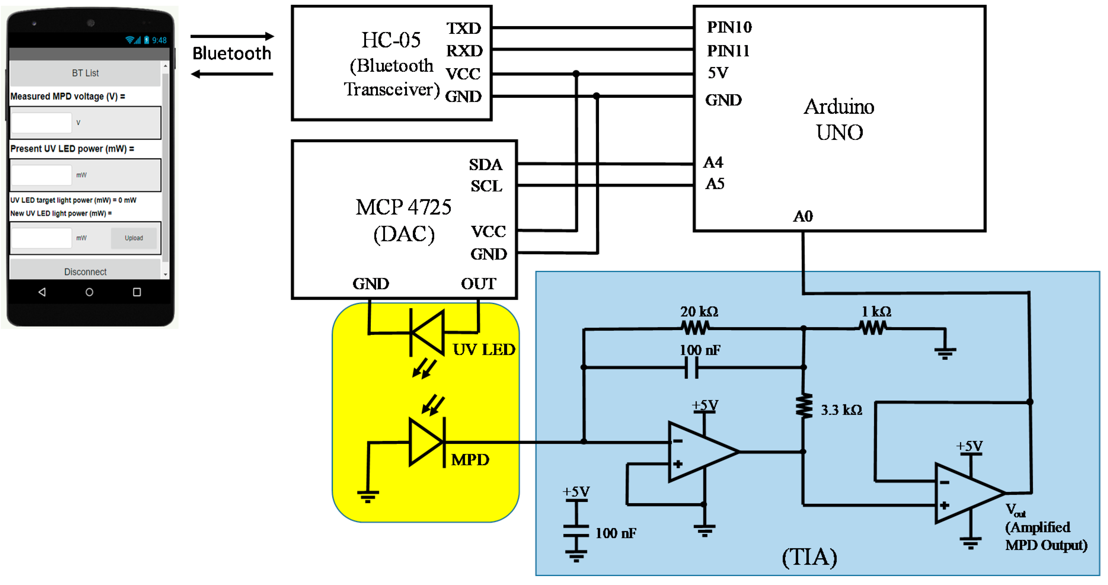
2. Module Design
3. Arduino Programming
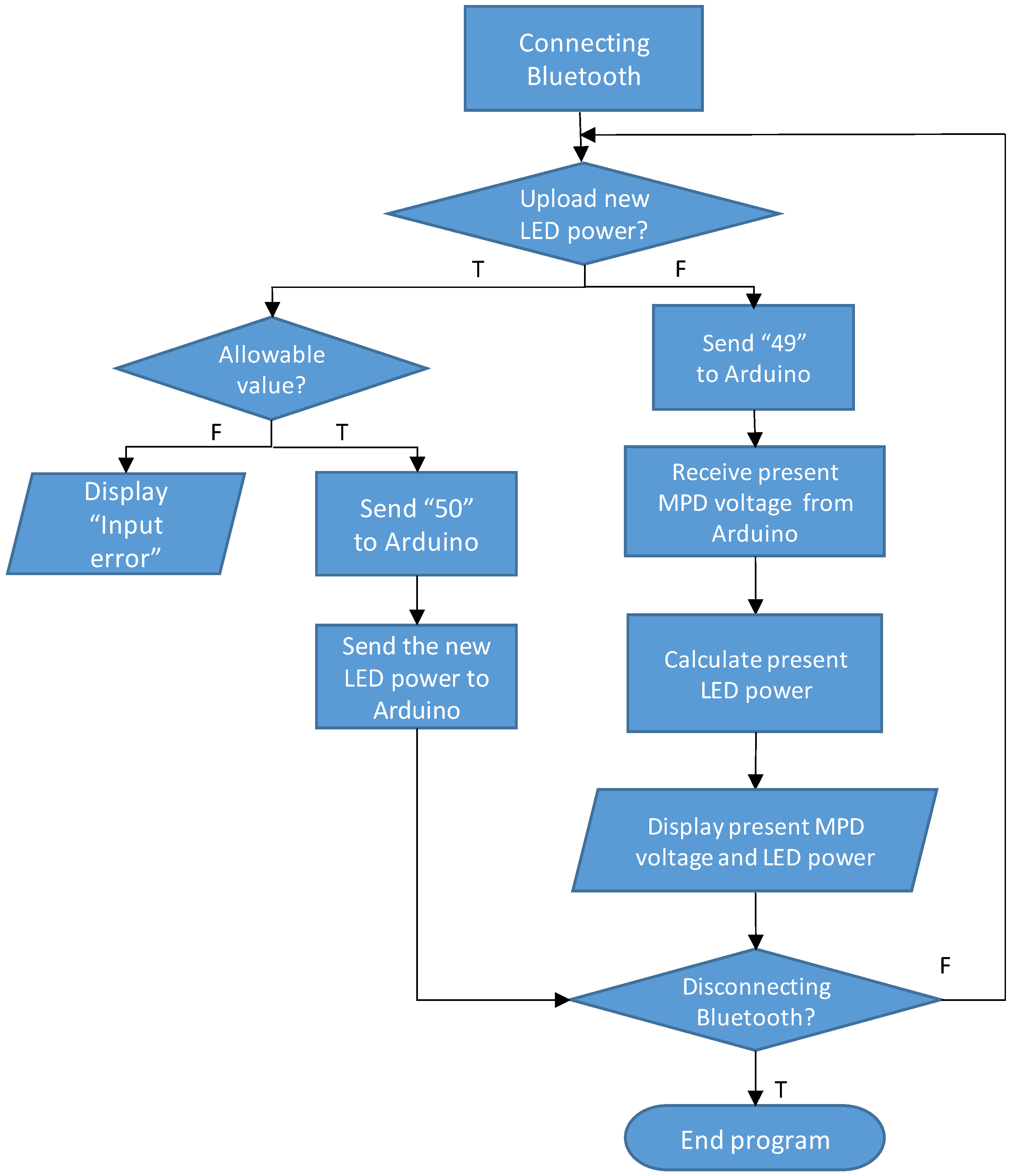
4. Android App Programming
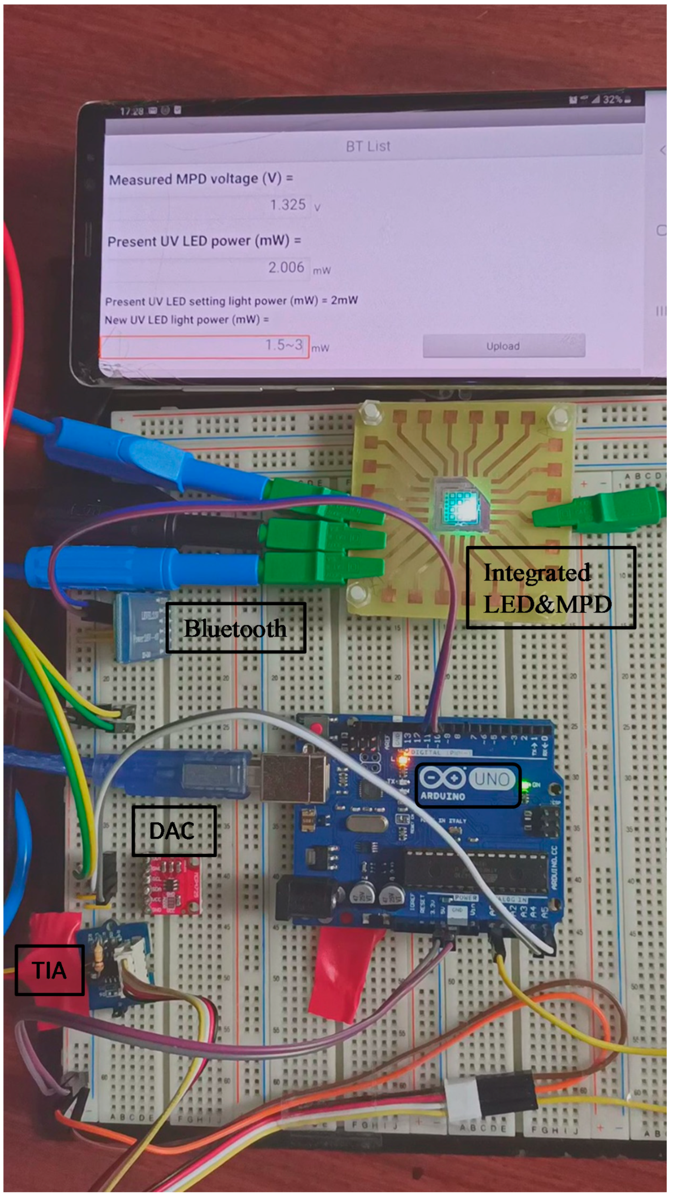
5. Results and Discussion
6. Conclusions
Author Contributions
Funding
Acknowledgments
Conflicts of Interest
References
- Glaab, J.; Ruschel, J.; Mehnke, F.; Lapeyrade, M.; Guttmann, M.; Wernicke, T.; Weyers, M.; Einfeldt, S.; Kneissl, M. Degradation behavior of AlGaN-based 233 nm deep-ultraviolet light emitting diodes. Semicond. Sci. Technol. 2018, 33, 095017. [Google Scholar] [CrossRef]
- Glaab, J.; Ruschel, J.; Kolbe, T.; Knauer, A.; Rass, J.; Cho, H.K.; Ploch, N.L.; Kreutzmann, S.; Einfeldt, S.; Weyers, M.; et al. Degradation of (In)AlGaN-Based UVB LEDs and Migration of Hydrogen. IEEE Photonics Technol. Lett. 2019, 31, 529–532. [Google Scholar] [CrossRef]
- Ma, Z.; Cao, H.; Lin, S.; Li, X.; Zhao, L. Degradation and failure mechanism of AlGaN-based UVC-LEDs. Solid State Electron. 2019, 156, 92–96. [Google Scholar] [CrossRef]
- Tchernycheva, M.; Messanvi, A.; Bugallo, A.L.; Jacopin, G.; Lavenus, P.; Rigutti, L.; Zhang, H.; Halioua, Y.; Julien, F.H.; Eymery, J.; et al. Integrated photonic platform based on InGaN/GaN nanowire emitters and detectors. Nano Lett. 2014, 14, 3515–3520. [Google Scholar] [CrossRef] [PubMed]
- Jiang, Z.; Atalla, M.R.M.; You, G.; Wang, L.; Li, X.; Liu, J.; Elahi, A.M.; Wei, L.; Xu, J. Monolithic integration of nitride light emitting diodes and photodetectors for bi-directional optical communication. Opt. Lett. 2014, 39, 5657–5660. [Google Scholar] [CrossRef] [PubMed]
- Wang, Y.; Zhu, G.; Cai, W.; Gao, X.; Yang, Y.; Yuan, J.; Shi, Z.; Zhu, H. On-chip photonic system using suspended p-n junction InGaN/GaN multiple quantum wells device and multiple waveguides. Appl. Phys. Lett. 2016, 108, 162102. [Google Scholar] [CrossRef]
- Shi, Z.; Gao, X.; Yuan, J.; Zhang, S.; Jiang, Y.; Zhang, F.; Jiang, Y.; Zhu, H.; Wang, Y. Transferrable monolithic III-nitride photonic circuit for multifunctional optoelectronics. Appl. Phys. Lett. 2017, 111, 241104. [Google Scholar] [CrossRef]
- Wang, Y.; Wang, S.; Ni, S.; Wang, W.; Shi, Z.; Yuan, J.; Zhu, H. On-chip multicomponent system made with vertical structure quantum well diode. Semicond. Sci. Technol. 2019, 34, 065017. [Google Scholar] [CrossRef]
- Li, K.H.; Cheung, Y.F.; Fu, W.Y.; Wong, K.K.Y.; Choi, H.W. Monolithic integration of GaN-on-sapphire light-emitting diodes, photodetectors, and waveguides. IEEE J. Sel. Top. Quantum Electron. 2018, 24, 3801706. [Google Scholar] [CrossRef]
- Li, K.H.; Fu, W.Y.; Cheung, Y.F.; Wong, K.K.Y.; Wang, Y.; Lau, K.M.; Choi, H.W. Monolithically integrated InGaN/GaN light-emitting diodes, photodetectors, and waveguides on Si substrate. Optica 2018, 5, 564–569. [Google Scholar] [CrossRef]
- Liu, C.; Cai, Y.; Jiang, H.; Lau, K.M. Monolithic integration of III-nitride voltage controlled light emitters with dual-wavelength photodiodes by selective-area epitaxy. Opt. Lett. 2018, 43, 3401–3404. [Google Scholar] [CrossRef] [PubMed] [Green Version]
- Li, X.; Hussain, B.; Kang, J.; Kwok, H.S.; Yue, C.P. Smart µLED Display-VLC System with a PD-Based/Camera-Based Receiver for NFC Applications. IEEE Photonics J. 2019, 11, 7901008. [Google Scholar]
- Lyu, Q.; Jiang, H.; Lau, K.M. Monolithic integration of ultraviolet light emitting diodes and photodetectors on a p-GaN/AlGaN/GaN/Si platform. Opt. Express 2021, 29, 8358–8364. [Google Scholar] [CrossRef] [PubMed]
- Sekiguchi, H.; Yasunaga, H.; Tsuchiyama, K.; Nitta, R. Neural optical probe with monolithically integrated intensity-monitoring μLED and polymer waveguide for optogenetics. Electron. Lett. 2019, 55, 619–621. [Google Scholar] [CrossRef]
- Yeh, P.S.; Chiu, Y.-C.; Wu, T.-C.; Chen, Y.-X.; Wang, T.-H.; Chou, T.-C. Monolithic integration of GaN-based phototransistors and light-emitting diodes. Opt. Express 2019, 27, 29854–29862. [Google Scholar] [CrossRef] [PubMed]
- Chiu, Y.-C.; Yeh, P.S.; Wang, T.-H.; Chou, T.-C.; Wu, C.-Y.; Zhang, J.-J. An ultraviolet sensor and indicator module based on p–i–n photodiodes. Sensors 2019, 19, 4938. [Google Scholar] [CrossRef] [PubMed] [Green Version]
- Chen, C.-H.; Zhang, J.-J.; Wang, C.-H.; Chou, T.-C.; Chan, R.-X.; Yeh, P.S. Output Power Monitoring of Ultraviolet Light-Emitting Diodes via Sapphire Substrate. Photonics 2020, 7, 63. [Google Scholar] [CrossRef]
- Chen, C.-H.; Zhang, J.-J.; Wang, C.-H.; Chou, T.-C.; Chan, R.-X.; Yeh, P.S. On-Chip Power Monitoring of Ultraviolet LEDs. In Proceedings of the 25th OptoElectronics and Communications Conference (OECC), Taipei, Taiwan, 4–8 October 2020; p. 22. [Google Scholar]
- Yin, J.; An, X.; Chen, L.; Li, J.; Wu, J.; Luo, Y.; Wang, Q.; Yu, H.; Li, K.H. Phosphor-Based InGaN/GaN White Light-Emitting Diodes with Monolithically Integrated Photodetectors. IEEE Trans. Electron Devices 2021, 68, 132–137. [Google Scholar] [CrossRef]
- Ishigaki, Y.; Matsumoto, Y.; Ichimiya, R.; Tanaka, K. Development of Mobile Radiation Monitoring System Utilizing Smartphone and Its Field Tests in Fukushima. IEEE Sens. J. 2013, 13, 3520–3526. [Google Scholar] [CrossRef]
- Arduino. Available online: https://store.arduino.cc/usa/arduino-uno-rev3/ (accessed on 20 February 2020).
- Components101. Available online: https://components101.com/wireless/hc-05-bluetooth-module/ (accessed on 24 February 2020).
- Massachusetts Institute of Technology. Available online: https://appinventor.mit.edu/ (accessed on 25 February 2020).
- Park, D.-H.; Oh, S.-T.; Lim, J.-H. Development of UVB LED Lighting System Based on UV Dose Calculation Algorithm to Meet Individual Daily UV Dose. Appl. Sci. 2019, 9, 2479. [Google Scholar] [CrossRef] [Green Version]


| Parameters | Value | Unit |
|---|---|---|
| Operating Voltage | 5 | V |
| Input Voltage (recommended) | 7–12 | V |
| Input Voltage (limit) | 6–20 | V |
| Digital I/O Pins | 14 | |
| Analog Input Pins | 6 | |
| DC Current per I/O Pin | 20 | mA |
| DC Current for 3.3 V Pin | 50 | mA |
| Flash Memory | 32 | KB |
| SRAM | 2 | KB |
| EEPROM | 1 | KB |
| Clock Speed | 16 | MHz |
| LED_BUILTIN | 13 | (Pin #) |
| Length × Width | 68.6 × 53.4 | mm2 |
| Weight | 25 | g |
| Parameters | Value | Unit |
|---|---|---|
| Operating Voltage | 4–6 | V |
| Operating Current | 30 | mA |
| Range | <100 | m |
| Compatibility | Serial communication (USART) and TTL | |
| Protocol | IEEE 802.15.1 | |
| Operating Mode | Master, Slave or Master/Slave | |
| Supported Baud Rate | 9600, 19,200, 38,400, 57,600, 115,200, 230,400, 460,800 |
Publisher’s Note: MDPI stays neutral with regard to jurisdictional claims in published maps and institutional affiliations. |
© 2021 by the authors. Licensee MDPI, Basel, Switzerland. This article is an open access article distributed under the terms and conditions of the Creative Commons Attribution (CC BY) license (https://creativecommons.org/licenses/by/4.0/).
Share and Cite
Chen, C.-H.; Zhang, J.-J.; Wang, C.-H.; Chang, Y.-C.; Yeh, P.S. Constant Optical Power Operation of an Ultraviolet LED Controlled by a Smartphone. Sensors 2021, 21, 4707. https://doi.org/10.3390/s21144707
Chen C-H, Zhang J-J, Wang C-H, Chang Y-C, Yeh PS. Constant Optical Power Operation of an Ultraviolet LED Controlled by a Smartphone. Sensors. 2021; 21(14):4707. https://doi.org/10.3390/s21144707
Chicago/Turabian StyleChen, Ching-Hua, Jia-Jun Zhang, Chang-Han Wang, Yu-Chia Chang, and Pinghui S. Yeh. 2021. "Constant Optical Power Operation of an Ultraviolet LED Controlled by a Smartphone" Sensors 21, no. 14: 4707. https://doi.org/10.3390/s21144707
APA StyleChen, C.-H., Zhang, J.-J., Wang, C.-H., Chang, Y.-C., & Yeh, P. S. (2021). Constant Optical Power Operation of an Ultraviolet LED Controlled by a Smartphone. Sensors, 21(14), 4707. https://doi.org/10.3390/s21144707