Article

Sensorless LC Filter Implementation for Permanent Magnet Machine Drive Using Observer-Based Voltage and Current Estimation

Department of Mechanical Engineering, National Taiwan University, No.1, Sec. 4, Roosevelt Road, Taipei 10617, Taiwan
*
Author to whom correspondence should be addressed.
Sensors 2021, 21(11), 3596; https://doi.org/10.3390/s21113596
Submission received: 7 April 2021 / Revised: 30 April 2021 / Accepted: 3 May 2021 / Published: 21 May 2021
(This article belongs to the Section Electronic Sensors)

Abstract

:
For pulse width modulation (PWM) inverter drives, an LC filter can cascade to a permanent magnet (PM) machine at inverter output to reduce PWM-reflected current harmonics. Because the LC filter causes resonance, the filter output current and voltage are required for the sensorless field-oriented control (FOC) drive. However, existing sensors and inverters are typically integrated inside commercial closed-form drives; it is not possible for these drives to obtain additional filter output signals. To resolve this integration issue, this paper proposes a sensorless LC filter state estimation using only the drive inside current sensors. The design principle of the LC filter is first introduced to remove PWM current harmonics. A dual-observer is then proposed to estimate the filter output current and voltage for the sensorless FOC drive. Compared to conventional model-based estimation, the proposed dual-observer demonstrates robust estimation performance under parameter error. The capacitor parameter error shows a negligible influence on the proposed observer estimation. The filter inductance error only affects the capacitor current estimation at high speed. The performance of the sensorless FOC drive using the proposed dual-observer is comparable to the same drive using external sensors for filter voltage and current measurement. All experiments are verified by a PM machine with only 130 μH phase inductance.

1. Introduction

Compared to conventional industrial PM machines, low-inductance machines have a lower inductive voltage and lower back electromotive force (EMF) voltage drop. These machines are suitable for high-speed applications under volume limitation; e.g., drones, spindles and compressors [1,2,3]. However, considering PWM voltage control, visible switching-reflected current harmonics occur on these low-inductance machines [4]. Although the bus voltage usage is improved at high speed, PWM inverter-reflected current harmonics increase the machine iron loss and cause rotor thermal issues [5,6].
LC filters can be installed in PM machine drives for the reduction of PWM current harmonics. Because LC filters do not include resistances, there is a resulting voltage and current distortion, especially for operation near filter resonance. Circulating currents are induced between the inverter and LC filter. In this case, active damping compensation is used to minimize the filter-reflected current/voltage distortion under the FOC drive. In [7,8,9,10], a cascaded controller with both an external current loop and an internal voltage loop is proposed in an induction machine for active damping compensation. However, three voltage sensors and two current sensors are required, with considerable cost. The authors of [11,12,13,14] simplify this cascaded control topology by using a simple current controller. In contrast to the voltage and current control in [7,8,9], only either the capacitor voltage or the current is closed-loop regulated. In this case, the LC filter parameters are required to maintain the active damping performance. Furthermore, for high-speed machine operation, the LC filter causes additional phase delay on machine currents. In [15,16], a discretized voltage model is proposed for digital delay compensation. A PWM inverter can achieve the current regulation on an RL load with 400 Hz frequency. Among these active damping compensations, it is noted that capacitor currents/voltages and inductor output machine currents are required for the FOC drive and active damping compensation.
For a sensorless machine drive, the inductor output machine current and capacitor voltage must be known for machine current regulation and rotor position estimation. The filter output voltage and current can be obtained by external sensors or estimated by state observers. In general, current/voltage sensors and inverters are typically integrated inside commercial closed-form drives. Additional inverter hardware modification is necessary if external sensors are selected for an FOC drive with an LC filter [17,18]. In contrast, sensorless observer-based estimation is preferred because only the inverter inside the current sensors is used for filter state estimation. In [19], the capacitor current is estimated using an LC filter observer based on the filter output current measurement. Although no voltage sensor is present, three current sensors outside the inverter are added for the observer estimation. To position sensorless FOC drives, the LC filter is also attached for current regulation [5]. However, similar to [19], filter output currents are measured in order to estimate the machine EMF voltage. In [20], with an LC filter, the direct torque and flux control is implemented for the machine drive. Considering the filter effect on the drive, several corrections are added to correct flux and torque commands. More importantly, this direct torque control still requires filter output currents to estimate the machine flux. From the review of these LC filter-related works, the integration of a filter on closed-form drives without external current sensors is desired for high-performance machine control.
This paper proposes a sensorless LC filter implementation for an FOC drive using only the inverter inside current sensors for the filter current and voltage estimation. In [21], a sensorless LC filter state estimation using only the closed-form drive inside current sensors is developed; however, only the preliminary observer topology is illustrated, neglecting various LC filter cross-coupling effects. These coupling issues including the parameter sensitivity on the filter state estimation are fully investigated here. In this paper, a dual-observer topology is proposed to estimate the filter inductor current and capacitor voltage for both current regulation and position estimation, respectively. Compared to conventional model-based filter voltage and current estimation, the proposed dual-observer can reduce the filter parameter sensitivity, resulting in better state estimation performance. Based on experimental results, a comparable FOC drive is developed and compared to the same drive using external sensors for filter voltage and current measurement. All the tests are verified on a 105 W PM machine with only 130 μH phase inductance.

2. LC Filter Design Principle

This section explains the selection of the LC filter on the PM machine FOC drive. Figure 1 illustrates the overall PWM inverter including an output LC filter. For the PWM machine drive, the LC filter along with the machine stator windings can be viewed as an LCL filter. To remove PWM-reflected current harmonics on the machine, the equivalent resonant frequency ffilter of the LCL filter can be selected based on the critical resonance frequency fcrit. As reported in [22], fcrit is suggested by
f crit = f sample 6 = f PWM 6   ( assuming   f sample =   f PWM )
where fsample is the controller sample frequency synchronized to PWM frequency fPWM. To maintain the dynamic response of machine control, the resonant frequency ffilter should be designed higher than fcrit. On the other hand, ffilter must be lower than half of fsample for the purpose of reducing the PWM-reflected current harmonics. In this paper, fsample and fcrit are 10 kHz and 1.667 kHz, respectively. However, the high fcrit might cause a challenge regarding the filter state estimation for the proposed senseless integration of the LC filter and FOC drive. Considering the available specification of inductances and capacitors, the resonant frequency ffilter is selected at 2.9 kHz based on the above criteria.
After the determination of ffilter, the individual filter inductance and capacitor value are then selected according to the requirements of the machine phase current ripples. In [23,24], the relationship between the inductor current ripple ΔIL and filter inductance can be shown to be
Δ I L = 1 8 V C L f s a m p l e
where Vc is the corresponding capacitor voltage. To reach a tolerable current ripple of around 5%, the filter inductance is designed at 1.2 mH, where the resulting capacitor is 25.8 μF. Considering the accessibility of LC components in the market, the filter inductance is re-selected at 1 mH, giving a resonant frequency of 2.92 kHz and current ripple of around 6.31%.

3. Machine Drive with LC Filter

This section explains the improvement of the low-inductance PM machine using the LC filter to reduce PWM current harmonics. For variable-frequency drive applications, the positioning of the senseless FOC drive is applied. As seen for the proposed machine drive with an LC filter in Figure 1, ILA/ILB/ILC are the inverter A/B/C-phase currents across three filter inductances, respectively, ICA/ICB/ICC are the phase currents across filter capacitors, and VCA/VCB/VCC are the phase voltages on filter capacitors. Besides, IA/IB/IC are the inductor output currents flowing across the machine phase windings.
It is noteworthy that, for standard machine drives, only the currents of ILA/ILB/ILC output from the inverter can be measured using existing current sensors. Considering the influence of the LC filter, machine phase voltages and currents can be affected by the capacitor voltages VCA/VCB/VCC and currents ICA/ICB/ICC. In this case, the PM machine model can be modified by
V C A = R s ( I L A I C A ) + L s d ( I L A I C A ) d t + ω e λ p m _ A V C B = R s ( I L B I C B ) + L s d ( I L B I C B ) d t + ω e λ p m _ B V C C = R s ( I L C I C C ) + L s d ( I L C I C C ) d t + ω e λ p m _ C
where Rs and Ls are the PM machine phase resistance and inductance, respectively, assuming no saliency for simplicity, and λpm_Apm_Bpm_C are the corresponding phase magnet flux linkages. For the senseless FOC drive, the knowledge of capacitor currents ICA/ICB/ICC and voltages VCA/VCB/VCC is required for both the current regulation and EMF-based position estimation. Table 1 lists the test PM machine specification. The rated speed is 42 krpm with 700 Hz electric frequency. It is noted that the phase inductance is only 130 μH. The visible PWM current harmonics are expected during the operation of the FOC drive. In the next section, the observer-based estimation of capacitor voltages and currents is explained using only the available measurable current signals for the drive: ILA/ILB/ILC.

4. Filter Voltage and Current Estimation

This section explains the estimation of the capacitor currents ICA/ICB/ICC and voltages VCA/VCB/VCC using the proposed dual-observer. Figure 2 demonstrates the signal process for the proposed senseless FOC drive with an LC filter. Considering the operation of the FOC drive at high speed, the proposed dual-observer is developed in a dq machine rotor-referred synchronous frame. In this case, all voltages/currents are transferred to DC signals, which are suited for closed-loop current regulation. This dual-observer consists of both a capacitor voltage observer and capacitor current observer for the estimation of V ^ Cdq , I ^ Cdq and I ^ dq . For the senseless FOC drive, the estimated machine dq currents I ^ dq are used for the current regulation. Besides, the estimated capacitor voltages V ^ Cdq should be applied for machine EMF estimation and thus rotor position estimation.

4.1. Capacitor Voltage Estimation

Figure 2 (bottom-left) denotes the proposed capacitor voltage observer. Assuming that the inverter deadtime is negligible, the inverter voltage commands V dq can contribute to both the capacitor voltages VCdq and inductor voltages VLdq. Under this effect, the dynamic model of capacitor voltage is illustrated by
[ V C d V C q ] = [ V d V q ] [ V L d V L q ] = [ V d V q ] [ R f I L d + L f d I L d d t L f ω e I L q R f I L q + L f d I L q d t + L f ω e I L d ]
Based on (4), the capacitor voltage VCdq can be directly estimated by
[ V ^ C d V ^ C q ] = [ V d V q ] [ R ^ f I L d + L ^ f d I L d d t L ^ f ω ^ e I L q R ^ f I L q + L ^ f d I L q d t + L ^ f ω ^ e I L d ]
where V ^ Ldq is the estimated dq inductance voltage, L f ^ and R f ^ are the estimated filter inductance and parasitic resistance, and ω e ^ is the estimated rotor speed. Equation (6) denotes the estimation accuracy of V ^ Cdq in the S-domain for the following parameter sensitivity analysis comparing to the proposed observer estimation.
[ V ^ C d _ e r r ( s ) V ^ C q _ e r r ( s ) ] = [ V C d ( s ) V ^ C d ( s ) V C q ( s ) V ^ C q ( s ) ] = [ ( R f R ^ f ) ( L f L ^ f ) s ( R f R ^ f ) ( L f L ^ f ) s ] [ I L d ( s ) I L q ( s ) ] + [ ( L f ω e L ^ f ω ^ e ) ( L f ω e L ^ f ω ^ e ) ] [ I L q ( s ) I L d ( s ) ]
It is noted that the error of V Cdq_err   =   V Cdq     V ^ Cdq in Equation (6) is designed to analyze the accuracy of V ^ Cdq . Considering perfect parameters of R f ^   =   R f and L f ^   =   L f , VCdq_err should be zero for all operation conditions. Figure 3 simulates the estimation accuracy of |VCdq_err(jω)/ILdp(jω)|. In this figure, different absolute magnitudes under different operating frequencies are calculated. The parameter errors of R f ^ and L f ^ are calculated based on Equation (6). As seen in Figure 3a, VCdq_err is strongly affected by the R f ^ error independent of the operating frequencies. In contrast, in (b), the influence of the L f ^ error on VCdq_err increases as frequency increases. Besides, in (c), the inductor cross-coupling voltage also results in a constant error of VCdq_err independent of the operating frequency. Considering the direct capacitor voltage estimation in Equation (5), it is concluded that V ^ Cdq estimation accuracy is strongly dependent on the inductor parameters R f ^ and L f ^ .
In this paper, the closed-loop observer is developed to reduce the parameter sensitivity through the feedback control of ILdq. Figure 4 illustrates the first closed-loop observer in the S-domain for the capacitor voltage estimation. In this observer, the inputs are the inductor-measured dq currents ILdq while the observer outputs are the estimated dq capacitor voltages V ^ Cdq . Besides, the observer controller CV(s) and feedforward voltage inputs V CFF_V are designed based on
C V ( s ) = K p _ V s + K i _ V s
[ V C F F _ V d V C F F _ V q ] = [ V d V q ] + [ V ^ c r o s s _ d V ^ c r o s s _ q ] = [ V d V q ] + [ L ^ f ω ^ e I L q L ^ f ω ^ e I L d ]
where Kp_V and Ki_V are the proportional and integral gain of the closed-loop observer, respectively. Based on closed-loop regulation, V ^ Cdq can be modeled by the external voltage disturbance. Under this effect, the capacitor voltages VCdq can be estimated by
[ V ^ C d ( s ) V ^ C q ( s ) ] = K p _ V [ I L d ( s ) I ^ L d ( s ) I L q ( s ) I ^ L q ( s ) ] + K i _ V s [ I L d ( s ) I ^ L d ( s ) I L d ( s ) I ^ L d ( s ) ]
As seen from the signal process in Figure 4, the overall dynamic model of V ^ Cdq can be formulated by
[ V ^ C d ( s ) V ^ C q ( s ) ] = ( K p _ V s + K i _ V s ) ( L f s 2 + ( R f + K p _ V ) s + K i _ V L ^ f s 2 + ( R ^ f + K p _ V ) s + K i _ V 1 ) [ I L d ( s ) I L q ( s ) ] + K p _ V s + K i _ V L ^ f s 2 + ( R ^ f + K p _ V ) s + K i _ V ( L ^ f ω ^ e L f ω e ) [ I L q ( s ) I L d ( s ) ] + K p _ V s + K i _ V L ^ f s 2 + ( R ^ f + j ω e L ^ f + K p _ V ) s + K i _ V [ V C d ( s ) V C q ( s ) ]
In Equation (10), the estimated V ^ Cdq consists of three terms: the first two terms are proportional to ILdq. If both R f ^ = Rf and L f ^ = Lf, these two terms disappear. In contrast, the third term is proportional to the actual capacitor voltages VCdq. This term is independent of the parameter errors at low frequency. Considering the filter parameter errors, the estimation accuracy of proposed observer can be represented by
[ V C d _ e r r ( s ) V C q _ e r r ( s ) ] = ( K p _ V s + K i _ V s ) ( L f s 2 + ( R f + K p _ V ) s + K i _ V L ^ f s 2 + ( R ^ f + K p _ V ) s + K i _ V 1 ) [ I L d ( s ) I L q ( s ) ] + K p _ V s + K i _ V L ^ f s 2 + ( R ^ f + K p _ V ) s + K i _ V ( L ^ f ω ^ e L f ω e ) [ I L q ( s ) I L d ( s ) ]
Comparing the proposed estimation error in Equation (11) to open-loop direct estimation in Equation (6), the estimation accuracy of V ^ Cdq is related to both the parameters R f ^ / L f ^ and controller gains Kp_V/Ki_V. By properly designing Kp_V and Ki_V, it is clear that the parameter sensitivity on V ^ Cdq can be improved.
Figure 3 also illustrates the same estimation accuracy of |VCdq_err(jω)/ILdp(jω)| based on the proposed closed-loop voltage observer. In this simulation, Kp_V and Ki_V are selected to achieve a 100 Hz bandwidth considering high-frequency noise reduction. Considering the R f ^ parameter error in Figure 3a, VCdq_err is reduced when the operating frequency is beyond the observer bandwidth, as presented by the dashed lines. Besides, for the L f ^ error resulting from self-inductance in (b) and cross-inductance in (c), VCd_err also maintains constant values or decreases beyond the observer bandwidth. By applying the proposed voltage observer in Figure 4, it is shown that the influence of filter parameter errors on V ^ Cdq is reduced due to the closed-loop control regulation.

4.2. Capacitor Current Estimation

This section explains the capacitor current ICdq and machine current Idq estimation using the proposed capacitor current observer in Figure 2. On the basis, the capacitor current ICdq can be estimated through the capacitor model. It is shown by
[ I C d I C q ] = [ I L d I L q ] [ I d I q ] = [ C p d V C d d t C p ω e V C q C p d V C q d t + C p ω e V C d ]
In Equation (12), the machine currents can also be obtained once capacitor currents are estimated, whereby I ^ dq   =   I Ldq     I ^ Cdq . Thus, the proposed current observer is focused on I ^ Cdq for simplicity. A straightforward way of achieving I ^ Cdq estimation can be developed based on Equation (13).
[ I ^ C d I ^ C q ] = [ C ^ p d V ^ C d d t C ^ p ω ^ e V ^ C q C ^ p d V ^ C q d t + C ^ p ω ^ e V ^ C d ]
where C p ^ is the estimated capacitor value. In Equation (13), I ^ Cdq estimation is dependent on both C p ^ and V ^ Cdq , which are estimated from the prior voltage observer. As mentioned in Figure 3, the accuracy of V ^ Cdq is dependent on the inductor parameters R ^ f and L ^ f . In order to evaluate the influence of R ^ f and L ^ f errors on I ^ Cdq , V ^ Cdq in Equation (13) is replaced by Equation (5), as derived by
[ I ^ C d I ^ C q ] = C ^ p [ d V d d t ω ^ e V q d V q d t + ω ^ e V d ] + C ^ p R ^ f [ d I L d d t d I L q d t ] + C ^ p L ^ f [ d 2 I L d d t 2 + ω ^ e d I L q d t d 2 I L q d t 2 ω ^ e d I L d d t ] + C ^ p R ^ f [ ω ^ e I L q ω ^ e I L d ] + C ^ p L ^ f [ ω ^ e d I L q d t + ω ^ e 2 I L d ω ^ e d I L d d t ω ^ e 2 I L q ]
Similar to Equation (6), the I ^ Cdq estimation accuracy can be analyzed in the S-domain based on the definition of the capacitor current error, I ^ Cdq_err   =   I Cdq     I ^ Cdq . It is shown to be
[ I C d _ e r r ( s ) I C q _ e r r ( s ) ] = [ I C d ( s ) I ^ C d ( s ) I C q ( s ) I ^ C q ( s ) ] = ( C p C ^ p ) [ s V d ω e V q s V q + ω e V d ] + ( C p R f C ^ p R ^ f ) [ s I L d s I L q ] + ( C p L f C ^ p L ^ f ) [ s 2 I L d + s ω e I L q s 2 I L q s ω e I L d ] + ( C p R f C ^ p R ^ f ) [ ω e I L q ω e I L d ] + ( C p L f C ^ p L ^ f ) [ s ω e I L q + ω e 2 I L d s ω e I L d ω e 2 I L q ]
Here, there is no speed estimation error, where ω e ^   =   ω e is assumed for simplicity. It is found that ICdq_err is proportional to both the measured inductor current ILdq and inverter voltage command V dq . In this case, the estimation accuracy of ICdq_err with respect to either ILdq and V dq is investigated. Figure 5 demonstrates the estimation accuracy of |ICdq_err(jω)/ILdp(jω)| and |ICdq_err(jω)/ V dq (jω)| based on Equation (15) considering parameter errors on L f ^ and C p ^ . In this sensitivity analysis, the R f ^ error is excluded for simplicity. As seen in Equation (15), the R f ^ error also affects I ^ Cdq estimation dependent on the magnitude of ILdq. However, considering the laminated core inductance, the parasitic resistance is sufficiently low and can be neglected.
Figure 5 illustrates the L f ^ error regarding the d-axis capacitor current estimation error ICdq_err resulting from the self-coupled d-axis inductor current ILd and cross-coupled q-axis current ILq, respectively. As seen from |ICd_err(jω)/ILd(jω)| in (a), a constant error occurs at low frequency. In contrast, for |ICd_err(jω)/ILq(jω)| in (b), the estimation error increases as frequency increases. Besides, Figure 5c shows the C p ^ error on ICd_err caused by the self-coupled d-axis voltage command V d . As seen from Equation (15), the estimation error also increases as frequency increases. A similar result can be found for the L f ^ error on cross-coupled |ICd_err(jω)/ILq(jω)|. Based on the sensitivity analysis on the direct I ^ Cdq estimation in Equation (13), the L f ^ error results in a constant estimation error on I ^ Cdq at low frequency, and more importantly, the estimation error increases as the operating frequency increases. Below, a closed-loop observer-based current estimation is proposed to reduce this parameter sensitivity.
Similar to the capacitor voltage observer, the capacitor current ICdq can be estimated through another closed-loop observer to improve the estimation performance. Figure 6 proposes another current observer for both ICdq and machine current Idq estimation. In this observer, the input is the estimated capacitor voltage V ^ Cdq from the first observer in Figure 4, and the outputs are the estimated capacitor current I ^ Cdq and machine current I ^ dq . It is noted that I ^ dq is useful for the machine current regulation of the FOC drive, while I ^ Cdq can be applied for the active damping compensation of the LC filter.
For the proposed current observer in Figure 6, the dynamic model is related to the estimated voltage V ^ Cdq and voltage feedforward V CFF_Idq . First, the capacitor voltage model in dq frame can be derived in the S-domain by
[ I ^ C d I ^ C q ] = [ I L d I ^ d I L q I ^ q ] = [ C ^ p s V ^ C d C ^ p ω ^ e V ^ C q C ^ p s V ^ C q + C ^ p ω ^ e V ^ C d ]
After that, the inductor currents ILdq in Equation (16) can be replaced from both V dq and V ^ Cdq in Equation (5). In this case, the resulting dynamic model is shown by
[ [ L ^ f C ^ p s 2 + R ^ f C ^ p s + ( 1 ω ^ e L ^ f C ^ p ) ] V ^ C d [ L ^ f C ^ p s 2 + R ^ f C ^ p s + ( 1 ω ^ e L ^ f C ^ p ) ] V ^ C q ] = [ V d + ( 2 L ^ f C ^ p ω ^ e s + R ^ f C ^ p ω ^ e ) V ^ C q ( R ^ f + L ^ f s ) I ^ d + L ^ f ω ^ e I ^ q V q ( 2 L ^ f C ^ p ω ^ e s + R ^ f C ^ p ω ^ e ) V ^ C d ( R ^ f + L ^ f s ) I ^ q L ^ f ω ^ e I ^ d ]
It should be noted in Equation (17) that I ^ dq is the desired estimator. In order to formulate the current observer in Figure 6 with voltage regulation, Equation (17) is organized as
[ V ^ d i s _ d V ^ d i s _ q ] + [ V C F F _ I d * V C F F _ I q * ] = [ L ^ f C ^ p s 2 + R ^ f C ^ p s + ( 1 ω ^ e 2 L ^ f C ^ p ) L ^ f C ^ p s 2 + R ^ f C ^ p s + ( 1 ω ^ e 2 L ^ f C ^ p ) ] [ V ^ C d V ^ C q ]
where the observer internal disturbances V ^ dis _ dq and total feedforward V CFF_Idq are equivalent to
[ V ^ d i s _ d V ^ d i s _ q ] = [ R ^ f I ^ d L ^ f s I ^ d + L ^ f ω ^ e I ^ q R ^ f I ^ q L ^ f s I ^ q L ^ f ω ^ e I ^ d ] [ R ^ f I ^ d + L ^ f ω ^ e I ^ q R ^ f I ^ q L ^ f ω ^ e I ^ d ]
[ V C F F _ I d V C F F _ I q ] = [ V d + ( 2 L ^ f C ^ p ω ^ e s + R ^ f C ^ p ω ^ e ) V ^ C q V q ( 2 L ^ f C ^ p ω ^ e s + R ^ f C ^ p ω ^ e ) V ^ C d ] [ V d + R ^ f C ^ p ω ^ e V ^ C q V q R ^ f C ^ p ω ^ e V ^ C d ] = [ V d V q ] + [ V ^ C d _ c r o s s V ^ C q _ c r o s s ]
In Equation (19) and Equation (20), two differential terms are neglected for simplicity, assuming nearly DC values for both V ^ Cdq and I ^ dq at steady state. Under this effect, the observer system plant Gsys(s) in Figure 6 is obtained by
[ G s y s _ d ( s ) G s y s _ q ( s ) ] = [ V ^ C d 2 V C F F _ I d + V d i s _ d V ^ C q 2 V C F F _ I q + V d i s _ q ] = 1 L ^ f C ^ p s 2 + R ^ f C ^ p s + ( 1 ω ^ e 2 L ^ f C ^ p ) [ 1 1 ]
Considering the design of the observer controller CIo(s) in Figure 6, the purpose is to achieve no steady state error for the closed-loop voltage regulation. Thus, this is given by
C I o ( s ) = [ V ^ d i s _ d / [ V ^ C d V ^ C d 2 ] V ^ d i s _ q / [ V ^ C q V ^ C q 2 ] ] = K p _ I L ^ f C ^ p s 2 + R ^ f C ^ p s + ( 1 ω ^ e 2 L ^ f C ^ p ) s [ 1 1 ]
where Kp_I is the proportional gain used to determine the overall observer estimation bandwidth. By substituting Gsys(s) in Equation (21) and CIo(s) in Equation (22) into Figure 6, this current observer can be simplified as shown in Figure 7.
As seen in Figure 7, the overall observer dynamic property is equivalent to a first-order low-pass filter where the bandwidth is dependent on the proportional gain Kp_I. Considering the estimation errors from the PWM inverter, Kp_I is set at 100 Hz to remove these high-frequency noises.
Similar to the capacitor voltage observer mentioned in part A, V ^ dis _ dq in Equation (19) represents the internal disturbances for the proposed current observer. Considering the ideal observer regulation without steady state error, V ^ dis _ dq should appear at the signal node illustrated in Figure 6. It is important that V ^ dis _ dq contains the desired estimator of machine current I ^ dq . In this case, I ^ dq can be eventually obtained from Equation (23). This is shown by
[ I ^ d I ^ q ] = 1 R ^ f 2 + ( L ^ f ω ^ e ) 2 [ R ^ f L ^ f ω ^ e L ^ f ω ^ e R ^ f ] [ V ^ d i s _ d V ^ d i s _ q ] = [ G c a l _ d G c a l _ q ] [ V ^ d i s _ d V ^ d i s _ q ]
where Ccal in Figure 6 is the ratio between V ^ dis _ dq and I ^ dq . Besides, the capacitor current I ^ Cdq can be simply calculated by I ^ Cdq   =   I Ldq     I ^ dq . In contrast to the direct capacitor current estimation in Equation (14), it is interesting to evaluate the estimation accuracy for the proposed closed-loop current observer. Based on Equation (17), I ^ dq and I ^ Cdq are both estimated using the estimated capacitor voltage V ^ Cdq and LC filter parameters. To easily compare the current estimation error based on the direct estimation in Equation (15), only the capacitor current estimation error ICdq_err is calculated based on the proposed voltage observer in Equation (10) and current observer model in Equation (17). Through the mathematical organization, the estimation accuracy of the proposed current observer in Figure 6 is given by
[ I C d _ e r r I C q _ e r r ] = K p _ I s + K p _ I 1 R ^ f 2 + ( L ^ f ω ^ e ) 2 { C [ V d V q ] + D [ V q V d ] + ( C ( R f + L f s ) + D L f ω e ) [ I L d I L q ] + ( D ( R f + L f s ) C L f ω e ) [ I L q I L d ] }
For simplification, two variables C and D in Equation (24) are defined by
[ C D ] = [ R ^ f ( A A ^ ) L ^ f ω ^ e ( B B ^ ) R ^ f ( B B ^ ) + L ^ f ω ^ e ( A A ^ ) ]
where A and B are
[ A B ] = [ L f C p s 2 + R f C p s + ( 1 ω e 2 L f C p ) R f C p ω e ]
In Equation (25), A ^ and B ^ are defined in the same manner as A and B; however, the estimated parameters L ^ f , R ^ f , C ^ p and ω ^ e are substituted. Similar to the open-loop estimation error of capacitor current ICdq_err in Equation (15), the current estimation error based on the proposed observer is investigated with respect to ILdq and V dq . Figure 5 illustrates the estimation accuracy of the proposed current observer under the parameter variation of L ^ f and C ^ p . In Figure 5a,b, |ICdq_err(jω)/ILd(jω)| and |ICdq_err(jω)/ILq(jω)| with respect to the inductance L ^ f are analyzed. Compared to the direct current estimation, the proposed current observer is able to reduce the sensitivity error of L ^ f in the whole frequency range. Besides, in Figure 5c, the variation of |ICdq_err(jω)/ V d (jω)| with respect to C ^ p is investigated. In contrast to direct current estimation, better estimation performance with respect to C ^ p error is achieved due to the closed-loop observer estimation.

5. Experiment Results

This section experimentally verifies the proposed dual-observer estimation on a low-inductance PM machine drive with an LC filter. Figure 8 shows the test setup of the PM machine with an LC filter. A 105 W PM machine with only 130 μH phase inductance was tested. Detailed motor and filter specifications are listed in Table 1. Considering the high-speed limitation, different fans were attached on the motor shaft instead of servo machines for the torque load operation.

5.1. LC Filter on Current Harmonics

This part verifies the improvements of the PWM reflected current harmonics using the LC filter. Figure 9 compares the machine phase currents and the corresponding spectrum for the drive (a) without and (b) with the LC filter. The machine speed was operated at 40 krpm (666.7 Hz electric frequency) through the FOC with external current sensors. The phase currents IA/IB/IC in Figure 1 were measured using current probes. For this low-inductance machine drive without an LC filter in (a), the PWM switch caused considerable current harmonics with 65.1% total harmonic distortion (THD). PWM-reflected rotor loss and a high rotor temperature were also observed. In contrast, in (b) with the LC filter, these current harmonics were reduced with only 20% THD. Based on this test, it is concluded that the LC filter effectively improves the PWM-reflected current harmonics on the FOC drive.

5.2. LC Filter Effect on FOC Drive

This part demonstrates the influence of the LC filter on the FOC machine drive. Figure 10 compares three different A-phase currents—the inverter output current, ILA, capacitor current ICA and machine actual current IA in Figure 1, respectively—at (a) a low speed of 1 krpm and (b) high speed of 40 krpm. As seen in Figure 10a, the inverter current ILA and machine current IA were nearly the same, while the capacitor current ICA contained some PWM harmonics. Besides, current waveform distortion was observed on both ILA and IA. In general, the PWM inverter contained the deadtime effect, affecting the current regulation, especially at low speed. In this paper, the dead-time compensation was applied based on the direct voltage compensation dependent on the phase current polarity [25]. In contrast, at high speed, as shown in Figure 10b, a visible magnitude and phase difference between ILA and IA were observed due to the high magnitude of ICA. Based on this experiment, it is concluded that, at high speed, the actual machine current IA must be obtained to stabilize the FOC drive.

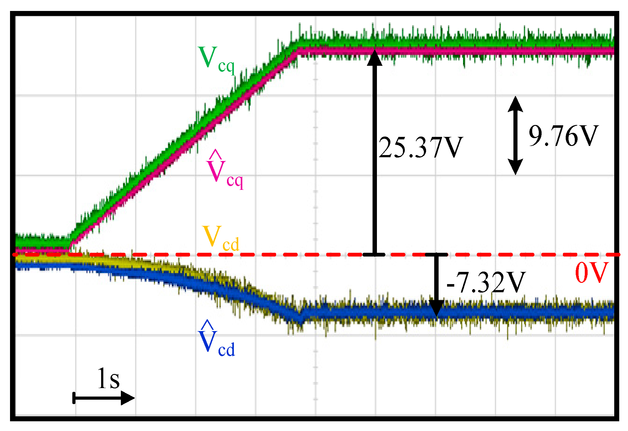
5.3. Capacitor Voltage Estimation

This section evaluates the capacitor voltage estimation using the proposed capacitor voltage observer in Figure 4. Figure 11 shows the comparison of the actual dq capacitor voltages VCdq and estimated capacitor voltages V ^ Cdq . Here, VCdq values were measured using external voltage sensors. In this test, the motor was accelerated from 6 krpm to 42 krpm within 4 s. The FOC drive was applied with external current sensors to clearly evaluate the estimation performance. In this test, the sensorless FOC was implemented where the rotor position was obtained from the EMF estimation. Because the EMF is insufficient at very low speed, the proposed FOC drive with an LC filter was implemented at 6 krpm with accurate EMF estimation. As seen in Figure 11, V ^ Cdq was close to VCdq n the range of 6~42 krpm under different voltage magnitudes. It is concluded that the proposed voltage observer can obtain actual capacitor voltages at different speeds and magnitudes using only the existing drive current sensors.

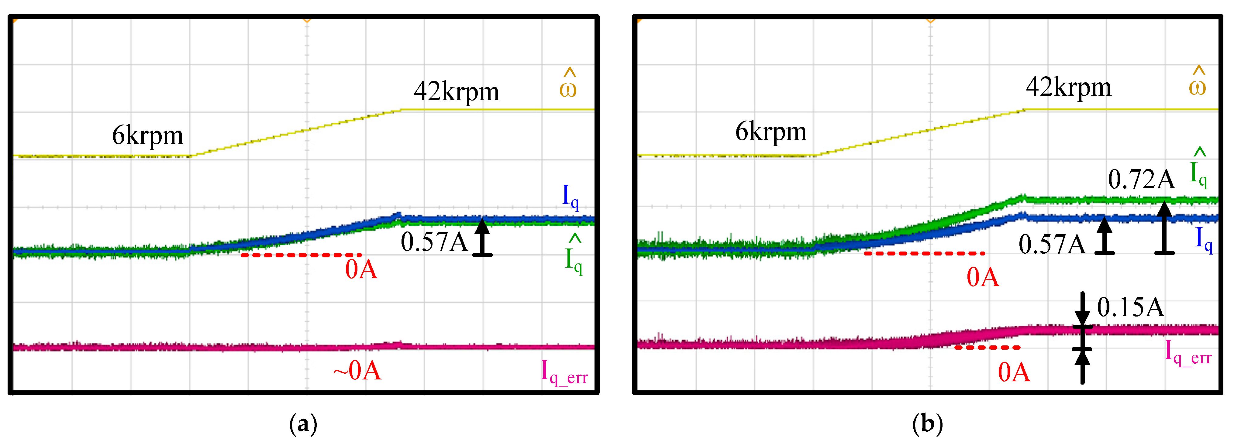
5.4. Motor Current Estimation

This section shows the machine current estimation using the proposed capacitor current observer in Figure 6. It is noted that both the machine current Idq and capacitor current ICdq can be obtained from this observer. In this context, only the motor I ^ dq estimation performance is evaluated for simplicity.
Figure 12 compares the actual machine Idq and estimated I ^ dq using the proposed current observer. The test condition was the same as Figure 11 in terms of the acceleration with the FOC drive. As shown in Figure 8, an external fan was coupled to the machine shaft to easily manipulate the torque load. This machine drive test setup was similar to [26]. In general, the torque load is a quadratic function dependent on the machine speed. At 6 krpm, as shown in Figure 12, relatively high current noises were observed. However, the current noises were negligible as the speed increased since the magnitude of noise remained the same irrespective of the speed.
More importantly, I ^ dq was close to Idq irrespective of the machine speed and current magnitude. As seen in Figure 12, q-axis current estimation error was around 2.56% at 6 krpm. This increased to 4.54% as the speed increased to 42 krpm. In contrast, the d-axis current estimation error was negligible for the speeds between 6 krpm and 42 krpm. As a result, the proposed current observer was also able to estimate I ^ dq accurately at different speeds once the current magnitude was higher than a certain value.
Figure 13 further illustrates the time-domain waveforms of machine AB-line voltage V ^ AB and machine A-phase current I ^ A at a low speed of 1 krpm (16.67 Hz) with respect to the externally measured VAB and IA. Both (a) a 25% load and (b) a 50% load were compared based on different fan load sizes. For the voltage estimation, V ^ AB was close to VAB at different loads. It is noted that the filter cutoff frequency was designed at 2.92 kHz. In this case, the PWM voltage could be removed in both VAB and V ^ AB , leading to nearly sinusoidal voltage waveforms. In contrast, for current estimation, a relatively low signal-to-noise ratio was observed in I ^ A . As mentioned in Equation (18), the machine current was estimated from voltage disturbances V ^ dis _ dq through the RLC circuit model. This voltage was relatively small at low speed, resulting in estimation noises. However, the magnitudes between I ^ A and IA were almost the same. It is concluded that the proposed machine current estimation can still be used for FOC current regulation.

5.5. Sensitivity Analysis of Filter State Estimation

This section further verifies the influence of filter parameter errors on the proposed observer-based estimation. As mentioned in Figure 5, the estimation of the filter output machine current I ^ dq requires a filter capacitor and inductance parameter. More importantly, these parameter errors can be reduced using the proposed observer with the closed-loop feedback regulation.
Figure 14 shows the time-domain waveforms of the measured speed, measured and estimated machine Iq and I ^ q and the estimation error I q     I ^ q . The test condition was the same as in Figure 11 and Figure 12 in terms of the FOC acceleration. In (a), a 50% capacitor parameter error was intentionally added in the proposed current observer. The current estimation error was negligible as the speed accelerated from 6 krpm to 42 krpm. Thus, the proposed current observer demonstrated negligible sensitivity under the filter capacitor variation. This test result is consistent with the analytical model in Figure 5c.
In contrast, in Figure 14b, the same 50% filter inductance error was included to evaluate the same I ^ q estimation performance. In contrast to the capacitor parameter, the estimation error increased as the speed increased. At 6 krpm, the current estimation error was negligible. However, this error increased to 26.3% as the speed increased to 42 krpm. This result was the same as the simulation in Figure 5a. Nevertheless, the filter inductance parameter should be known as it is selected by the drive designer.

5.6. FOC Performance Comparison

The machine speed closed-loop control for the drive with an LC filter is compared in this section. Figure 15 compares the current regulation using the feedback of (a) the inverter current ILdq in Figure 1, (b) the estimated machine current I ^ dq with direct estimation in Equation (14) and (c) the estimated machine current I ^ dq with proposed observer-based estimation in Figure 6. Due to the encoder installation issue on the test machine, the EMF-based position estimation was applied where the estimated capacitor voltage V ^ Cdq was used for the position estimation, as illustrated in Figure 2.
As shown in Figure 15a, if the inverter current ILdq was directly used for current regulation ignoring the resonant dynamics of the LC filter, the speed control ultimately failed when the speed reached 40 krpm (666.7 Hz frequency). The difference between ILdq and Idq at high speed was the primary issue. In contrast, in (b) when the directly estimated I ^ dq was used, the speed control was able to stably operate at the rated speed under fan load. However, current noises were observed. These current noises resulted in speed estimation noises with 5.5% error in the high-speed region. More importantly, in Figure 15c, better current regulation performance compared to (b) was achieved using the capacitor current observer for I ^ dq estimation. In particular, at a high-speed of 42 krpm, there was no evident noise in the speed estimation error. For both direct estimation and proposed dual-observer, there was a 5.5% error in speed estimation at 6 krpm due to the low noise-to-signal ratio of back-EMF voltage. Thus, the proposed dual-observer could accurately obtain V ^ Cdq and I ^ dq for the position sensorless FOC drives under the PWM drive with an LC filter.

6. Conclusions

This paper proposes a dual-observer to estimate the capacitor voltage/current and machine current for a sensorless FOC drive using the drive inside current sensors. The observer estimation performance considering the filter parameter sensitivity is fully investigated. Table 2 lists the performance comparison of the conventional model-based estimation and proposed dual-observer estimation. Compared to conventional model-based estimation, the proposed dual-observer demonstrates robust estimation performance under parameter errors. The capacitor parameter error results in a negligible influence on the proposed observer estimation. The filter inductance error only affects the capacitor current estimation at high speed. By using commercial PWM drives, the FOC can be applied to PM machines where an LC filter is added to reduce the PWM harmonics.

Author Contributions

Methodology, C.-M.L. and S.-C.Y.; software and hardware implementation, C.-M.L., Y.-J.L., J.-Y.C. and G.-R.C.; formal analysis, C.-M.L.; writing—original draft preparation, C.-M.L. and S.-C.Y.; writing—review and editing, Y.-J.L., G.-R.C. and S.-C.Y.; supervision, S.-C.Y.; All authors have read and agreed to the published version of the manuscript.

Funding

The authors gratefully acknowledge the financial and equipment support from the National Taiwan University, Taiwan, R.O.C. under Grant 09HT512031 and Ministry of Science and Technology (MOST), Taiwan, R.O.C. under Grant 109-2221-E-002-011.

Informed Consent Statement

Not applicable.

Data Availability Statement

Data sharing is not applicable to this article.

Conflicts of Interest

The authors declare no conflict of interest.

References

  1. Gamazo-Real, J.C.; Vazquez-Sanchez, E.; Gomez-Gil, J. Position and speed control of brushless DC motors using sensorless techniques and application trends. Sensors 2010, 10, 6901–6947. [Google Scholar] [CrossRef] [PubMed] [Green Version]
  2. Huh, N.; Park, H.S.; Lee, M.H.; Kim, J.M. Hybrid PWM Control for Regulating the High-Speed Operation of BLDC Motors and Expanding the Current Sensing Range of DC-link Single-Shunt. Energies 2019, 12, 4347. [Google Scholar] [CrossRef] [Green Version]
  3. Kim, H.J.; Park, H.S.; Kim, J.M. Expansion of Operating Speed Range of High-Speed BLDC Motor Using Hybrid PWM Switching Method Considering Dead Time. Energies 2020, 13, 5212. [Google Scholar] [CrossRef]
  4. Coballes-Pantoja, J.; Gomez-Fuentes, R.; Noriega, J.R.; Garcia-Delgado, L.A. Parallel Loop Control for Torque and Angular Velocity of BLDC Motors with DTC Commutation. Electronics 2020, 9, 279. [Google Scholar] [CrossRef] [Green Version]
  5. Yao, Y.; Peng, F.; Huang, Y. In Proceedings of the Position and Capacitor Voltage Sensorless Control of High-Speed Surface-Mounted PMSM Drive with Output Filter. In Proceedings of the 2018 IEEE Energy Conversion Congress and Exposition (ECCE), Portland, OR, USA, 23–27 September 2018; pp. 2374–2381. [Google Scholar]
  6. Sikora, A.; Wozniak, M. Impact of Current Pulsation on BLDC Motor Parameters. Sensors 2021, 21, 587. [Google Scholar] [CrossRef] [PubMed]
  7. Kojima, M.; Hirabayashi, K.; Kawabata, Y.; Ejiogu, E.C.; Kawabata, T. Novel vector control system using deadbeat-controlled PWM inverter with output LC filter. IEEE Trans. Ind. Appl. 2004, 40, 162–169. [Google Scholar] [CrossRef]
  8. Bahrani, B.; Rufer, A.; Kenzelmann, S.; Lopes, L.A.C. Vector Control of Single-Phase Voltage-Source Converters Based on Fictive-Axis Emulation. IEEE Trans. Ind. Appl. 2011, 47, 831–840. [Google Scholar] [CrossRef]
  9. Monfared, M.; Golestan, S.; Guerrero, J.M. Analysis, Design, and Experimental Verification of a Synchronous Reference Frame Voltage Control for Single-Phase Inverters. IEEE Trans. Ind. Electron. 2014, 61, 258–269. [Google Scholar] [CrossRef]
  10. Yen, S.H.; Tang, P.C.; Lin, Y.C.; Lin, C.Y. A Sensorless and Low-Gain Brushless DC Motor Controller Using a Simplified Dynamic Force Compensator for Robot Arm Application. Sensors 2019, 19, 3171. [Google Scholar] [CrossRef] [Green Version]
  11. He, J.; Li, Y.W. Generalized Closed-Loop Control Schemes with Embedded Virtual Impedances for Voltage Source Converters with LC or LCL Filters. IEEE Trans. Power Electron. 2012, 27, 1850–1861. [Google Scholar] [CrossRef]
  12. Wang, X.; Loh, P.C.; Blaabjerg, F. Stability Analysis and Controller Synthesis for Single-Loop Voltage-Controlled VSIs. IEEE Trans. Power Electron. 2017, 32, 7394–7404. [Google Scholar] [CrossRef] [Green Version]
  13. Li, W.; Ruan, X.; Pan, D.; Wang, X. Full-Feedforward Schemes of Grid Voltages for a Three-Phase LCL-Type Grid-Connected Inverter. IEEE Trans. Ind. Electron. 2013, 60, 2237–2250. [Google Scholar] [CrossRef]
  14. Hatua, K.; Jain, A.K.; Banerjee, D.; Ranganathan, V.T. Active Damping of Output LC Filter Resonance for Vector-Controlled VSI-Fed AC Motor Drives. IEEE Trans. Ind. Electron. 2012, 59, 334–342. [Google Scholar] [CrossRef]
  15. Kim, H.-S.; Jung, H.-S.; Sul, S.-K. Discrete-Time Voltage Controller for Voltage Source Converters with LC Filter Based on State-Space Models. IEEE Trans. Ind. Appl. 2019, 55, 529–540. [Google Scholar] [CrossRef]
  16. Vazquez, S.; Rodriguez, J.; Rivera, M.; Franquelo, L.G.; Norambuena, M. Model Predictive Control for Power Converters and Drives: Advances and Trends. IEEE Trans. Ind. Electron. 2017, 64, 935–947. [Google Scholar] [CrossRef] [Green Version]
  17. Salomaki, J.; Hinkkanen, M.; Luomi, J. Sensorless Control of Induction Motor Drives Equipped with Inverter Output Filter. IEEE Trans. Ind. Electron. 2006, 53, 1188–1197. [Google Scholar] [CrossRef]
  18. SalomÄki, J.; Hinkkanen, M.; Luomi, J. Influence of Inverter Output Filter on Maximum Torque and Speed of PMSM Drives. IEEE Trans. Ind. Appl. 2008, 44, 153–160. [Google Scholar] [CrossRef] [Green Version]
  19. Busada, C.A.; Jorge, S.G.; Solsona, J.A. Full-State Feedback Equivalent Controller for Active Damping in LCL-Filtered Grid-Connected Inverters Using a Reduced Number of Sensors. IEEE Trans. Ind. Electron. 2015, 62, 5993–6002. [Google Scholar] [CrossRef]
  20. Sapin, A.; Steimer, P.K.; Simond, J. Modeling, Simulation, and Test of a Three-Level Voltage-Source Inverter with Output LC Filter and Direct Torque Control. IEEE Trans. Ind. Appl. 2007, 43, 469–475. [Google Scholar] [CrossRef]
  21. Hsu, C.; Yang, S.; Chen, J. Implementation of Low Inductance Permanent Magnet Machine Drive with LC Filter for Field Oriented Control. In Proceedings of the 2019 IEEE Energy Conversion Congress and Exposition (ECCE), Baltimore, MD, USA, 29 September–3 October 2019; pp. 6140–6146. [Google Scholar]
  22. Parker, S.G.; McGrath, B.P.; Holmes, D.G. Regions of Active Damping Control for LCL Filters. IEEE Trans. Ind. Appl. 2014, 50, 424–432. [Google Scholar] [CrossRef]
  23. Wang, T.C.Y.; Zhihong, Y.; Gautam, S.; Xiaoming, Y. Output filter design for a grid-interconnected three-phase inverter. In Proceedings of the IEEE 34th Annual Conference on Power Electronics Specialist, PESC ‘03, Acapulco, Mexico, 15–19 June 2003; Volume 2, pp. 779–784. [Google Scholar]
  24. Ahmed, K.H.; Finney, S.J.; Williams, B.W. Passive Filter Design for Three-Phase Inverter Interfacing in Distributed Generation. In Proceedings of the 2007 Compatibility in Power Electronics, Gdansk, Poland, 29 May–1 June 2007; pp. 1–9. [Google Scholar]
  25. Sun, W.; Gao, J.; Liu, X.; Yu, Y.; Wang, G.; Xu, D. Inverter Nonlinear Error Compensation Using Feedback Gains and Self-Tuning Estimated Current Error in Adaptive Full-Order Observer. IEEE Trans. Ind. Appl. 2016, 52, 472–482. [Google Scholar] [CrossRef]
  26. Atlam, O.; Kolhe, M. Performance evaluation of directly photovoltaic powered DC PM (direct current permanent magnet) motor—Propeller thrust system. Energy 2013, 57, 692–698. [Google Scholar] [CrossRef]
Figure 1. Machine drive with output LC filter [21].
Sensors 21 03596 g001
Figure 2. Illustration of FOC machine drive with LC filter using proposed dual-observer for the filter voltage and current estimation.
Sensors 21 03596 g002
Figure 3. Estimation accuracy evaluation of V ^ Cdq between direct estimation in (4) and proposed observer in Equation (9): (a) R ^ f error on |VCd_err(jω)/ILd(jω)|, (b) L f ^ error on |VCd_err(jω)/ILd(jω)|, and (c) L ^ f error on |VCd_err(jω)/ILp(jω)|.
Sensors 21 03596 g003
Figure 4. Proposed first closed-loop observer in Figure 2 for capacitor voltage estimation (capacitor voltage observer).
Sensors 21 03596 g004
Figure 5. Estimation accuracy evaluation of I ^ Cdq between direct estimation in Equation (13) and proposed observer in Figure 6: (a) L ^ f error on |ICd_err(jω)/ILd(jω)|, (b) L ^ f error on |ICd_err(jω)/ILq(jω)|, and (c) C ^ p error on |ICd_err(jω)/ V d (jω)|.
Sensors 21 03596 g005
Figure 6. Proposed second observer in Figure 2 for capacitor current estimation and machine current estimation.
Sensors 21 03596 g006
Figure 7. Simplification of capacitor current observer in Figure 6.
Sensors 21 03596 g007
Figure 8. Test setup of PM motor drive with LC filter.
Sensors 21 03596 g008
Figure 9. Machine three-phase currents and the corresponding spectrum for the drive (a) without and (b) with LC filter (40 krpm and fan load).
Sensors 21 03596 g009
Figure 10. Experimental comparison of A-phase inverter output current ILA capacitor current ICA and machine actual current IA at (a) a low speed of 1 krpm and (b) a high speed of 40 krpm (FOC drive and fan load).
Sensors 21 03596 g010
Figure 11. Experiment of capacitor voltage estimation performance (acceleration from 6 krpm to 42 krpm within 4 s and fan load).
Sensors 21 03596 g011
Figure 12. Experiment of machine current estimation performance (acceleration from 6 krpm to 42 krpm within 4 s and fan load).
Sensors 21 03596 g012
Figure 13. Experiment of estimated filter output capacitor voltage and machine current at (a) 25% and (b) 50% load (1 krpm rotor speed).
Sensors 21 03596 g013
Figure 14. Sensitivity analysis of proposed observer-based current estimation under (a) filter capacitor error and (b) inductance error (6 krpm to 42 krpm and fan load).
Sensors 21 03596 g014
Figure 15. Comparison of current regulation using (a) inverter current ILdq, (b) estimated machine current I ^ dq with direct estimation in (14) and (c) estimated machine current I ^ dq with proposed observer-based estimation in Figure 6.
Sensors 21 03596 g015
Table 1. Test PM machine characteristics.
Test MachineValues
Rotor poles2-pole
Rated torque25 mNm
Rated current2 A
Rated speed42 krpm (700 Hz elec. frequency)
Phase resistance0.85 Ω
Phase inductance130 μH
DC bus voltage40 V
LC FilterValues
Inductance1 mH
Capacitor25.8 μF
Resonant frequency2.92 kHz
Table 2. Comparison between conventional model-based estimation and proposed dual-observer estimation.
Model-Based EstimationProposed Dual-Observer
Parameter sensitivityCapacitor and inductor sensitive (drive is unstable for experimental test)Capacitor (negligible error)
Inductor (negligible error at 6 krpm and 26.3% error at 42 krpm)
FOC speed control5.5% error between 6~42 krpm5.5% error at 6 krpm and negligible error at 42 krpm
Memory usage14.2 Kb18.5 Kb
Publisher’s Note: MDPI stays neutral with regard to jurisdictional claims in published maps and institutional affiliations.

