
Multisensorial Assessment of Laser Effects on Shellac Applied on Wall Paintings

 ,
, 
 ,
,
Abstract
1. Introduction
2. Materials and Methods
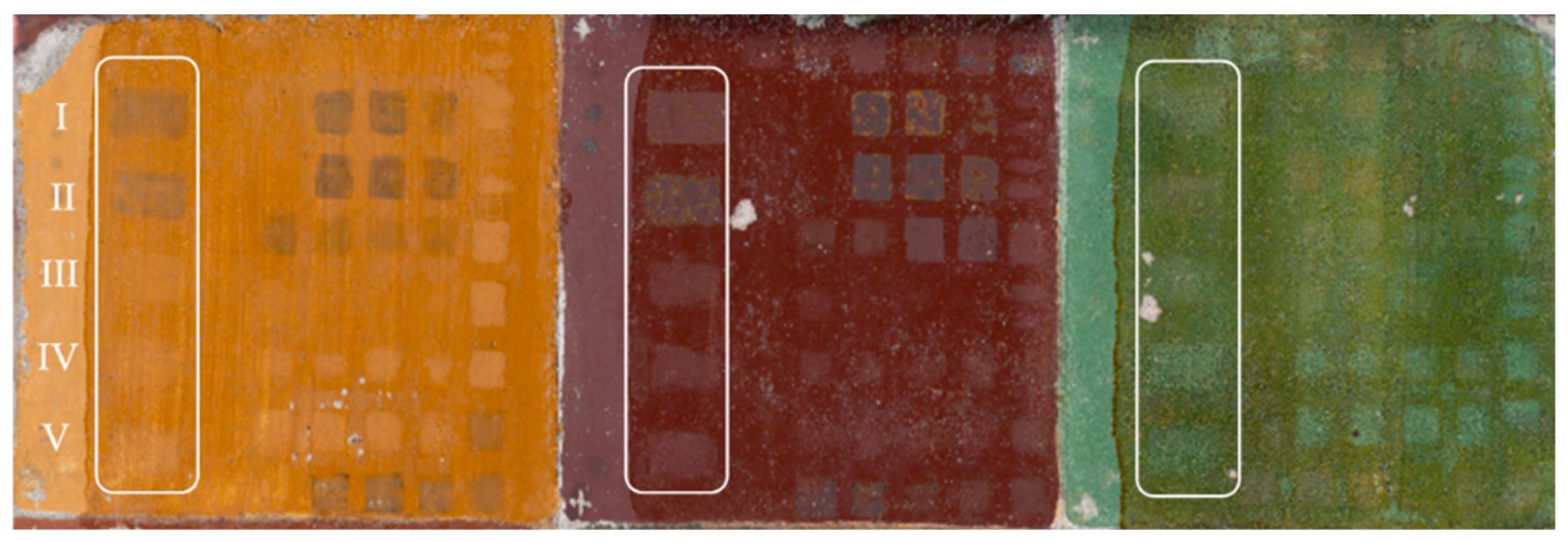
2.1. Samples
2.2. Laser Treatments
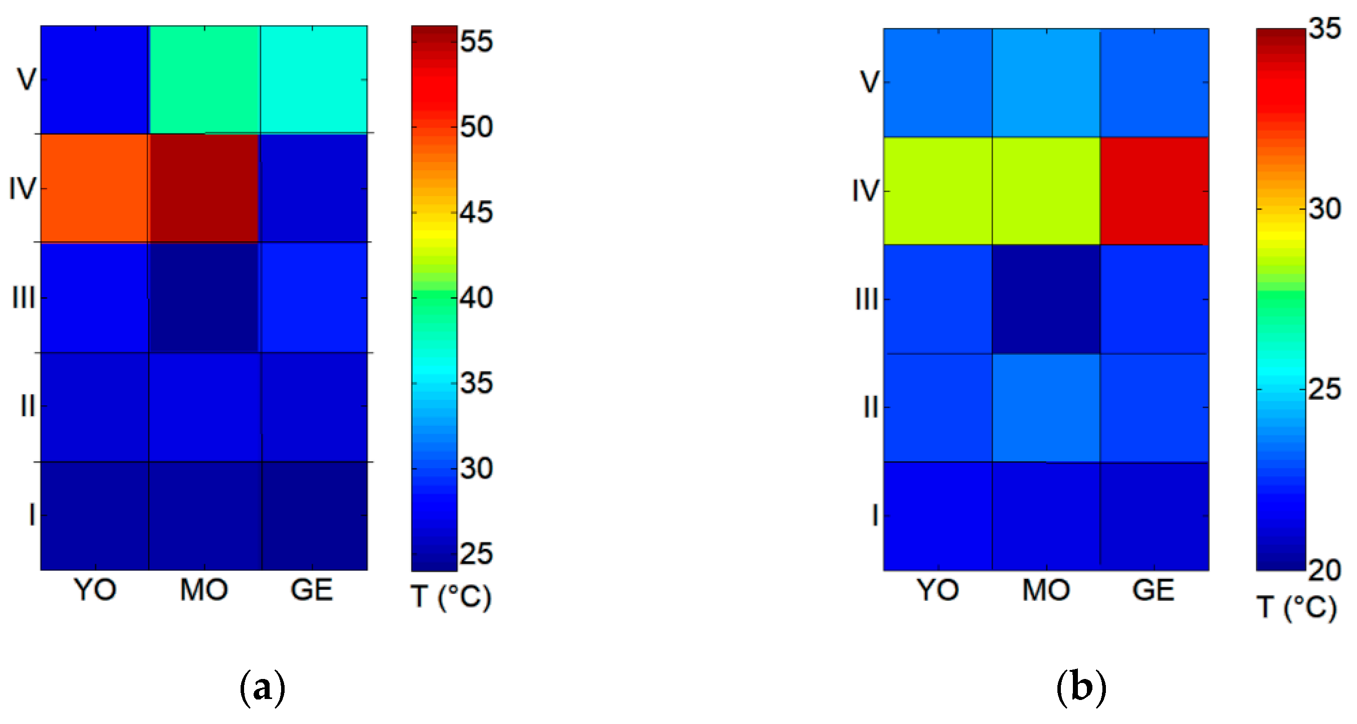
2.3. IR Thermography to Assess the Surface Temperature
2.4. UV-VIS-NIR Imaging and Color Measurements
2.5. OCT for Thickness and Morphologic Evaluation
3. Results
3.1. Real-Time Temperature Monitoring
3.2. UV-VIS Imaging and Colorimetric Characterization
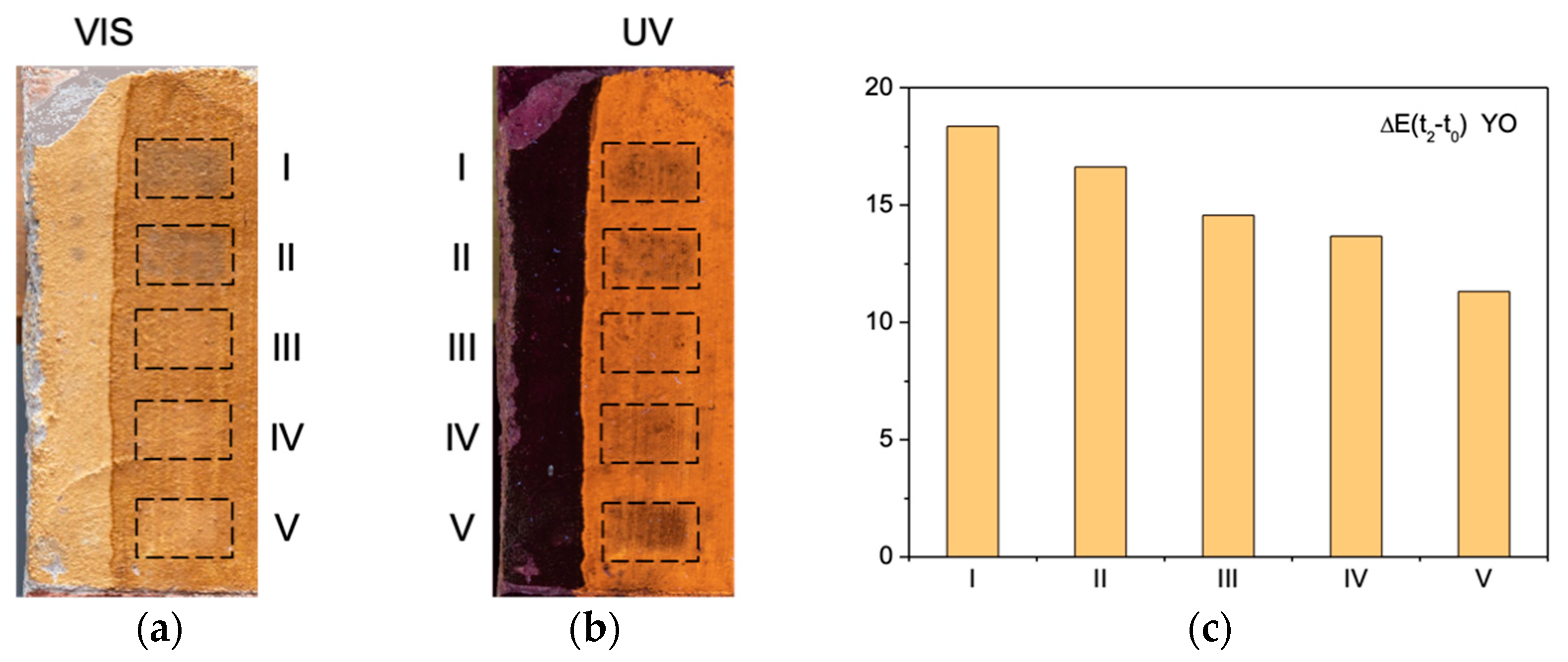
3.2.1. Yellow Ochre
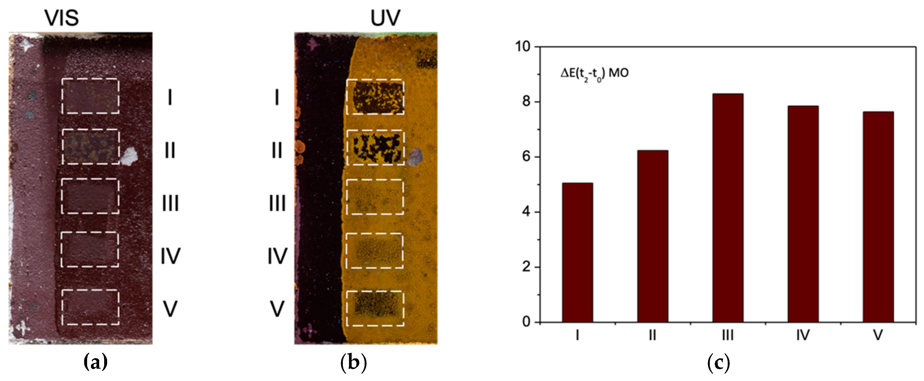
3.2.2. Morellone
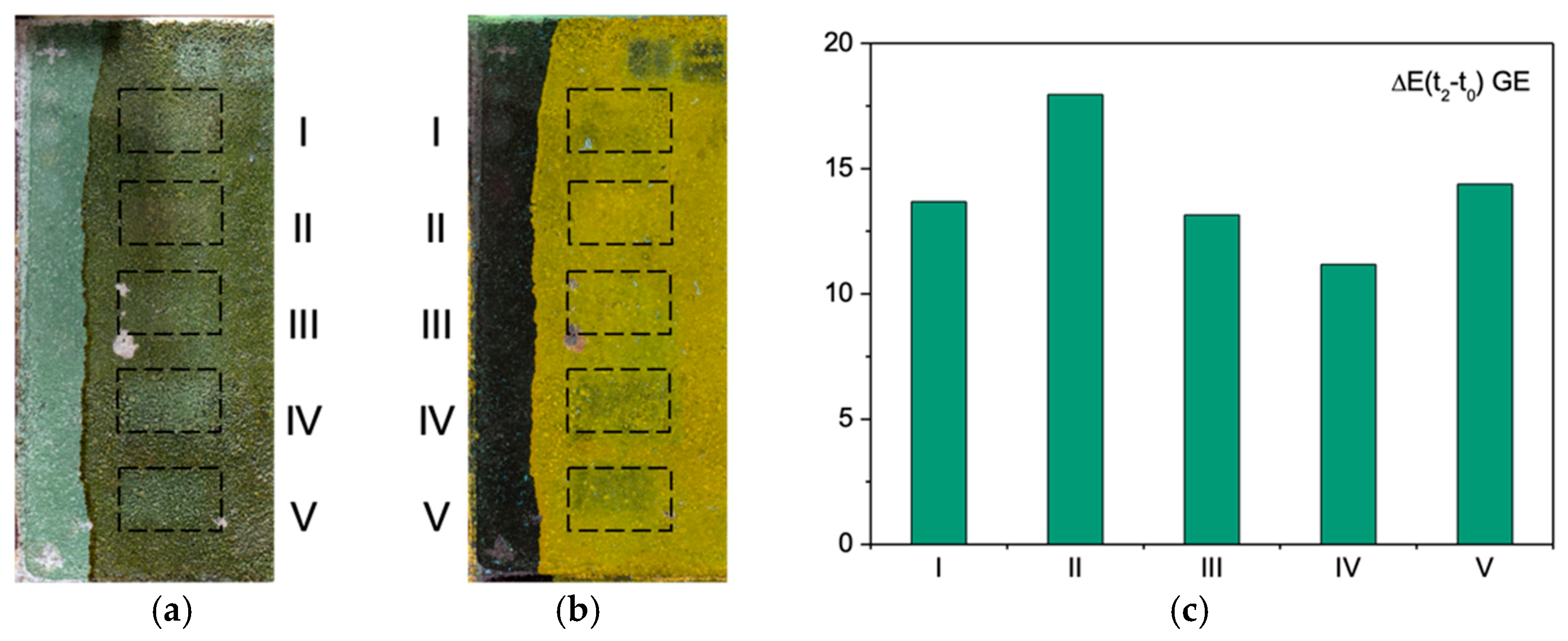
3.2.3. Green Earth
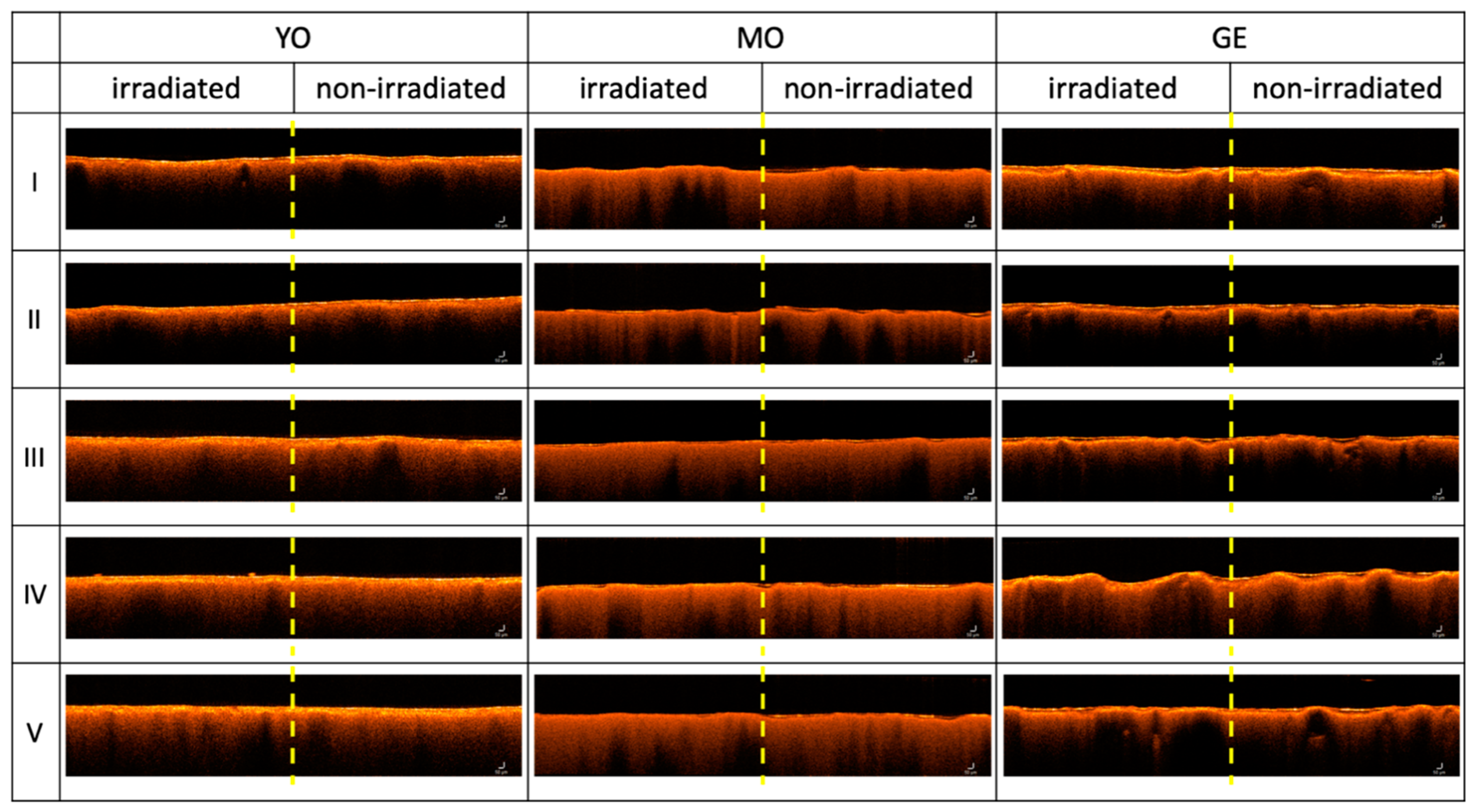
3.3. Thickness Evaluation of the Shellac Removal by OCT
4. Discussion
5. Conclusions
Author Contributions
Funding
Institutional Review Board Statement
Informed Consent Statement
Data Availability Statement
Acknowledgments
Conflicts of Interest
References
- Standard EN 17138:2019: Conservation of Cultural Heritage–Methods and Materials for Cleaning Porous Inorganic Materials; British Standards Institution (BSI): London, UK, 2019.
- Mora, P.; Mora, L.; Philippot, P. Conservation of Wall Paintings; Butterworths: London, UK, 1984. [Google Scholar]
- Brajer, I.; Shashoua, Y.; Taube, M.; Chelazzi, D.; Baglioni, M.; Baglioni, P. The removal of aged acrylic coatings from wall paintings using microemulsions. In Proceedings of the ICOM-CC 17th Triennial Conference Preprints, Melbourne, Australia, 15–19 September 2014. [Google Scholar]
- Salimbeni, R.; Pini, R.; Siano, S. Achievement of optimum laser cleaning in the restoration of artworks: Expected improvements by on-line optical diagnostics. Spectrochim. Acta B 2001, 56, 877–885. [Google Scholar] [CrossRef]
- Andreotti, A.; Bracco, P.; Colombini, M.P.; de Cruz, A.; Lanterna, G.; Nakahara, K.; Penaglia, F. Preliminary Results of the Er:YAG Laser Cleaning of Mural Paintings. In Lasers in the Conservation of Artworks; Springer: Berlin/Heidelberg, Germany, 2007; pp. 203–210. [Google Scholar]
- Andreotti, A.; Colombini, M.P.; Nevin, A.; Melessanaki, K.; Pouli, P.; Fotakis, C. Multianalytical Study of Laser Pulse Duration Effects in the IR Laser Cleaning of Wall Paintings from the Monumental Cemetery of Pisa. Laser Chem. 2007, 2006, 39046. [Google Scholar] [CrossRef][Green Version]
- Striova, J.; Castellucci, E.; Sansonetti, A.; Camaiti, M.; Matteini, M.; Decruz, A.; Andreotti, A.; Colombini, M.P. Free-running Er: YAG laser cleaning of mural painting specimens treated with linseed oil, ‘Beverone’and Paraloid B72. In Proceedings of the International Conference on Lasers in the Conservation of Artworks VIII, Sibiu, Romania, 21–25 September 2009; pp. 85–92. [Google Scholar]
- Siano, S.; Agresti, J.; Cacciari, I.; Ciofini, D.; Mascalchi, M.; Osticioli, I.; Mencaglia, A.A. Laser cleaning in conservation of stone, metal, and painted artifacts: State of the art and new insights on the use of the Nd:YAG lasers. Appl. Phys. A 2012, 106, 419–446. [Google Scholar] [CrossRef]
- Papadakis, V.; Loukaiti, A.; Pouli, P. A spectral imaging methodology for determining on-line the optimum cleaning level of stonework. J. Cult. Herit. 2010, 11, 325–328. [Google Scholar] [CrossRef]
- Striova, J.; Camaiti, M.; Castellucci, E.M.; Sansonetti, A. Chemical, Morphological and Chromatic Behavior of Mural Paintings under Er:YAG Laser Irradiation. Appl. Phys. A 2011, 104, 649–660. [Google Scholar] [CrossRef]
- Barbetti, I.; Felici, A.; Magrini, D.; Manganelli Del Fa, R.; Riminesi, C. Ultra Close-range Photogrammetry to Assess the Roughness of the Wall painting surfaces after Cleaning Treatments. Int. J. Conserv. Sci. 2013, 4, 525–534. [Google Scholar]
- Striova, J.; Salvadori, B.; Fontana, R.; Sansonetti, A.; Barucci, M.; Pampaloni, E.; Marconi, E.; Pezzati, L.; Colombini, M.P. Optical and spectroscopic tools for evaluating Er:YAG laser removal of shellac varnish. Stud. Conserv. 2015, 60, S91–S96. [Google Scholar]
- Fontana, R.; Dal Fovo, A.; Striova, J.; Pezzati, L.; Pampaloni, E.; Raffaelli, M.; Barucci, M. Application of non-invasive optical monitoring methodologies to follow and record painting cleaning processes. Appl. Phys. A 2015, 121, 957–966. [Google Scholar] [CrossRef]
- Striova, J.; Fontana, R.; Barucci, M.; Felici, A.; Marconi, E.; Pampaloni, E.; Raffaelli, M.; Riminesi, C. Optical devices provide unprecedented insights into the laser cleaning of calcium oxalate layers. Microchem. J. 2016, 124, 331–337. [Google Scholar] [CrossRef]
- Pouli, P.; Emmony, D.C.; Madden, C.E.; Sutherland, I. Studies towards a thorough understanding of the laser-induced discoloration mechanisms of medieval pigments. J. Cult. Herit. 2003, 4, 271–275. [Google Scholar] [CrossRef]
- Semerok, A.; Chaléard, C.; Detalle, V.; Lacour, J.-L.; Mauchien, P.; Meynadier, P.; Nouvellon, C.; Sallé, B.; Palianov, P.; Perdrix, M.; et al. Experimental investigations of laser ablation efficiency of pure metals with femto, pico and nanosecond pulses. Appl. Surf. Sci. 1999, 138–139, 311–314. [Google Scholar] [CrossRef]
- Siano, S.; Salimbeni, R. The Gate of Paradise: Physical optimization of the laser cleaning approach. Stud. Conserv. 2001, 46, 269–281. [Google Scholar]
- Bromblet, P.; Labouré, M.; Orial, G. Diversity of the cleaning procedures including laser for the restoration of carved portals in France over the last 10 years. J. Cult. Herit. 2003, 4, 17–26. [Google Scholar] [CrossRef]
- Fotakis, C.; Anglos, D.; Zafiropulos, V.; Georgiou, S.; Tornari, V. Principles and applications. In Lasers in the Preservation of Cultural Heritage; Brown, R.G.W., Pike, E.R., Eds.; Taylor and Francis: New York, NY, USA, 2006. [Google Scholar]
- Attrilla, D.C.; Daviesa, R.M.; Kingb, T.A.; Dickinsonb, M.R.; Blinkhorna, A.S. Thermal effects of the Er:YAG laser on a simulated dental pulp: A quantitative evaluation of the effects of a water spray. J. Dent. 2004, 32, 35–40. [Google Scholar] [CrossRef]
- Liua, Q.S.; Mahdavianb, S.M.; Aswinb, D.; Dingb, S. Experimental study of temperature and clamping force during Nd:YAG laser butt welding. Opt. Laser Technol. 2009, 41, 794–799. [Google Scholar] [CrossRef]
- De Cruz, A.; Andreotti, A.; Ceccarini, A.; Colombini, M.P. Laser cleaning of works of art: Evaluation of the thermal stress induced by Er:YAG laser. Appl. Phys. B 2014, 117, 533–541. [Google Scholar] [CrossRef]
- Osticioli, I.; Mencaglia, A.A.; Siano, S. Temperature-controlled portable Raman spectroscopy of photothermally sensitive pigments. Sens. Actuators B 2017, 238, 772–778. [Google Scholar] [CrossRef]
- Das, A.K.; Teplitsky, S.; Humphreys, M.R. Holmium laser enucleation of the prostate (HoLEP): A review and update. Can. J. Urol. 2019, 26, 13–19. [Google Scholar]
- Gao, B.; Bobrowski, A.; Lee, J.A. scoping review of the clinical efficacy and safety of the novel thulium fiber laser: The rising start of laser lithotripsy. Can. Urol. Assoc. J. 2021, 15, 56–66. [Google Scholar] [CrossRef]
- Becker, B.; Gross, A.J.; Netsch, C. Ho:YAG laser lithotripsy: Recent innovations. Curr. Opin. Urol. 2019, 29, 103–107. [Google Scholar] [CrossRef]
- Georgiou, S.; Zafiropulos, V.; Anglos, D.; Tornari, V.; Fotakis, C. Excimer laser restoration of painted artworks: Procedures, mechanisms and effects. Appl. Surf. Sci. 1998, 127–129, 738–745. [Google Scholar] [CrossRef]
- Oujja, M.; Pouli, P.; Fotakis, C.; Domingo, C.; Castillejo, M. Analytical Spectroscopic Investigation of Wavelength and Pulse Duration Effects on Laser-Induced Changes of Egg-Yolk-Based Tempera Paints. Appl. Spectrosc. 2010, 64, 528–536. [Google Scholar] [CrossRef] [PubMed]
- Pouli, P.; Paun, I.-A.; Bounos, G.; Georgiou, S.; Fotakis, C. The potential of UV femtosecond laser ablation for varnish removal in the restoration of painted works of art. Appl. Surf. Sci. 2008, 254, 6875–6879. [Google Scholar] [CrossRef]
- Oujja, M.; Sanz, M.; Rebollar, E.; Marco, J.F.; Castillejo, M.; Pouli, P.; Kogou, S.; Fotakis, C. Wavelength and pulse duration effects on laser induced changes on raw pigments used in paintings. Spectrochim. Acta A. 2013, 102, 7–14. [Google Scholar] [CrossRef]
- Striova, J.; Ruberto, C.; Barucci, M.; Blazek, J.; Kunzelman, D.; Dal Fovo, A.; Pampaloni, E.; Fontana, R. Spectral imaging and archival data in analysing Madonna of the rabbit paintings by Manet and Titian. Angew. Chem. Int. Ed. 2018, 57, 7408–7412. [Google Scholar] [CrossRef] [PubMed]
- ISO/CIE. Colorimetry—Part 3: CIE tristimulus values, 11664-3, The International Organization for Standardization; ISO: Geneva, Switzerland, 2019. [Google Scholar]
- Bhattacharya, G.N. A note on refractive index of shellac. Indian J. Phys. 1940, 14, 237–246. [Google Scholar]
- The Conservation & Art Materials Encyclopedia. Available online: http://cameo.mfa.org/wiki/Shellac (accessed on 8 February 2021).
- Siano, S. Principles of laser cleaning in conservation. In Handbook on the Use of Lasers in Conservation and Conservation Science; Schreiner, M., Strlič, M., Salimbeni, R., Eds.; COST Office: Brussels, Belgium, 2008. [Google Scholar]
- Giachet, M.T.; Schröter, J.; Brambilla, L. Characterization and Identification of Varnishes on Copper Alloys by Means of UV Imaging and FTIR. Coatings 2021, 11, 298. [Google Scholar] [CrossRef]
- Coccato, A.; Moens, L.; Vandenabeele, P. On the stability of mediaeval inorganic pigments: A literature review of the effect of climate, material selection, biological activity, analysis and conservation treatments. Herit. Sci. 2017, 5, 12. [Google Scholar] [CrossRef]
- Grissom, C. Green Earth in Artist’s Pigments: A Handbook of Their History and Characteristics; Feller, R., Ed.; National Gallery of Art, Washington Archetype Publications: London, UK, 1986; Volume 1. [Google Scholar]


| Pigment Acronym | Pigment Type |
|---|---|
| YO | Yellow Ochre |
| MO | Morellone |
| GE | Green Earth |
| Treatment No. | Laser Source | Wave-Length λ [nm] | Pulse Width τ | Energy E [mJ] | Fluence F [J/cm2] | Frequency f [Hz] |
|---|---|---|---|---|---|---|
| I | Nd:YAG QS | 1064 | 15 ns | 60 | 1.2 | 5 |
| II | Nd:YAG LQS | 1064 | 100 ns | 150 | 3.1 | 5 |
| III | Nd:YAG SFR | 1064 | 5 μs | 100 | 2.0 | 5 |
| IV | Ho:YAG Ablation (short) | 2100 | 95 μs | 500 | 10.2 | 10 |
| V | Er:YAG Long | 2940 | 500 μs | 150 | 3.1 | 10 |
| Surface | L* | std | a* | std | b* | std | ΔL* | Δa* | Δb* |
|---|---|---|---|---|---|---|---|---|---|
| t0 | 69.0 | 0.0 | 10.7 | 0.6 | 39.3 | 2.1 | |||
| t1 | 54.0 | 1.7 | 18.7 | 0.6 | 51.3 | 1.2 | −15.0 | 8.0 | 12.0 |
| t2 I | 51.0 | 1.0 | 12.7 | 0.6 | 36.3 | 1.5 | −18.0 | 2.0 | −3.0 |
| t2 II | 53.0 | 1.0 | 13.3 | 0.6 | 35.7 | 1.2 | −16.0 | 2.7 | −3.7 |
| t2 III | 58.0 | 0.0 | 17.5 | 0.6 | 46.0 | 0.6 | −11.0 | 6.8 | 6.7 |
| t2 IV | 58.7 | 0.6 | 17.0 | 0.0 | 45.7 | 0.6 | −10.3 | 6.3 | 6.3 |
| t2 V | 60.0 | 1.0 | 16.0 | 0.0 | 43.7 | 1.2 | −9.0 | 5.3 | 4.3 |
| Surface | L* | std | a* | std | b* | std | ΔL* | Δa* | Δb* |
|---|---|---|---|---|---|---|---|---|---|
| t0 | 36.3 | 0.6 | 14.3 | 0.6 | 5.3 | 0.6 | |||
| t1 | 22.3 | 0.6 | 21.3 | 0.6 | 17.0 | 1.0 | −14.0 | 7.0 | 11.7 |
| t2 I | 33.0 | 1.0 | 13.3 | 0.6 | 9.0 | 1.7 | −3.3 | −1.0 | 3.7 |
| t2 II | 33.3 | 0.6 | 10.0 | 0.0 | 8.7 | 1.2 | −3.0 | −4.3 | 3.3 |
| t2 III | 29.5 | 0.6 | 16.5 | 0.6 | 9.5 | 0.6 | −6.8 | 2.2 | 4.2 |
| t2 IV | 30.0 | 0.0 | 16.7 | 0.6 | 9.3 | 0.6 | −6.3 | 2.3 | 4.0 |
| t2 V | 30.0 | 1.0 | 17.0 | 0.0 | 8.7 | 1.2 | −6.3 | 2.7 | 3.3 |
| Surface | L* | std | a* | std | b* | std | ΔL* | Δa* | Δb* |
|---|---|---|---|---|---|---|---|---|---|
| t0 | 55.7 | 0.6 | −17.0 | 1.0 | 13.0 | 0.0 | |||
| t1 | 42.7 | 4.0 | −12.0 | 0.0 | 28.0 | 2.6 | −13.0 | 5.0 | 15.0 |
| t2 I | 46.0 | 1.7 | −10.0 | 1.0 | 19.7 | 1.5 | −9.7 | 7.0 | 6.7 |
| t2 II | 42.3 | 0.6 | −8.7 | 1.2 | 21.7 | 1.5 | −13.3 | 8.3 | 8.7 |
| t2 III | 46.0 | 1.2 | −11.5 | 0.6 | 20.0 | 0.6 | −9.7 | 5.5 | 7.0 |
| t2 IV | 46.3 | 1.2 | −12.3 | 0.6 | 17.0 | 0.0 | −9.3 | 4.7 | 4.0 |
| t2 V | 42.7 | 0.6 | −12.7 | 0.6 | 17.3 | 0.6 | −13.0 | 4.3 | 4.3 |
| Sample | YO | MO | GE | ||||||
|---|---|---|---|---|---|---|---|---|---|
| Thickness [µ] | dmax–dmin | dr | std | dmax–dmin | dr | std | dmax–dmin | dr | std |
| Non-irradiated | 16–7 | 11 | 4 | 21–7 | 12 | 5 | 23–7 | 15 | 5 |
| I | 16–5 | 7 | 3 | n.d. | n.d. | n.d. | 23–7 | 14 | 6 |
| II | 9–2 | 6 | 2 | n.d. | n.d. | n.d. | 22–9 | 14 | 6 |
| III | 12–5 | 7 | 3 | 12–7 | 10 | 2 | 21–7 | 14 | 4 |
| IV | 12–7 | 9 | 2 | 16–5 | 11 | 3 | 12–5 | 8 | 2 |
| V | n.d. | n.d. | n.d. | 6–4 | 6 | 2 | 16–5 | 11 | 4 |
| Treatment | YO | MO | GE |
|---|---|---|---|
| t1−t0 | 20.8 | 19.5 | 20.5 |
| I | 18.4 | 5.1 | 13.7 |
| II | 16.6 | 6.2 | 18.0 |
| III | 14.6 | 8.3 | 13.1 |
| IV | 13.7 | 7.8 | 11.2 |
| V | 11.3 | 7.6 | 13.8 |
| Treatment | YO | MO | GE |
| I | Thinning Surface darkening | In-depth ablation Surface darkening | No evident cleaning No substrate modifications |
| II | Thinning Surface darkening | Delamination/Surface darkening | No evident cleaning No substrate modifications |
| III | Thinning No substrate modifications | Thinning No substrate modifications | No evident cleaning No substrate modifications |
| IV | Thinning No substrate modifications | Thinning No substrate modifications | Thinning No substrate modifications |
| V | Thinning No substrate modifications | Thinning No substrate modifications | Thinning No substrate modifications |
Publisher’s Note: MDPI stays neutral with regard to jurisdictional claims in published maps and institutional affiliations. |
© 2021 by the authors. Licensee MDPI, Basel, Switzerland. This article is an open access article distributed under the terms and conditions of the Creative Commons Attribution (CC BY) license (https://creativecommons.org/licenses/by/4.0/).
Share and Cite
Striova, J.; Fontana, R.; Barbetti, I.; Pezzati, L.; Fedele, A.; Riminesi, C. Multisensorial Assessment of Laser Effects on Shellac Applied on Wall Paintings. Sensors 2021, 21, 3354. https://doi.org/10.3390/s21103354
Striova J, Fontana R, Barbetti I, Pezzati L, Fedele A, Riminesi C. Multisensorial Assessment of Laser Effects on Shellac Applied on Wall Paintings. Sensors. 2021; 21(10):3354. https://doi.org/10.3390/s21103354
Chicago/Turabian StyleStriova, Jana, Raffaella Fontana, Ilaria Barbetti, Luca Pezzati, Annamaria Fedele, and Cristiano Riminesi. 2021. "Multisensorial Assessment of Laser Effects on Shellac Applied on Wall Paintings" Sensors 21, no. 10: 3354. https://doi.org/10.3390/s21103354
APA StyleStriova, J., Fontana, R., Barbetti, I., Pezzati, L., Fedele, A., & Riminesi, C. (2021). Multisensorial Assessment of Laser Effects on Shellac Applied on Wall Paintings. Sensors, 21(10), 3354. https://doi.org/10.3390/s21103354