Dynamic Frame Update Policy for UHF RFID Sensor Tag Collisions


Abstract
:
1. Introduction
Novel Contributions over Prior Work
- An analysis and classification of the state-of-the-art DFSA tag anti-collision protocols according to their frame update policy.
- A novel fast frame update policy for DFSA protocols. This policy first applies fuzzy logic to select the value of the slot where the frame size is updated. It then calculates the frame size as a function of the estimated number of tags inside the reader interrogation zone and the duration of the different time slots of the RFID platform.
- We introduce the anti-collision Fuzzy Frame Slotted Aloha (FFSA) protocol, which applies the previous policy to lower the average time to read a sensor data packet from one tag compared with existing recent strategies.
2. Analysis of Frame Update Policy of Dfsa Protocols
2.1. Frame Size Calculation
- Parameter Q, f(Q): the frame size can be adjusted by controlling the number and types of the slots in each frame with the parameter Q, so that Q increases when collisions are detected and decreases with increasing number of idle slots. Several approaches in the literature update L by adjusting Q [1,7,14,15,16,17].
- Tag set size estimation: several works in the literature have addressed the tag estimation task to provide an optimal frame size according to the estimated number of tags. It is known that a DFSA protocol reaches its maximum slot efficiency, which is defined as the ratio between the number of tags and the total number of slots required to identify them, when the frame size is equal to the number of tags. Therefore, to maximise this metric, the reader should set the frame size equal to the estimated number of tags. However, this condition of setting L = is only satisfied if the reader assumes that the three types of slots have equal duration. However, the standard EPC C1G2 determines that each time slot has a different duration. Consequently, some approaches set the frame size according to but assume unequal processing duration for each type of slot (single, collision, idle) [12,18].Once the tag set size has been estimated, the next step is to calculate L according to . Two main strategies to set L as a function of can be found in the literature, which is presented next.
2.2. Frame Size Examination
2.3. Frame Break Condition
- L fits n from an LUT, LUT(): some algorithms define an LUT based on and L [8,13] to check the appropriateness of L. First, the reader searches in the LUT for the corresponding value of L for the previously obtained . Then, if this new value differs from the current one, a new frame is started. Otherwise, the reader proceeds to the next slot of the current frame.
- Higher expected number of successful slots, : the authors in [10] define a policy to break the current frame and start a new one if the expected number of successful slots in the rest of the current frame is less than that expected in the new frame . In other words, a new frame is started if > .
- Lower Identification Time, (lower ): the authors in [16] present a frame cancellation strategy to minimise the total expected time to identify a tag set.
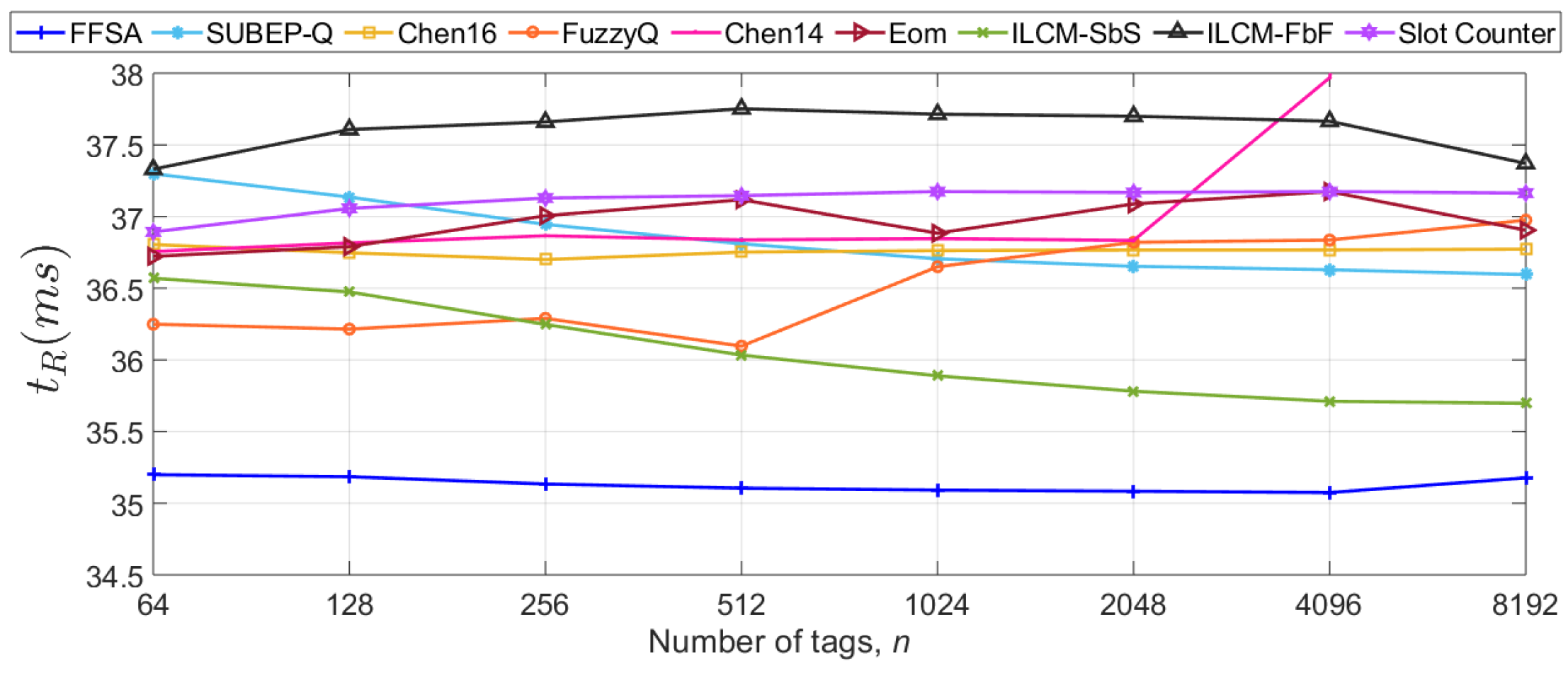
- Lower sensor read time, (lower ): this work presents a strategy where a new frame is started if the expected average time for reading one sensor packet in the new frame is lower than the one in the current frame.
- End of Frame, (EoF): a new frame is started when the current frame has finished. This strategy is intrinsic to a DFSA-based anti-collision protocol and it is applied in all the protocols analysed in the present paper.
3. Related Work: Classification of Dfsa Protocols
4. The Proposed Frame Update Policy
4.1. Frame Size Calculation to Minimise
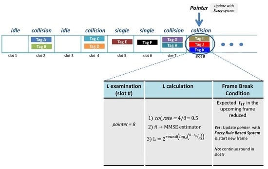
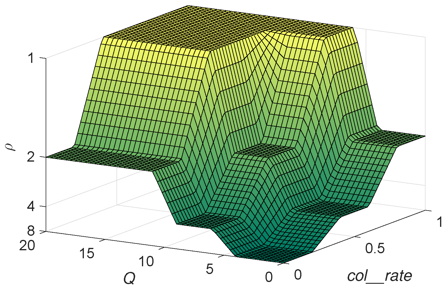
4.2. Frame Size Examination: Pbp
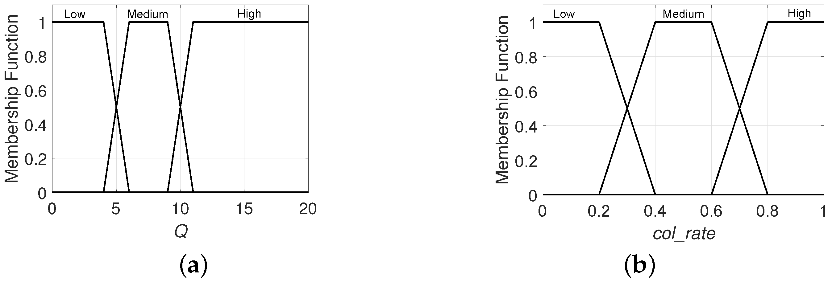
- Q: codifies the current value of this parameter which determines L, where and .
- : codifies the tag collision rate up to the current slot. This is defined by , and .
4.3. Frame Break Condition: Lower
4.4. The Proposed Fuzzy Frame Slotted Aloha Protocol
| Algorithm 1: Pseudocode of Fuzzy Frame Slotted Aloha (FFSA) protocol, reader operation. |
|
5. Performance Evaluation
- First slot of the inventory round: = .
- First slot of the frame: = .
- None of the above: = .
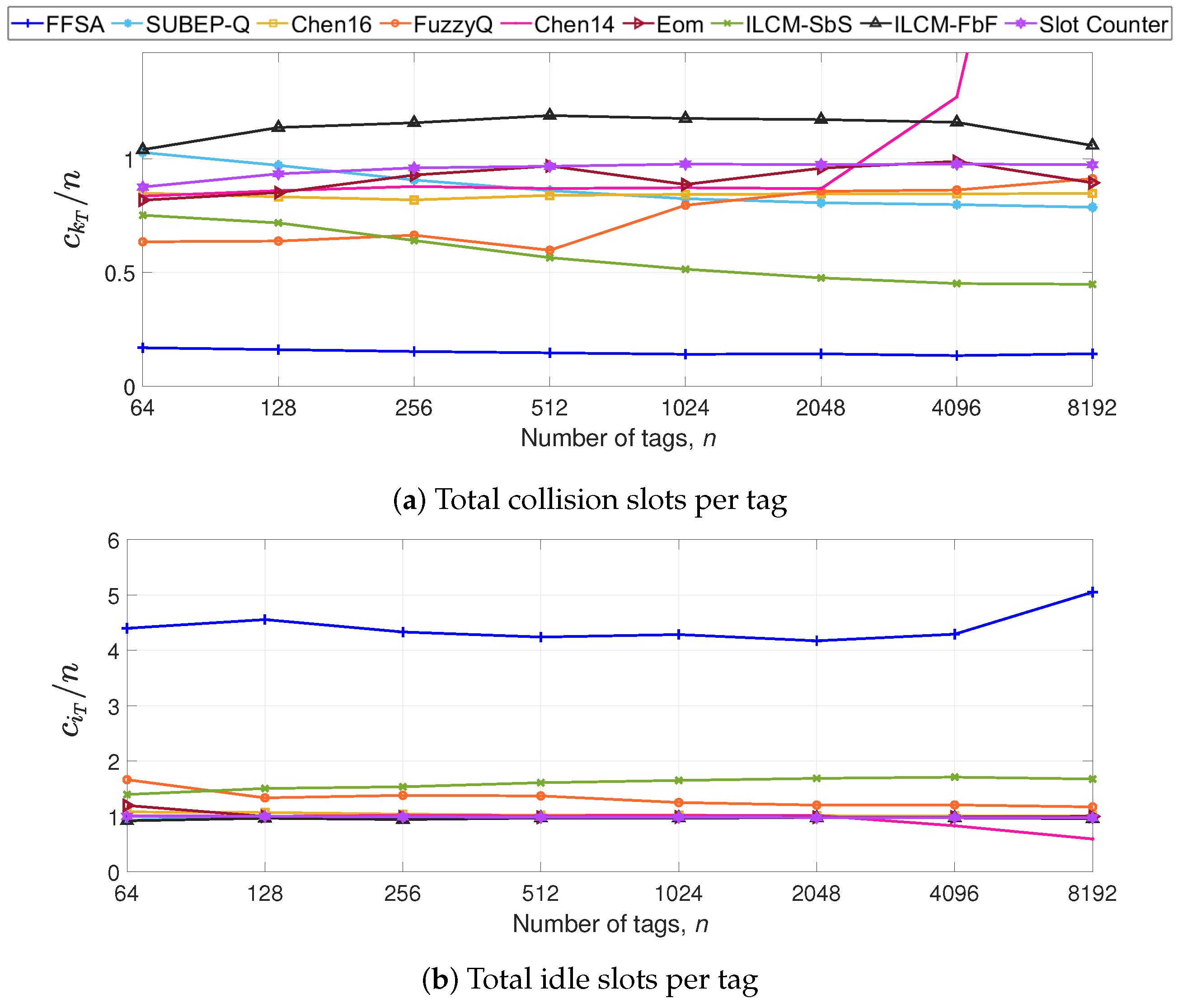
5.1. Impact of the Number of Tags in S1
5.2. Impact of the Tag Backscatter Link Frequency in S2
5.3. Discussion
5.4. Identified Limitations
6. Conclusions
Author Contributions
Funding
Conflicts of Interest
References
- Radio Frequency Identity Protocols Class-1 Generation-2 UHF RFID Protocol for Communications at 860 MHz–960 MHz; Release 2.1; EPCglobal Inc.: Brussels, Belgium, 2018.
- Liu, X.; Cao, J.; Yang, Y.; Qu, W.; Zhao, X.; Li, K.; Yao, D. Fast RFID sensory data collection: Trade-off between computation and communication costs. IEEE/ACM Trans. Netw. 2019, 27, 1179–1191. [Google Scholar] [CrossRef]
- Qiao, Y.; Chen, S.; Li, T.; Chen, S. Tag-ordering polling protocols in RFID systems. IEEE/ACM Trans. Netw. 2016, 24, 1548–1561. [Google Scholar] [CrossRef]
- Chen, S.; Zhang, M.; Xiao, B. Efficient information collection protocols for sensor-augmented RFID networks. In Proceedings of the 2011 Proceedings IEEE INFOCOM, Shanghai, China, 10–15 April 2011; pp. 3101–3109. [Google Scholar]
- Muhammad, S.; Liu, A.X. Expecting the unexpected: fast and reliable detection of missing RFID tags in the wild. In Proceedings of the 2015 IEEE Conference on Computer Communications (INFOCOM), Kowloon, Hong Kong, China, 26 April–1 May 2015. [Google Scholar]
- Farsens, EVAL01-Kineo-RM. 2019. Available online: http://www.farsens.com/wp-content/uploads/2018/07/DS-EVAL01-KINEO-RM-V05.pdf (accessed on 10 March 2020).
- Arjona, L.; Landaluce, H.; Perallos, A.; Onieva, E. Fast fuzzy anti-collision protocol for the RFID standard EPC Gen-2. Electron. Lett. 2016, 52, 663–665. [Google Scholar] [CrossRef]
- Chen, W.-T. A fast anticollision algorithm for the EPCglobal UHF class-1 Generation-2 RFID standard. IEEE Commun. Lett. 2014, 18, 1519–1522. [Google Scholar] [CrossRef]
- Eom, J.-B.; Lee, T.-J. Accurate tag estimation for dynamic framed-slotted ALOHA in RFID systems. IEEE Commun. Lett. 2010, 14, 60–62. [Google Scholar] [CrossRef]
- Solic, P.; Radic, J.; Rozic, N. Early frame break policy for ALOHA-based RFID systems. IEEE Trans. Autom. Sci. Eng. 2016, 13, 876–881. [Google Scholar] [CrossRef]
- Solic, P.; Radic, J.; Rozic, N. Energy efficient tag estimation method for ALOHA-based RFID systems. IEEE Sens. J. 2014, 14, 3637–3647. [Google Scholar] [CrossRef]
- Chen, W.T. Optimal frame length analysis and an efficient anti-collision algorithm with early adjustment of frame length for RFID systems. IEEE Trans. Veh. Technol. 2016, 65, 3342–3348. [Google Scholar] [CrossRef]
- Zhang, G.; Tao, S.; Cai, Q.; Gao, W.; Jia, J.; Wen, J. A fast and universal RFID tag anti-collision algorithm for the Internet of Things. IEEE Access 2019, 7, 92365–92377. [Google Scholar] [CrossRef]
- Lee, D.; Kim, K.; Lee, W. Q+-algorithm: An enhanced RFID tag collision arbitration algorithm. In Proceedings of the 4th International Conference on Ubiquitous Intelligence and Computing, Hong Kong, China, 11–13 July 2007. [Google Scholar]
- Daneshmand, M.; Wang, C.; Sohraby, K. A new slot-count selection algorithm for RFID protocol. In Proceedings of the Second International Conference on Communications and Networking in China, Shanghai, China, 22–24 August 2007; pp. 926–930. [Google Scholar]
- Zhu, L.; Yum, T.-S. The optimal reading strategy for EPC Gen-2 RFID anti-collision systems. IEEE Trans. Commun. 2010, 58, 2725–2733. [Google Scholar] [CrossRef]
- Teng, J.; Xuan, X.; Bai, Y. A fast Q algorithm based on EPC Generation-2 RFID protocol. In Proceedings of the 6th International Conference on Wireless Communications Networking and Mobile Computing, Chengdu, China, 23–25 September 2010; pp. 1–4. [Google Scholar]
- Porta, T.F.L.; Maselli, G.; Petrioli, C. Anticollision protocols for single-reader RFID systems: Temporal analysis and optimization. IEEE Trans. Mob. Comput. 2011, 10, 267–279. [Google Scholar] [CrossRef]
- Floerkemeier, C.; Wille, M. Comparison of transmission schemes for framed ALOHA based RFID protocols. In Proceedings of the International Symposium on Applications and the Internet Workshops, Phoenix, AZ, USA, 23–27 January 2006; pp. 4–97. [Google Scholar]
- Schoute, F. Dynamic frame length ALOHA. IEEE Trans. Commun. 1983, 31, 565–568. [Google Scholar] [CrossRef]
- Cha, J.-R.; Kim, J.-H. Dynamic framed slotted ALOHA algorithms using fast tag estimation method for RFID system. In Proceedings of the 3rd IEEE Consumer Communications and Networking Conference, Las Vegas, NV, USA, 8–10 January 2006; Volume 2, pp. 768–772. [Google Scholar]
- Chen, W.-T.; Lin, G. An efficient anti-collision method for RFID System. IEICE Trans. Commun. 2006, E89, 3386–3392. [Google Scholar] [CrossRef]
- Chen, W.-T. An efficient scheme for multiple access in a RFID system. In Proceedings of the 2006 International Conference on Wireless Networks, Sendai, Japan, 16–19 January 2006. [Google Scholar]
- Chen, W.-T. An accurate tag estimate method for improving the performance of an RFID anticollision algorithm based on dynamic frame length ALOHA. IEEE Trans. Autom. Sci. Eng. 2009, 6, 9–15. [Google Scholar] [CrossRef]
- Joe, I.; Lee, J. A novel anti-collision algorithm with optimal frame size for RFID system. In Proceedings of the 5th ACIS International Conference on Software Engineering Research, Management Applications, Busan, Korea, 20–22 August 2007; pp. 424–428. [Google Scholar]
- Vogt, H. Efficient object identification with passive RFID tags. In Pervasive Computing; Mattern, F., Naghshineh, M., Eds.; Volume 2414 of Lecture Notes in Computer Science; Springer: Berlin, Germany, 2002; pp. 98–113. [Google Scholar]
- Wang, B.S.; Zhang, Q.S.; Yang, D.K.; Di, J.S. Transmission control solutions using interval estimation method for EPC C1G2 RFID tag identification. In Proceedings of the International Conference on Wireless Communications, Networking and Mobile Computing, Dalian, China, 21–25 September 2007; pp. 2105–2108. [Google Scholar]
- Knerr, B.; Holzer, M.; Angerer, C. Slot-by-slot minimum squared error estimator for tags populations in FSA protocols. In Proceedings of the 2nd International EURASIP Workshop on RFID, Budapest, Hungary, 7–8 July 2008; pp. 1–13. [Google Scholar]
- Takagi, T.; Sugeno, M. Fuzzy identification of systems and its applications to modeling and control. IEEE Trans. Syst. Man Cybern. 1985, SMC-15, 116–132. [Google Scholar] [CrossRef]
- Wu, H.; Zeng, Y. Passive RFID tag anticollision algorithm for capture effect. IEEE Sens. J. 2015, 15, 218–226. [Google Scholar]


| Operation | |
|---|---|
| L calculation | f(Q) |
| f() | |
| LUT() | |
| L examination | FbF |
| SbS | |
| PbP | |
| Frame break condition | Different L |
| LUT() | |
| > | |
| Lower | |
| Lower | |
| EoF |
| L Calculation | L Exam | Frame Break Condition | ||||
|---|---|---|---|---|---|---|
| Type | , Q | L | Type | Type | ||
| Slot Counter [1] | f(Q) | Q = | L = | SbS | – | different L at or EoF |
| FuzzyQ [7] | f(Q) | Q = | L = | PbP | L/9 | different L at p or EoF |
| Chen14 [8] | LUT() | LUT | PbP | L/4 | LUT() at p or EoF | |
| Eom [9] | f( | L = | FbF | – | EoF | |
| ILCM-FbF [11] | f() | L = | FbF | – | EoF | |
| ILCM-SbS [10] | f( | L = | SbS | – | Higher at or EoF | |
| Chen16 [12] | f( | L = | PbP | different L at p or EoF | ||
| SUBEB-Q [13] | f( | LUT | PbP | LUT | LUT() at p or EoF | |
| FFSA | f( | MMSE estimato [26] | L = | PbP | FRBS | Lower at p or EoF |
| Parameter | Description |
|---|---|
| n | Total number of tags |
| L | Transmission frame size |
| Estimated number of tags | |
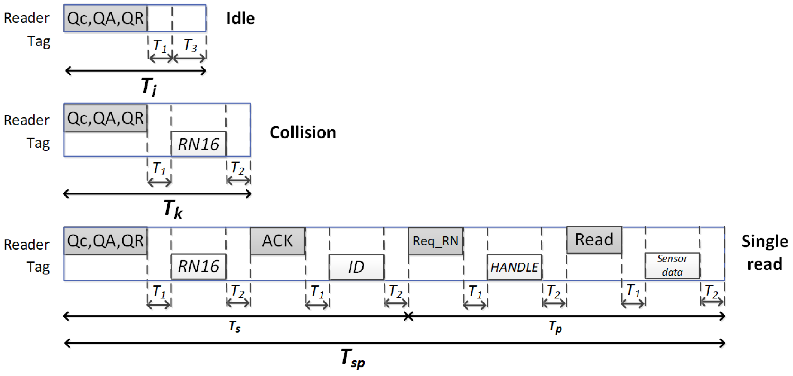
| , , | Link-timing parameters |
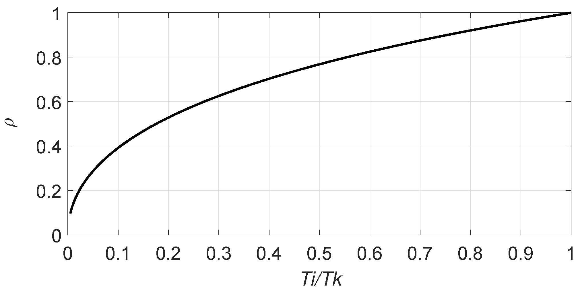
| , , | Duration of idle, single read, and collision slots |
| , , , , | Reader commands duration |
| , , , | Tags messages duration |
| , , | Number of idle, single, and collision slots in one frame |
| , , | Number of idle, single, and collision slots in one inventory round |
| Probability that r among n tags occupies a slot in a frame of size L | |
| , , | Probability of idle, single, and collision slot in a frame of size L |
| , , | Expected value of the number of idle, single, and collision slots in one frame |
| Time to read one sensor data packet from one tag | |
| Expected time to read one sensor data packet from one tag among n in a frame of size L |
| Scenario | S1 | S2 |
|---|---|---|
| n | [64–8192] tags * | [64–8192] tags |
| 40 kbps | [40–640] kbps * | |
| s | s | |
| s | [15.63–62.50] s | |
| s | [17.34–69.38] s | |
| s | [16.06–24.50] s | |
| s | [23.44–375.50] s | |
| s | s |
| (ms) | |||||
|---|---|---|---|---|---|
| * (kbps) | 40 | 80 | 124 | 274 | 640 |
| 0.25 | 0.32 | 0.39 | 0.53 | 0.69 | |
| FFSA | 35.14 | 18.30 | 12.30 | 6.30 | 3.46 |
| SUBEP-Q | 36.84 | 19.04 | 12.73 | 6.46 | 3.50 |
| Chen16 | 36.74 | 18.34 | 12.32 | 6.32 | 3.48 |
| FuzzyQ | 36.52 | 18.87 | 12.64 | 6.43 | 3.49 |
| Chen14 | 38.01 | 19.63 | 13.13 | 6.65 | 3.59 |
| Eom | 36.97 | 19.10 | 12.78 | 6.48 | 3.51 |
| ILCM-SbS | 36.05 | 18.66 | 12.50 | 6.38 | 3.48 |
| ILCM-FbF | 37.57 | 19.40 | 12.98 | 6.58 | 3.56 |
| Slot Counter | 37.12 | 19.20 | 12.85 | 6.53 | 3.55 |
© 2020 by the authors. Licensee MDPI, Basel, Switzerland. This article is an open access article distributed under the terms and conditions of the Creative Commons Attribution (CC BY) license (http://creativecommons.org/licenses/by/4.0/).
Share and Cite
Arjona, L.; Landaluce, H.; Perallos, A.; Onieva, E. Dynamic Frame Update Policy for UHF RFID Sensor Tag Collisions. Sensors 2020, 20, 2696. https://doi.org/10.3390/s20092696
Arjona L, Landaluce H, Perallos A, Onieva E. Dynamic Frame Update Policy for UHF RFID Sensor Tag Collisions. Sensors. 2020; 20(9):2696. https://doi.org/10.3390/s20092696
Chicago/Turabian StyleArjona, Laura, Hugo Landaluce, Asier Perallos, and Enrique Onieva. 2020. "Dynamic Frame Update Policy for UHF RFID Sensor Tag Collisions" Sensors 20, no. 9: 2696. https://doi.org/10.3390/s20092696
APA StyleArjona, L., Landaluce, H., Perallos, A., & Onieva, E. (2020). Dynamic Frame Update Policy for UHF RFID Sensor Tag Collisions. Sensors, 20(9), 2696. https://doi.org/10.3390/s20092696