Abstract
In many applications, modern current-using equipment utilizes power electronic converters to control the consumed power and to adjust the motor speed. Such equipment is used both in industrial and domestic installations. A characteristic feature of the converters is producing distorted earth fault currents, which contain a wide spectrum of harmonics, including high-order harmonics. Nowadays, protection against electric shock in low-voltage power systems is commonly performed with the use of residual current devices (RCDs). In the presence of harmonics, the RCDs may have a tripping current significantly different from that provided for the nominal sinusoidal waveform. Thus, in some cases, protection against electric shock may not be effective. The aim of this paper is to present the result of a wide-range laboratory test of the sensitivity of A-type RCDs in the presence of harmonics. This test has shown that the behavior of RCDs in the presence of harmonics can be varied, including the cases in which the RCD does not react to the distorted earth fault current, as well as cases in which the sensitivity of the RCD is increased. The properties of the main elements of RCDs, including the current sensor, for high-frequency current components are discussed as well.
1. Introduction
Electrical and electronic systems from their nature introduce an electric shock hazard. Thus, one of the most important things during the design of such systems is to apply to them effective protection against electric shock. The fundamental rule of electrical safety, both in high- and low-voltage systems, is included in standard EN 61140 [1]: Hazardous-live-parts are not allowed to be accessible, and accessible conductive parts are not allowed to be hazardous-live. For low-voltage systems, detailed rules referring to the protection against electric shock are described in the multipart standard IEC/HD 60364 “Low-voltage electrical installations,” especially in part HD 60364-4-41 [2]. For safety purposes, protection against direct contact (basic protection) and protection against indirect contact (fault protection) have to be used. The most common method of protection against indirect contact is the automatic disconnection of supply. In the case of a line-to-earth fault, dangerous voltage may appear at the metallic enclosure of the current-using equipment, and risk of electrocution, due to indirect contact, exists (Figure 1). To prevent a fatal accident, the power supply has to be disconnected within the time specified in standard HD 60364-4-41 [2] (e.g., in a TN-type low-voltage system, up to 0.4 s for final circuits rated up to 32 A). As a disconnecting device, a residual current device (RCD) may be used. Such a device is the only safety technical measure in the case of direct contact of a live conductor or in the case of touching a line terminal of current-using equipment (load) (Figure 1). Direct contact means that all the current-to-earth flows through the human body. There is no insulation fault; therefore, the body current is too low to activate an overcurrent protective device (miniature circuit-breaker (MCB) in Figure 1) and to switch off the supply. Only a reliable, high-sensitivity RCD may prevent a person from fatal electric shock, provided that the RCD’s rated residual operating current does not exceed 30 mA, which is assumed as the threshold of ventricular fibrillation [3].
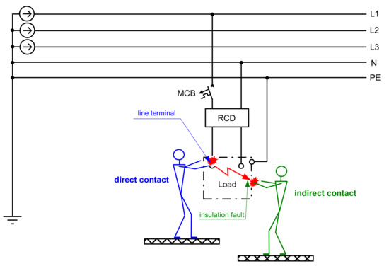
Figure 1.
Electric shock due to direct contact with live parts or due to insulation fault (indirect contact); RCD, residual current device; MCB, overcurrent protective device (miniature circuit-breaker).
To detect an insulation fault, especially a line-to-earth fault, which potentially introduces an electric shock hazard or fire hazard, a suitable protective device of a proper sensitivity level should be selected and applied. The type of protective device and its operational algorithm depends on the type of power network (grounded, ungrounded, overhead line, cable line) [4,5], the necessity of detection of an arc fault [6,7], distorted voltages [8], special signals [9], DC currents [10,11], and the necessity of detection of non-sinusoidal alternating earth fault currents. Special attention should be given to the currents comprising very-low-frequency components [12] or high-order harmonics [13,14,15,16,17,18,19], as in circuits with power electronics converters [20]. If residual current devices are used (they are even obligatory in some circuits), their sensitivity to the non-sinusoidal earth fault (residual) currents has to be verified. The variable-speed drive circuits are the most controversial from the point of view of the selection and operation of RCDs. These circuits generate mixed-frequency earth fault currents [21], the spectrum of which depends on the pulse width modulation (PWM) frequency and actual motor speed. In practical applications, the PWM frequency can be within the range of a few to over 20 kHz. The higher the PWM frequency, the worse the condition for the operation of RCDs. Such currents containing the high-frequency components make tripping characteristics of the most popular RCDs differ from those for the nominal 50/60 Hz [22]. The result of the test of the simplest RCD type presented in [23] shows that their tripping threshold depends on both the RCDs’ magnetic properties of the current sensor and the configuration of the tripping circuit. The increased tripping threshold of RCDs, which can be dangerous for the effectiveness of protection against electric shock, is also noted in the paper [24], and the authors propose a modification of the structure of the RCDs. After modification, proper operation of the analyzed RCD is obtained, but only for a frequency not much higher than the nominal. The problem of the RCD’s operation in the presence of harmonics is indicated in the guide [25]; it strongly underlines that the selection of RCDs to circuits with distorted earth fault current requires a detailed analysis of the earth fault current shapes. The selected RCD has to be able to react to them and, simultaneously, has to be immune to natural earth leakage currents. The manufacturer [25] even recommends special types of RCDs to such circuits. An advanced type of RCD (B-type) is studied in [26], but it is a relatively expensive RCD and used only in specific applications.
The international standards [27,28,29] recognize the following types of RCDs from the point of view of their sensitivity to the waveform shape:
- AC-type: Intended for 50/60 Hz sinusoidal residual currents only,
- A-type: Intended for waveforms, the same as for AC-type RCDs, and for DC-pulsating residual currents with a smooth DC component up to 6 mA,
- F-type: Intended for waveforms, the same as for A-type RCDs (but smooth DC component can be increased, up to 10 mA) and mixed-frequency residual currents; the RCD should be supplied from a single-phase.
- B-type: Intended for residual currents: Sinusoidal up to 1000 Hz, mixed-frequency, pulsating DC, as well as smooth DC.
It can be assumed that A-type RCDs are now the most popular RCDs utilized in low-voltage systems. At least such a type of RCD has to be used in some countries, e.g., in Germany and Denmark [30,31]. The A-type RCDs are also installed in circuits with power electronic converters, but, from the author’s experience, in some cases, such RCDs may not give effective protection against electric shock.
The aim of this paper is to present and comment on the results of the wide laboratory test of the A-type RCD’s sensitivity to the non-sinusoidal earth fault (residual) currents. The laboratory test shows that the sensitivity of the A-type RCDs depends on the order and content of the harmonic, and their real tripping current may significantly exceed the normative threshold provided for the 50 Hz sinusoidal waveform. The negative impact of harmonics on the RCDs’ current sensor and the tripping relay is discussed. Moreover, unexpected positive responses of the RCDs to the strongly distorted special residual current waveforms are presented. Detailed analysis of the operation of RCDs under non-sinusoidal current contributes to a more accurate evaluation of the effectiveness of protection against electric shock in modern low-voltage electrical circuits, as well as indicates a direction in the necessary modification of the structure of the RCDs in order to achieve better tripping parameters in the presence of harmonics.
2. The Scope of the Investigation and Its Results
2.1. General Information
A residual current device should be connected to the live conductors (line L and neutral N), as it is presented in Figure 2. The protective conductor PE has to go outside the RCD. In the case of an earth fault in the protected circuit, the earth fault current iΔ (residual current for the RCD) is a source of an unbalanced current state in the current sensor (summation current transformer) and produces magnetic flux in its iron core. The magnetic flux produces secondary voltage es, which is a source of secondary current is flowing through the relay. The relay mainly comprises a permanent magnet, a coil, a spring, and a moving element. The most common utilized RCDs have a rated residual operating current of IΔn = 30 mA, and they are voltage-independent. This means that the power necessary for operation of the RCDs is derived only from the residual current. In the case of 30 mA RCDs, the power delivered to the relay is extremely low, so it forces the utilization of the relays, especially with the permanent magnet.
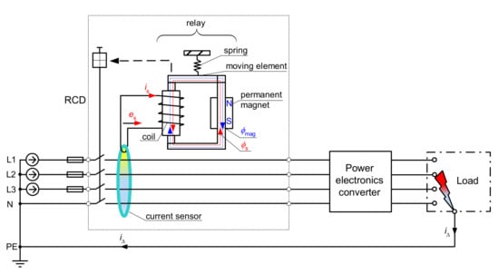
Figure 2.
Residual current device (RCD) protecting a 3-phase circuit; es—induced voltage in the secondary winding of the current sensor, is—secondary current flowing through the relay, φmag—magnetic flux from the permanent magnet, φs—magnetic flux from the secondary current, iΔ—residual current.
When there is no residual current in the protected circuit, the permanent magnet producing the magnetic flux φmag keeps the moving element of the relay in the closed position. While a residual current flows, the secondary current is produces magnetic flux φs that is superimposed on the flux φmag (see respective lines in the relay in Figure 2). If the magnetic flux is sinusoidal, in the one half-wave, it has the same direction as the constant-value magnetic flux from the permanent magnet. In turn, in the second half-wave, the magnetic flux φs has the opposite direction and reduces the flux φmag. If this reduction is significant, the spring pulls away from the moving element of the relay, and by consequence, the main circuit becomes open.
In circuits with distorted residual currents, the tripping threshold of the RCDs changes. The next section presents a theoretical analysis of the RCDs’ relay operation when the residual current, as well as the secondary current, comprises the following components:
- fundamental + 3rd harmonic (content 50%); phase angle of the 3rd harmonic: 0°, 45°, 90°, 180°;
- fundamental + 11th harmonic (content 50%); phase angle of the 11th harmonic: 0°, 45°, 90°, 180°;
- fundamental + 49th harmonic (content 50%); phase angle of the 49th harmonic: 0°, 180°.
After this, the results of the laboratory test are presented. The tripping threshold of a group of A-type RCDs has been evaluated, for the following testing currents:
- fundamental + 3rd harmonic,
- fundamental + 5th harmonic,
- fundamental + 7th harmonic,
- fundamental + 11th harmonic,
- fundamental + 23rd harmonic,
- fundamental + 49th harmonic.
The above-mentioned harmonics were selected (as an example) to test based on the study of the literature, as well as from the practical experience of the author. Relatively high-frequency harmonics (here, 23rd and 49th) reflect the components produced by a power converter modulation (PWM frequency, its multiple and interharmonics).
During this test, the content of the harmonic (with reference to the fundamental) was consecutively forced: 50%, 100%, and 200%, and the phase angle of the harmonic was consecutively set to 0°, 45°, 90°, 135°, 180°, 225°, 270°, and 315°.
The tripping threshold of the two selected RCDs has also been verified for testing waveforms comprising many harmonics (as in a circuit with variable-speed drives). Furthermore, for comparison of the behavior of the RCDs, their tripping threshold under a special distorted waveform—bidirectional waveform characterized by various trigger delay angles—is presented as well.
Finally, the main sources of the changes in the tripping threshold of RCDs in circuits with distorted residual currents are presented and discussed.
2.2. Theoretical Analysis of the RCDs’ Relay Operation in the Presence of Harmonics
Distorted residual current can be described by the following dependency:
where:
iΔ =⋅IΔamp ⋅[sin(ωt + ψ1) + C3 ⋅ sin(3ωt + ψ 3) + C5 ⋅ sin(5ωt + ψ 5) + … + Ch ⋅ sin(hωt + ψ h)]
iΔ : Residual current as a function of time,
IΔ amp : Amplitude of the residual current,
C3, C5, … Ch : The content of the amplitude-to-fundamental for the 3rd, 5th, …, h-th harmonic
ψ3, ψ5, … ψ h : Phase angle of the 3rd, 5th, …, h-th harmonic.
However, the operation of the relay of the RCD (Figure 2) depends on the secondary current is, which flows at the secondary side of the current sensor. To verify the transformation quality of the iron core of the A-type current sensor, a laboratory test of the induced secondary voltage es, generated by the distorted residual current iΔ, has been performed. It may be concluded that the shape of the induced voltage es is relatively divergent with the shape of the residual current iΔ; Figure 3 presents, as an example, a selected result of this test when the residual current iΔ is composed of the fundamental (50 Hz) and the 50% content of the 11th harmonic. In further analysis, it is assumed that the secondary current is has a similar shape as the residual current iΔ.
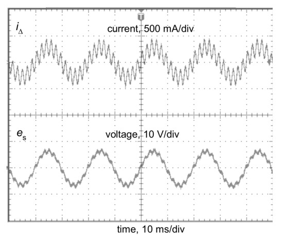
Figure 3.
Oscillogram of the induced secondary voltage es in the secondary winding of the current sensor from a 300 mA A-type RCD for the residual current iΔ composed of the fundamental (50 Hz) and 50% content of the 11th harmonic.
The secondary current is flowing in a coil, which is a part of the RCD’s relay, produces magnetic flux φs:
where:
is : Current, which flows at the secondary side of the current sensor,
nc : Number of turns in the relay coil,
Rm : The reluctance of the relay magnetic path.
Further, the magnetic force Fs generated by the magnetic flux φs in the relay can be described by the following expression [32]:
where:
φs : Magnetic flux generated by the secondary current is,
score : Cross-sectional area of the relay core,
μ0 : Magnetic constant (permeability of vacuum),
but the magnetic force Fmag from the magnetic flux φmag produced by the permanent magnet is represented by the following formula:
where:
φmag : Magnetic flux generated by the permanent magnet,
score : Cross-sectional area of the relay core,
μ0 : Magnetic constant (permeability of vacuum).
Assuming that the spring pulls the moving element of the relay with the force Fspring, the resultant force Fres from the interaction, permanent magnet–spring–secondary current, is as follows:
Theoretical analysis of the operation of the RCDs’ relay is conducted graphically (Figure 4, Figure 5 and Figure 6). In every figure, a reference magnetic force from the sinusoidal current (dotted line) is included, and on its background, the force produced by a non-sinusoidal current is presented. All forces are scaled in relative units.
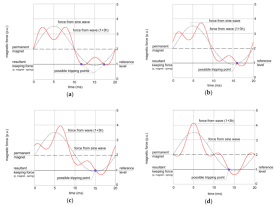
Figure 4.
Interaction between forces in the electromechanical relay of the RCD for earth fault current waveforms comprising the fundamental and 50% of the 3rd harmonic. Phase angle of the 3rd harmonic: (a) 0°; (b) 45°; (c) 90°; (d) 180°.
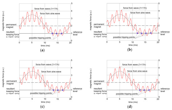
Figure 5.
Interaction between forces in the electromechanical relay of the RCD for earth fault current waveforms comprising the fundamental and 50% of the 11th harmonic. The phase angle of the 11th harmonic: (a) 0°; (b) 45°; (c) 90°; (d) 180°.

Figure 6.
Interaction between forces in the electromechanical relay of the RCD for earth fault current waveforms comprising the fundamental and 50% of the 49th harmonic. The phase angle of the 49th harmonic: (a) 0°; (b) 180°.
Figure 4 presents an analysis of the relay operation in the case of the waveform comprising the fundamental and the 3rd harmonic. In all the analyses, the content of the higher harmonics is 50% (percentage-to-fundamental; the fundamental has 50 Hz). If the subfigures (a), (b), (c), and (d) from Figure 4 are compared, one can see that the peak value of the force generated by the non-sinusoidal current depends on the phase angle of the higher harmonics.
In Figure 4a, the force from the wave 1+3h with phase angle 0° crosses the resultant keeping force from the permanent magnet and the spring but only with a slight excess. In the case of Figure 4d (the wave 1+3h with phase angle 180°), this excess is the highest. The tripping threshold of the relay depends on the peak value of the secondary current; therefore, for the waveform from Figure 4a, the tripping current of the RCD is expected to be higher (worse sensitivity) than for the waveform from Figure 4d.
The analyzed waveform comprising the fundamental and the 11th harmonic gives different conclusions (Figure 5). The effect of the higher harmonic phase angle is not as significant as in the case of the 3rd harmonic; the peak value of the force produced by the non-sinusoidal current is almost the same in every case from Figure 5.
Even less influence of the phase angle of the higher harmonics is observed for the 49th harmonic (Figure 6). The shapes of the force waveform are practically the same regardless of the value of the phase angle of the 49th harmonic; it should give the same level of tripping current for all the phase angles.
2.3. Laboratory Verification of the Tripping Current in the Presence of Harmonics
The sensitivity of the A-type RCDs (IΔn = 30, 100, and 300 mA) has been tested with the use of the laboratory stand, the general structure of which is presented in Figure 7. This paper includes the results of the test for the eight RCDs, which are representative and the most interesting.
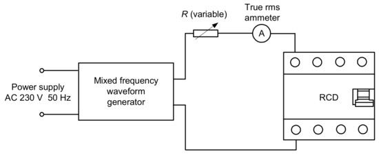
Figure 7.
Diagram of the laboratory stand for RCD testing.
During the first part of the test, the mixed-frequency waveform generator has been utilized for the production of the fundamental waveform and one of the following harmonics: 3rd, 5th, 7th, 11th, 23rd, and 49th. The content of the particular harmonic was consecutively set to 50%, 100%, and 200% with reference to the fundamental. The phase angle of the harmonic was set within the range 0°–315° with a 45° step. The mixed-frequency current was slowly increased with the use of the resistor R. As a reference value, the tripping current of each RCD was checked for the 50 Hz sinusoidal waveform. According to the standard [28], the tripping current for the sinusoidal waveform should be within the range (0.5–1.0)IΔn, i.e., 15–30 mA for an RCD of IΔn = 30 mA. Figure 8, Figure 9, Figure 10, Figure 11 and Figure 12 present the results of this part of the test for selected RCDs, and the aforementioned range is marked as a shaded area.
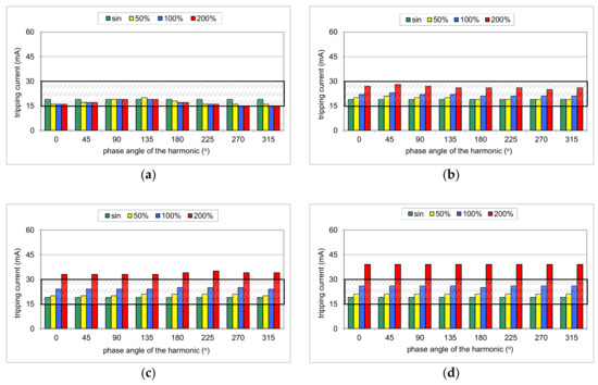

Figure 8.
Tripping current of the A-type 30 mA RCD (no. RCD30_1) for testing waveform comprising the fundamental and the following high-frequency components: (a) 3rd harmonic; (b) 5th harmonic; (c) 7th harmonic; (d) 11th harmonic; (e) 23rd harmonic; (f) 49th harmonic. Tested percentages of harmonic-to-fundamental: 50%, 100%, and 200%, and phase angles of the harmonic: 0°, 45°, 90°, 135°, 180°, 225°, 270°, 315°.
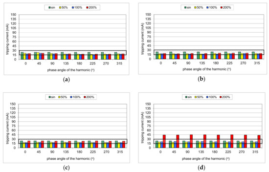

Figure 9.
Tripping current of the A-type 30 mA RCD (no. RCD30_2) for testing waveform comprising the fundamental and the following high-frequency components: (a) 3rd harmonic; (b) 5th harmonic; (c) 7th harmonic; (d) 11th harmonic; (e) 23rd harmonic; (f) 49th harmonic. Tested percentages of harmonic-to-fundamental: 50%, 100%, and 200%, and phase angles of the harmonic: 0°, 45°, 90°, 135°, 180°, 225°, 270°, 315°.
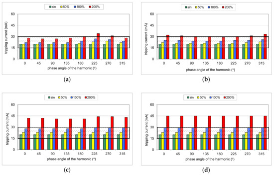

Figure 10.
Tripping current of the A-type 30 mA RCD (no. RCD30_3) for testing waveform comprising the fundamental and the following high-frequency components: (a) 3rd harmonic; (b) 5th harmonic; (c) 7th harmonic; (d) 11th harmonic; (e) 23rd harmonic; (f) 49th harmonic. Tested percentages of harmonic-to-fundamental: 50%, 100%, and 200%, and phase angles of the harmonic: 0°, 45°, 90°, 135°, 180°, 225°, 270°, 315°.
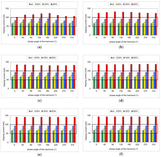
Figure 11.
Tripping current of the A-type 100 mA RCD (no. RCD100) for testing waveform comprising the fundamental and the following high-frequency components: (a) 3rd harmonic; (b) 5th harmonic; (c) 7th harmonic; (d) 11th harmonic; (e) 23rd harmonic; (f) 49th harmonic. Tested percentages of harmonic-to-fundamental: 50%, 100%, and 200%, and phase angles of the harmonic: 0°, 45°, 90°, 135°, 180°, 225°, 270°, 315°.
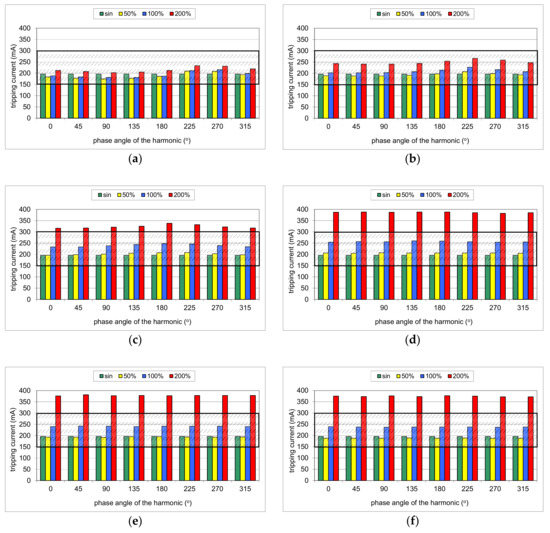
Figure 12.
Tripping current of the A-type 300 mA RCD (no. RCD300_1) for testing waveform comprising the fundamental and the following high-frequency components: (a) 3rd harmonic; (b) 5th harmonic; (c) 7th harmonic; (d) 11th harmonic; (e) 23rd harmonic; (f) 49th harmonic. Tested percentages of harmonic-to-fundamental: 50%, 100%, and 200%, and phase angles of the harmonic: 0°, 45°, 90°, 135°, 180°, 225°, 270°, 315°.
The result of the tests of RCD30_1 (Figure 8) shows that its tripping threshold for the testing waveform containing the 3rd harmonic depends on the phase angle of this harmonic, which confirms the above-conducted theoretical analysis. In any of the trials, the tripping threshold is within the normative range as for the sinusoidal waveform (0.5–1.0)IΔn (Figure 8a). For the phase angle of the 3rd harmonic equal to 270° or 315°, the RCD tripped almost at the lower permissible limit 0.5IΔn when the content of the harmonic was 100% or 200%. In these cases, it is a kind of increase in RCD sensitivity.
The effect of the phase angle of the higher harmonic on the tripping current is also noticeable in the case of the 5th harmonic (Figure 8b). However, the content of the harmonic equal to 100% or 200% makes that tripping threshold rise in comparison to a pure sinusoidal waveform. For a content of 200%, it is close to the upper limit 1.0IΔn. For the other harmonics (7th, Figure 8c; 11th, Figure 8d; 23rd, Figure 8e; 49th, Figure 8f, the tripping current for a particular harmonic does not depend on the phase angle of the harmonic, which confirms the theoretical analysis as well. However, for a high content of the harmonic (200%), RCD30_1 tripped at a level higher than the upper limit (30 mA). It signifies that in the adverse condition (high content of higher-order harmonics), such an RCD may not give sufficient protection against electric shock.
The problem of the strongly increased tripping threshold is clearly seen in the case of RCD30_2 (Figure 9). As far as for harmonics 3rd (Figure 9a), 5th (Figure 9b), and 7th (Figure 9c), this RCD reacts very well (within the range of 0.5–1.0IΔn), but for the other harmonics, especially for a content of 200% of the 23rd or the 49th harmonic, the tripping current rises rapidly. For the 49th harmonic, it is around 6–7 times higher than for the pure sine waveform.
More even tripping characteristics are observed for RCD30_3 (Figure 10), especially for harmonics 11th, 23rd, and 49th. These three groups of results (Figure 10d–f) are almost the same. Furthermore, for the highest content (200%) of the aforementioned harmonics (11th, 23rd, and 49th), the tripping threshold is stable (around 45 mA). Unfortunately, what is unexpected is that the content of 200% of the 3rd harmonic (relatively low-order harmonic) may give a tripping current exceeding 30 mA (upper limit for the 50 Hz sine wave) (Figure 10a).
Similar tripping behavior is noticed in the case of RCD100 (Figure 11). However, an unfavorable effect of the harmonics is recorded even for the relatively low-order harmonics. In the case of the 3rd harmonic and its content equal to 200%, the tripping threshold is higher than IΔn = 100 mA for every tested phase angle.
The test of RCD300_1 (Figure 12) has given typical expected results; relatively low-order harmonics (here 3rd and 5th) superimposed on the fundamental give a real tripping current dependent on the phase angle of the harmonic, but it is kept within the range (0.5–1.0)IΔn. High-order harmonics (11th, 23rd, and 49th), with their content very high, result in a tripping current that exceeds the upper limit 1.0IΔn.
The tripping current has also been tested for the testing waveform comprising many harmonics. Figure 13 presents oscillograms of the earth fault current at the terminal of the motor supplied via a frequency converter (variable-speed drive circuit). The earth fault was carried out through the resistance 1 kΩ—it reflects direct contact of a human with the live conductor. The PWM frequency is equal to 3 kHz. The earth current is built from low-order harmonics, as well as very-high-order harmonics resulting from the PWM frequency. Note that this current also contains a multiple of the PWM frequency, even above 20 kHz here. Moreover, the spectrum of the waveform depends on the actual motor speed (nominal motor speed, Figure 13a; very low motor speed, Figure 13b). The highest content of high-order harmonics occurs for very low motor speed (1 Hz). In the test of the operation of the RCDs, their tripping current has been verified for the earth current waveforms (reflected in the laboratory generator) occurring in the case of the nominal motor speed (50 Hz), decreased motor speed (25 Hz), and strongly decreased motor speed (1 Hz). The PWM frequency was adopted to be equal to 1 kHz.
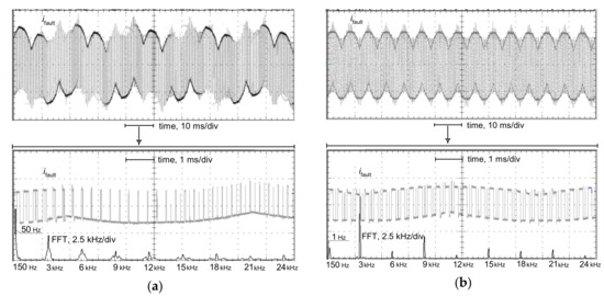
Figure 13.
Oscillograms of the line-to-earth fault current waveform ifault and its FFT analysis in the case of an earth fault at the output terminals of the frequency converter supplying a motor: (a) operating frequency of 50 Hz (nominal motor speed); (b) operating frequency of 1 Hz (very low motor speed); pulse width modulation (PWM) frequency of 3 kHz; line-to-earth connection via resistance of 1 kΩ (conventional human body resistance).
Results of the test of two 30 mA RCDs, for the multiple-harmonics testing current, are presented in Figure 14. For the earth current waveform occurring during nominal motor speed (50 Hz), both tested RCDs have a tripping current not exceeding 30 mA. In the case of the supplying frequency reflecting decreased motor speed (25 Hz), the tripping current of RCD30_2 is 44 mA, whereas that of RCD30_4 is as much as 145 A. Very unfavorable behavior of RCD30_2 was observed in the case of the testing waveform reflecting the strongly decreased motor speed (1 Hz). The maximal forced testing current was over 3 A (one hundred times higher than the rated residual operating current of the tested RCDs), but RCD30_2 did not operate. Fortunately, RCD30_4 tripped, but at 320 mA. This test has shown that the behavior of A-type RCDs in the presence of harmonics can be unexpected. Current harmonics, especially high-order harmonics, increase the tripping threshold of the RCDs; in some cases, the RCDs may not react to the earth fault currents having a relatively high content of high-order harmonics. Additionally, some RCDs may have increased tripping current even in the presence of relatively low-order harmonics (3rd, 5th, or 7th).
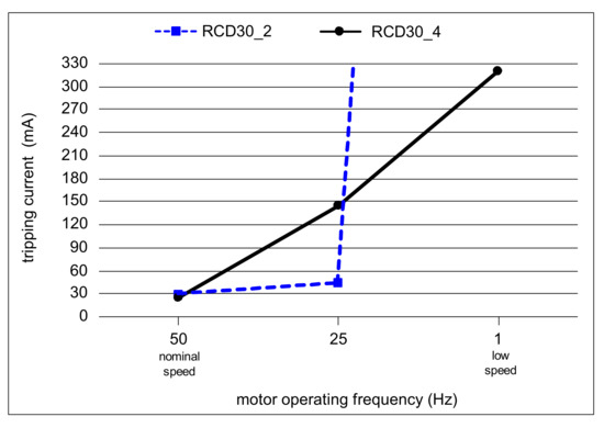
Figure 14.
Tripping current of two RCDs (IΔn = 30 mA) for testing currents comprising many harmonics as in a variable-speed drive circuit.
2.4. Discussion: Sources of the Varied Tripping Current in the Presence of Harmonics
Analysis of the effect of harmonics on the main elements of the RCDs is conducted based on the equivalent circuit presented in Figure 15. In the analysis, the most important are as follows:
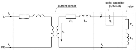
Figure 15.
Equivalent circuit of the RCD; iΔ—residual (primary) current, is—secondary current, es— voltage induced in the secondary winding of the current sensor, Rs—resistance of the secondary winding, Ls—inductance of the secondary winding, RR—resistance of the relay, LR—inductance of the relay, Cs—serial capacitor (optional).
- magnetic properties of the current sensor (transformer) for various frequencies,
- the configuration of the secondary circuit: Whether only the relay is installed or additional electronic elements (capacitors serial/parallel) are installed as well,
- parameters of the relay, especially for various frequencies.
To verify the magnetic properties of the current sensor of the RCDs, hysteresis loops of the selected A-type current sensor (from the RCD of IΔn = 30 mA) have been measured for the following frequencies: 50, 150, and 1000 Hz. Results of the measurements are presented in Figure 16.
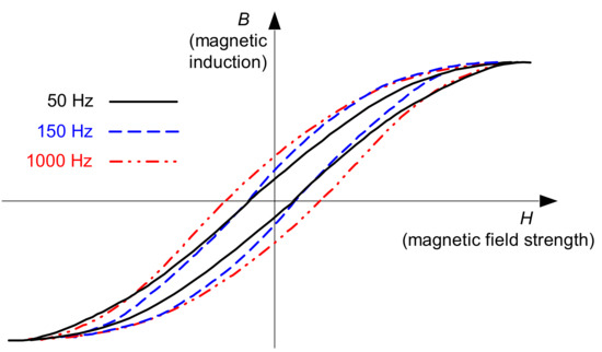
Figure 16.
Measured hysteresis loops of the current sensor of the 30 mA A-type RCD, for frequencies of 50, 150, and 1000 Hz.
One can see that for higher frequencies, the hysteresis loop shapes are different than for the fundamental frequency of 50 Hz. The most important is the fact that for the relatively high frequency (1000 Hz), the shape is wider compared to 50 Hz. Thus, to achieve sufficient magnetic induction for such a high frequency, magnetic field strength has to be higher than for the nominal/fundamental frequency. It can be one of the sources of the significantly higher tripping current of the tested RCDs when the testing waveform contains the 23rd or 49th harmonic (see Figure 8, Figure 9, Figure 10, Figure 11 and Figure 12).
Additional matching elements (as capacitors) in the secondary circuit of the RCD may also influence the RCDs tripping negatively in the presence of high-frequency components. Figure 17 presents results of the previous investigations [33], in which the secondary current waveform was simulated in the circuit without a serial matching capacitor (Figure 17a) and with this capacitor (Figure 17b). This capacitor gives the possibility for delivering the increased power (increased secondary current, especially the peak value, which is the most important) to the relay. This improves the sensitivity of the RCDs. Increased secondary current, in comparison to the case without the capacitor, has been obtained, but only for the fundamental frequency 50 Hz (compare black traces: Figure 17a versus Figure 17b). The favorable effect of the capacitor in the secondary circuit of the RCD is practically not observed for the other tested frequencies: 150 and 1000 Hz. The corresponding current waveforms are almost identical.
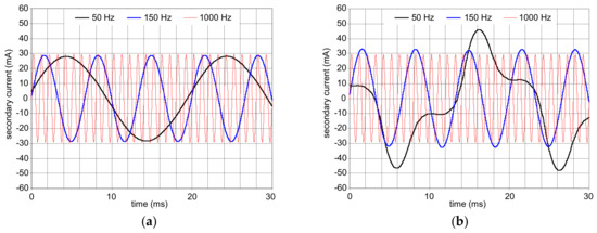
Figure 17.
Results of the computer simulations of the secondary current (is in Figure 2) flowing through the electromechanical relay: (a) No serial capacitor in the secondary circuit; (b) serial capacitor in secondary circuit is applied; values of the residual current frequency: 50, 150, and 1000 Hz [33].
The secondary current value also depends on the induced secondary voltage es and the impedance of the relay, as a function of the frequency. Induced secondary voltage es in the secondary winding of the current sensor can be described by the following equation:
where:
es = 4.44 ns f φM,
ns : Number of turns in the secondary winding of the current sensor,
f : Frequency of the current waveform,
φM : The magnetic flux in the core of the current sensor, coupled with the primary winding and the secondary winding of the current sensor.
Theoretically (ideally), the induced voltage es should vary in the same way as the frequency f varies. In practice, this dependence is different. Figure 18 presents results of the measured induced voltage (relative, with reference to those for the frequency of 50 Hz) for the A-type current sensor. One can see that the variation in frequency from 50 to 1000 Hz (20×) gives an increase in the induced voltage of only around 14 times. This phenomenon, as well as increasing impedance of the relay as a function of frequency (Figure 19), may result in the increased tripping current of A-type RCDs for the earth fault currents with harmonics, especially high-order harmonics.
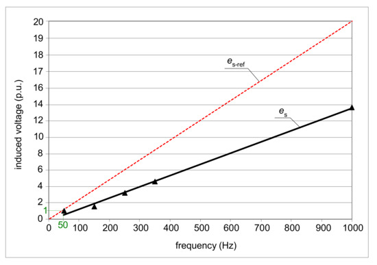
Figure 18.
Variation (measured) in the induced secondary voltage es of the A-type current sensor for the frequency range of the residual current f = 50–1000 Hz; es-ref (dotted red line), reference line for an ideal current sensor (transformer).
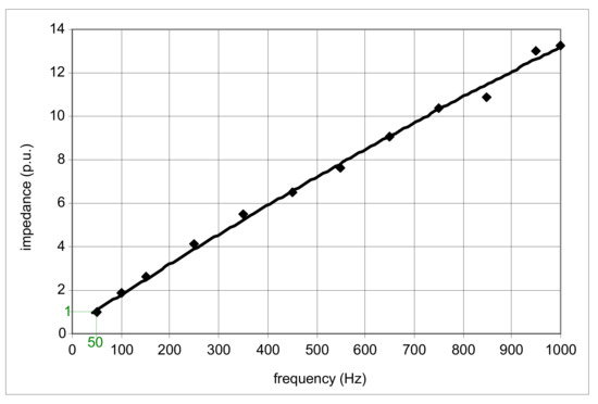
Figure 19.
Impedance variation (measured) of the example relay (just before tripping) of the 30 mA A-type RCD, within the frequency range f = 50–1000 Hz.
3. Behavior of RCDs under Residual Currents with Controlled Delay Angle
Power control of current-using equipment may be realized with the use of electronic converters, which control the delay angle of the load current. This way of power control is used, among others, in lighting circuits. The higher the value of the current delay angle, the more distorted the current. Taking into account the above considerations, related to the behavior of RCDs in the presence of harmonics, the first conclusion may appear that strongly distorted residual current, having a high delay angle value, would also give deteriorated sensitivity of the RCD, even above the upper limit 1.0IΔn. To verify this assumption, a laboratory test of two 300 mA A-type RCDs was conducted for the following current delay angles of the residual current: 0°, 45°, 90°, and 135°, and its results are presented in Figure 20.
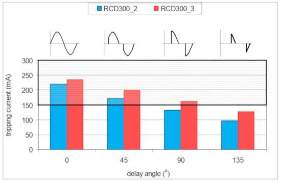
Figure 20.
Tripping current of two 300 mA A-type RCDs for the following current delay angles: 0°, 45°, 90°, and 135°.
For a sinusoidal testing current (current delay angle equal to 0°), the tripping current of both the tested RCDs is almost in the middle of the normative characteristic (0.5–1.0)IΔn. However, the higher the value of the current delay angle, the lower the tripping current. What is interesting is that for a current delay angle equal to 90°, the tripping current of the RCD300_2 is below the lower limit 0.5IΔn assigned to the sinusoidal waveform. In the case of the angle 135°, both tested RCDs have a tripping current below this limit. Thus, strongly distorted symmetrical residual current, having a high value of the delay angle, is very easily detected by the A-type RCDs. The effective protection against electric shock is not compromised; only unexpected nuisance tripping of the RCDs, for high values of the delay angle, may occur.
Tripping current of the tested RCDs, under the lower limit of 0.5IΔn, is associated with the relation of the peak value of the current waveform to its rms value. One must remember that the tripping threshold of the RCDs depends on the peak value of the residual current. If the residual current has increased current delay angle, the ratio peak-to-rms is higher than for a sinusoidal waveform. Figure 21 presents oscillograms of the induced secondary voltage es in the secondary winding of the current sensor dismounted from a 300 mA A-type RCD. In both cases (delay angle 0° and 135°), the same rms value of the residual current is forced. It is not difficult to notice that the delay angle equal to 135° gives a significantly higher peak value of the induced voltage than the case with a delay angle of 0°. For this reason, the tripping threshold of the RCDs, which depends on the peak value, is expected to be relatively low (for the angle of 90° or 135°), even below 0.5IΔn.
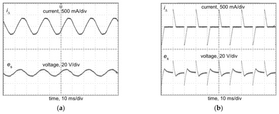
Figure 21.
Oscillograms of the induced secondary voltage es in the secondary winding of the current sensor from a 300 mA A-type RCD, for the following current delay angles of the residual current: (a) 0°; (b) 135°; in both cases, the rms values of the residual current iΔ are the same.
4. Conclusions
Residual current devices are commonly used in modern low-voltage electrical installations. Their application in circuits of increased electric shock risk is even obligatory. However, the wide-spread application of current-using equipment supplied via power electronics converters makes proper operation of the most popular RCDs—A-type RCDs—doubtful. The most problematic RCD operation is expected in circuits utilizing high-frequency PWM modulation. The earth fault current comprises high-order harmonics, and the tripping current of the RCD can be very high; it can be many times higher than its rated residual operating current. For one of the tested RCDs (RCD30_4), having a rated residual operating current IΔn = 30 mA, the tripping threshold was 320 mA (Figure 14). Even worse, some RCDs may not react to the non-sinusoidal current of a high content of high-order harmonics, as it has been shown in the above-presented investigations that no reaction was obtained in case of RCD30_2. In such circuits, protection against electric shock may not be effective. On the other hand, strongly distorted earth fault current, characterized by symmetrical delay angle, causes an opposite reaction of the RCDs; the tripping threshold can be clearly lower than for the sinusoidal waveform. During the laboratory test of the example RCD of IΔn = 300 mA (RCD300_2), its tripping current was equal to around 100 mA (delay angle 135°), whereas for the sinusoidal waveform, it was around 220 mA. Thus, evaluation of the protection against electric shock in the presence of harmonics, if RCDs are to be used, should be performed in detail, including their additional laboratory testing.
The conducted research also gives key information for the modification of the structure of voltage-independent RCDs, dedicated to the circuits characterized by earth fault current with harmonics, especially high-order harmonics. As the sensitivity of RCDs is mainly determined by the frequency response of both the current sensor and the electromechanical relay, the material used for construction of their magnetic path has to have favorable properties for higher frequencies (narrow hysteresis loop, low level of losses). Moreover, the coil of the relay should be suitable for higher frequencies—the lowest number of turns (as much as possible) is recommended to be applied. It gives a relatively low level of reactance that depends on the frequency. Special attention must be given to the selection of the additional components (e.g., capacitors) installed in the secondary circuit of the current sensor. Capacitors may give a positive effect for the nominal frequency (50 Hz), but for other frequencies, the effect may be quite opposite. The behavior of the secondary circuit, including the additional components, has to be verified within the frequency range to which the RCD is dedicated. After such verification, the permissible range of the operational frequency should be published by manufacturers of RCDs.
Funding
This research was supported by Gdańsk University of Technology.
Conflicts of Interest
The author declares no conflict of interest.
References
- IEC. IEC 61140:2016. Protection Against Electric Shock–Common Aspects For Installation and Equipment; International Electrotechnical Commission: Geneva, Switzerland, 2016. [Google Scholar]
- CENELEC. HD 60364-4-41:2017. Low-Voltage Electrical Installations–Part 4-41: Protection For Safety–Protection Against Electric Shock; European Committee for Electrotechnical Standardization: Brussels, Belgium, 2017. [Google Scholar]
- IEC. IEC TS 60479-1:2016 Effects Of Current On Human Beings And Livestock. Part 1: General Aspects; International Electrotechnical Commission: Geneva, Switzerland, 2016. [Google Scholar]
- Liu, Y.; Xie, X.; Hu, Y.; Qian, Y.; Sheng, G.; Jiang, X. A novel transient fault current sensor based on the PCB Rogowski coil for overhead transmission lines. Sensors 2016, 16, 742. [Google Scholar] [CrossRef] [PubMed]
- Granizo, R.; Blánquez, F.R.; Rebollo, E.; Platero, C.A. A novel ground fault non-directional selective protection method for ungrounded distribution networks. Energies 2015, 8, 1291–1316. [Google Scholar] [CrossRef]
- Bao, G.; Gao, X.; Jiang, R.; Huang, K. A novel differential high-frequency current transformer sensor for series arc fault detection. Sensors 2019, 19, 3649. [Google Scholar] [CrossRef] [PubMed]
- Yang, K.; Zhang, R.; Chen, S.; Zhang, F.; Yang, J.; Zhang, X. Series arc fault detection algorithm based on autoregressive bispectrum analysis. Algorithms 2015, 8, 929–950. [Google Scholar] [CrossRef]
- Sułowicz, M.; Ludwinek, K.; Tulicki, J.; Depczyński, W.; Nowakowski, Ł. Practical adaptation of a low-cost voltage transducer with an open feedback loop for precise measurement of distorted voltages. Sensors 2019, 19, 1071. [Google Scholar] [CrossRef] [PubMed]
- Rabcan, J.; Levashenko, V.; Zaitseva, E.; Kvassay, M.; Subbotin, S. Application of fuzzy decision tree for signal classification. IEEE Trans. Ind. Inf. 2019, 15, 5425–5434. [Google Scholar] [CrossRef]
- Czapp, S. The impact of DC earth fault current shape on tripping of residual current devices. Elektronika ir Elektrotechnika 2008, 4, 9–12. [Google Scholar]
- Yao, W.; Kui, L.; Can, L.; Zhitao, G.; Feng, N.; Zhang, X. Study on modeling and simulation of AC/DC sensitive residual current transformer. In Proceedings of the 1st International Conference on Electric Power Equipment-Switching Technology, Xi’an, China, 23–27 October 2011. [Google Scholar] [CrossRef]
- Czapp, S.; Dobrzynski, K.; Klucznik, J.; Lubosny, Z. Low-frequency tripping characteristics of residual current devices. In Proceedings of the 2017 IEEE International Conference on Environmental and Electrical Engineering & 2017 IEEE Industrial and Commercial Power Systems Europe (EEEIC /I&CPS Europe), Milan, Italy, 6–9 June 2017; pp. 298–301. [Google Scholar] [CrossRef]
- Erdei, Z.; Horgos, M.; Lung, C.; Pop-Vadean, A.; Muresan, R. Frequency behavior of the residual current devices. In Proceedings of the International Conference on Applied Sciences ( ICAS2016), Hunedoara, Romania, 25–27 May 2016. [Google Scholar] [CrossRef]
- Freschi, F. High-frequency behavior of residual current devices. IEEE Trans. Power Deliv. 2012, 27, 1629–1635. [Google Scholar] [CrossRef]
- Czaja, P. Examination of the impact of design of a residual current protective device on the release frequency range. In Proceedings of the 2017 Progress in Applied Electrical Engineering (PAEE), Koscielisko, Poland, 25–30 June 2017. [Google Scholar] [CrossRef]
- Czapp, S.; Dobrzynski, K.; Klucznik, J.; Lubosny, Z.; Kowalak, R. Improving sensitivity of residual current transformers to high frequency earth fault currents. Arch. Elect. Eng. 2017, 66, 485–494. [Google Scholar] [CrossRef]
- Cocina, V.; Colella, P.; Pons, E.; Tommasini, R.; Palamara, F. Indirect contacts protection for multi-frequency currents ground faults. In Proceedings of the 2016 IEEE 16th International Conference on Environment and Electrical Engineering (EEEIC), Florence, Italy, 7–10 June 2016. [Google Scholar] [CrossRef][Green Version]
- Lee, T.M.; Chan, T.W. The effects of harmonics on the operational characteristics of residual current circuit breakers. In Proceedings of the International Conference on Energy Management and Power Delivery, Singapore, 21–23 November 1995; pp. 715–719. [Google Scholar] [CrossRef]
- Czapp, S. The effect of earth fault current harmonics on tripping of residual current devices. In Proceedings of the International School on Nonsinusoidal Currents and Compensation, IX Conference-Seminar (ISNCC), Lagow, Poland, 10–13 June 2008. [Google Scholar] [CrossRef]
- Wieland, T.; Aigner, M.; Schmautzer, E.; Pasker, J.; Fickert, L. Influences on safety issues for inverter supplied grid structures. In Proceedings of the 2012 Electric Power Quality and Supply Reliability, Tartu, Estonia, 11–13 June 2012. [Google Scholar] [CrossRef]
- Gruhn, T.; Glenney, J.; Savostianik, M. Type B ground-fault protection on adjustable frequency drives. IEEE Trans. Ind. Appl. 2018, 54, 934–939. [Google Scholar] [CrossRef]
- Czapp, S.; Guzinski, J. Electric shock hazard in circuits with variable-speed drives. Bull. Pol. Ac. Tech. 2018, 66, 361–372. [Google Scholar] [CrossRef]
- Czaja, P.; Pluta, W. Magnetic properties of additive transformer cores of residual current devices. Przeglad Elektrotechniczny 2019, 12, 109–112. [Google Scholar] [CrossRef]
- Horgos, M.; Erdei, Z.; Barz, C.; Birsan, I.; Ilia, M. Contributions to testing residual current devices at different frequency values. In Proceedings of the 6th International Conference on Modern Power Systems (MPS), Cluj-Napoca, Romania, 18–21 May 2015. [Google Scholar]
- Eaton. Residual Current Devices. In Application Guide; Eaton: Vienna, Austria, 2017. [Google Scholar]
- Panda, R.K.; Veeramalla, J. Behavior modeling of a type B RCD. In Proceedings of the 1st IEEE International Conference on Power Electronics, Intelligent Control and Energy Systems (ICPEICES), Delhi, India, 4–6 July 2016. [Google Scholar] [CrossRef]
- IEC. IEC 60755:2017. General Safety Requirements For Residual Current Operated Protective Devices; International Electrotechnical Commission: Geneva, Switzerland, 2017. [Google Scholar]
- IEC. IEC 61008-1:2010. Residual Current Operated Circuit-Breakers Without Integral Overcurrent Protection For Household And Similar Uses (RCCB)–Part 1: General Rules; International Electrotechnical Commission: Geneva, Switzerland, 2010. [Google Scholar]
- IEC. IEC 62423:2009. Type F And Type B Residual Current Operated Circuit-Breakers With And Without Integral Overcurrent Protection For Household And Similar Uses; International Electrotechnical Commission: Geneva, Switzerland, 2009. [Google Scholar]
- Field Test of Installed Residual Current Devices in Denmark; Sikkerhedsstyrelsen: Esbjerg, Denmark, 2009.
- Han, Y.; Ding, C.; Shou, X. Design & implementation of an A-type residual current circuit breaker IC. In Proceedings of the 2012 IEEE International Symposium on Industrial Electronics, Hangzhou, China, 28–31 May 2012. [Google Scholar] [CrossRef]
- VDM Metals GmbH. VDM Report Nr. 27 Weichmagnetische Werkstoffe auf Ni-Fe-Basis; VDM Metals GmbH: Werdohl, Germany, 2014. [Google Scholar]
- Czapp, S.; Horiszny, J. Simulation of residual current devices operation under high frequency residual current. Przeglad Elektrotechniczny 2012, 2, 242–247. [Google Scholar]
© 2020 by the author. Licensee MDPI, Basel, Switzerland. This article is an open access article distributed under the terms and conditions of the Creative Commons Attribution (CC BY) license (http://creativecommons.org/licenses/by/4.0/).