OMNIVIL—An Autonomous Mobile Manipulator for Flexible Production


Abstract
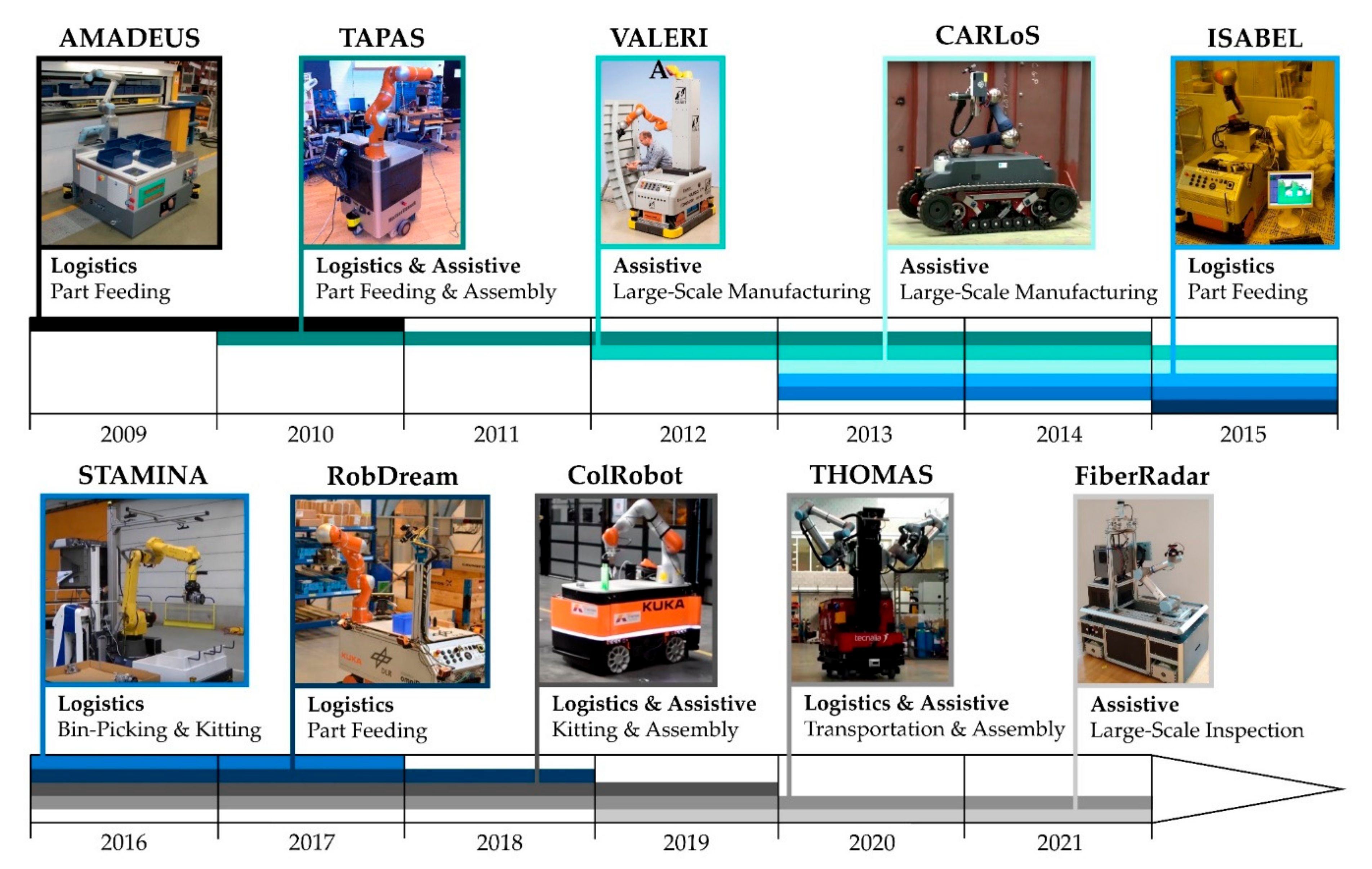
1. Introduction
Safety and Complexity in the Domain of AIMMs
- It contains a collection of many interacting objects (software-modules and hardware-components).
- It makes use of memory or feedbacks.
- It can adapt its strategies based on stored data or feedback.
- It is influenced by its environment.
- It can adapt to its environment.
- The relations between the objects and the relation between the system and the environment is non-linear and non-trivial.
2. Robot Design
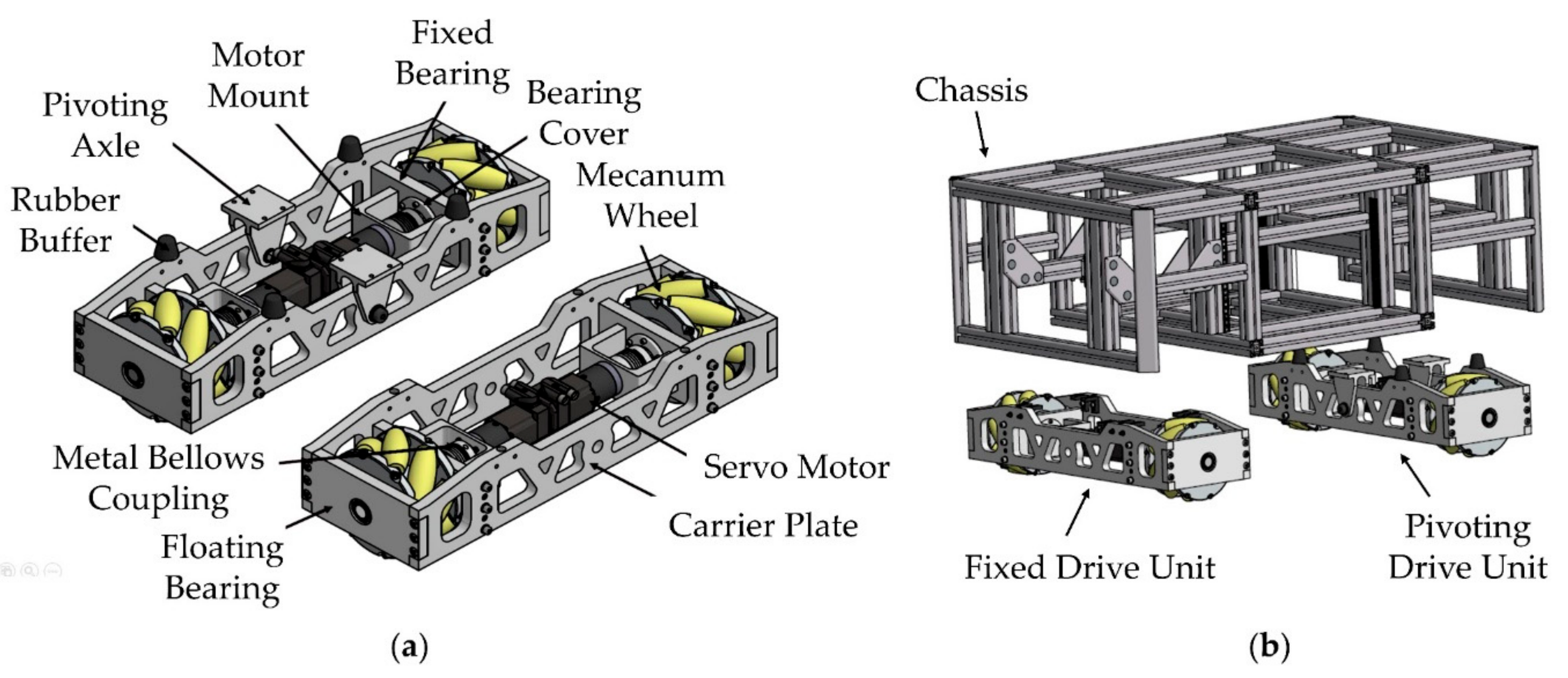
2.1. Mobile Platform
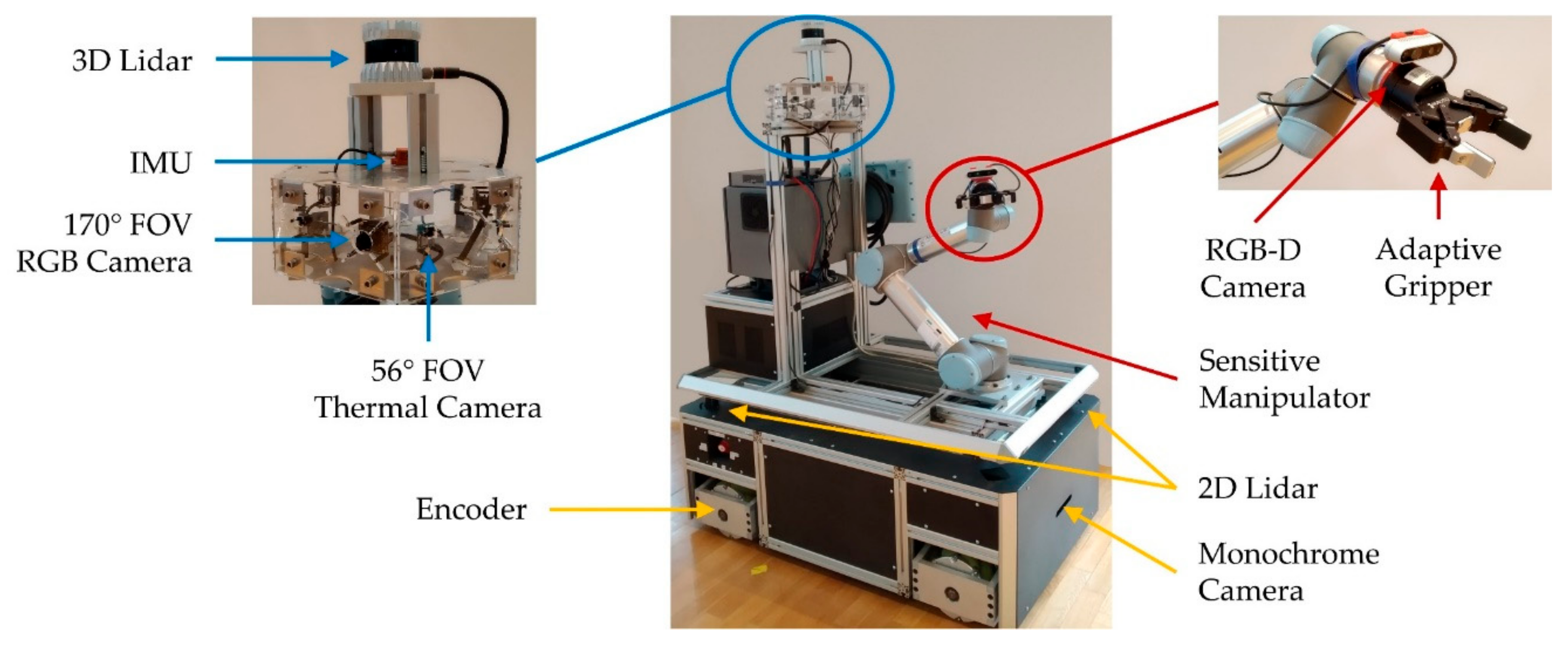
2.2. Sensor Concept
- two 2D Lidar (Sick TIM-S),
- one 3D Lidar (ouster OS0-32),
- one RGB-D camera (Intel-RealSense 435),
- three RGB cameras (ELP USBFHD04H-L170),
- one monochrome camera (UI-3251LE),
- six thermal cameras (Flir Lepton),
- one inertial measurement unit (IMU) (Xsens MTi-10) and
- four encoders.
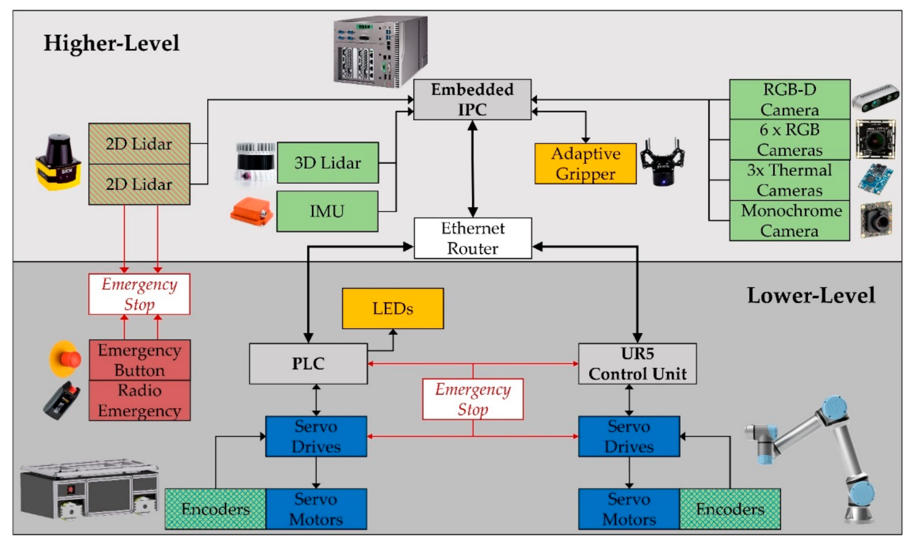
3. Control System
3.1. Components and Connections
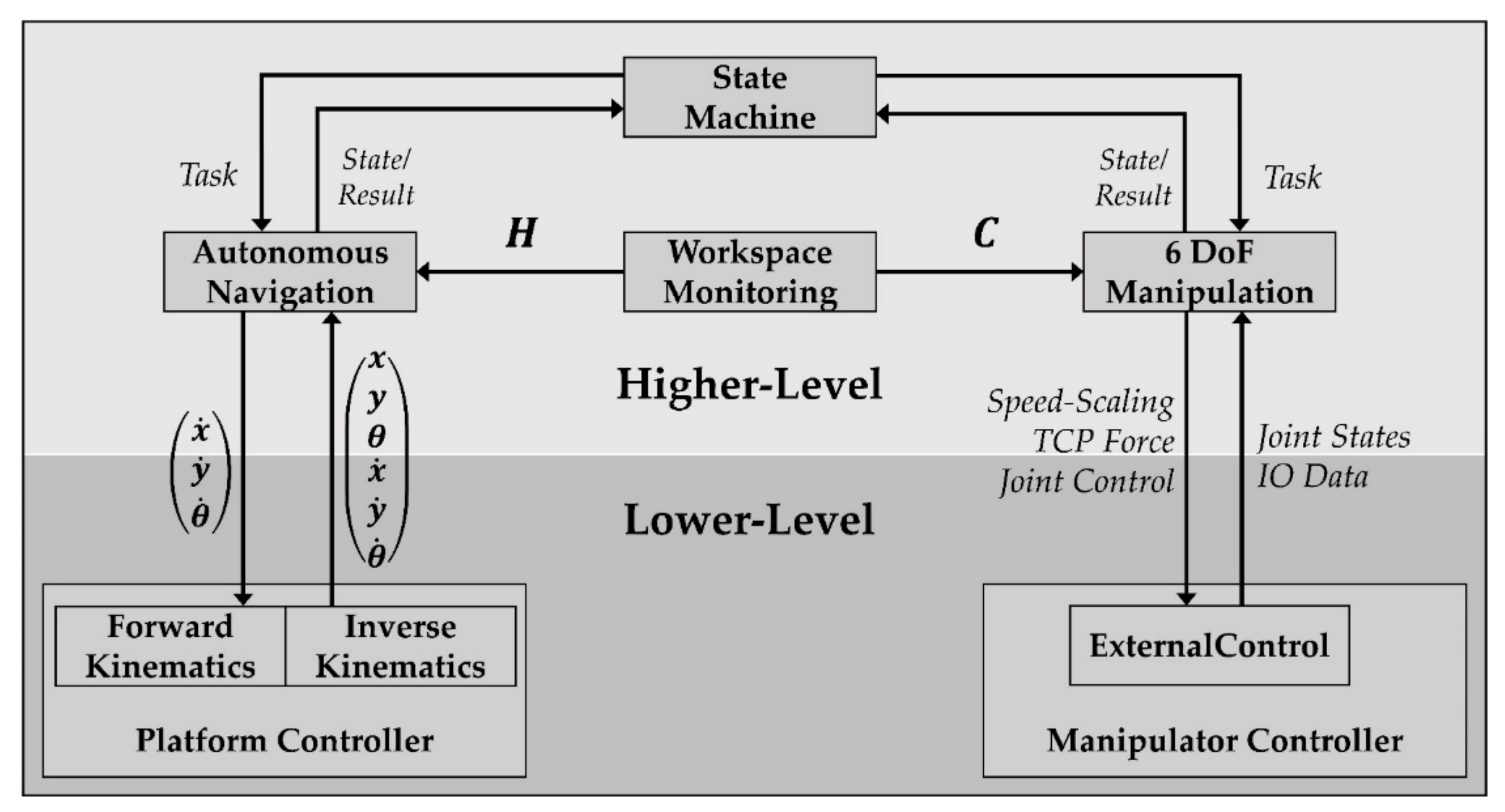
3.2. Software Architecture
- three-dimensional 360° workspace monitoring,
- autonomous navigation in unstructured dynamic environments,
- 6 Degree of Freedom (DoF) adaptive manipulation and
- task management in form of a state machine.
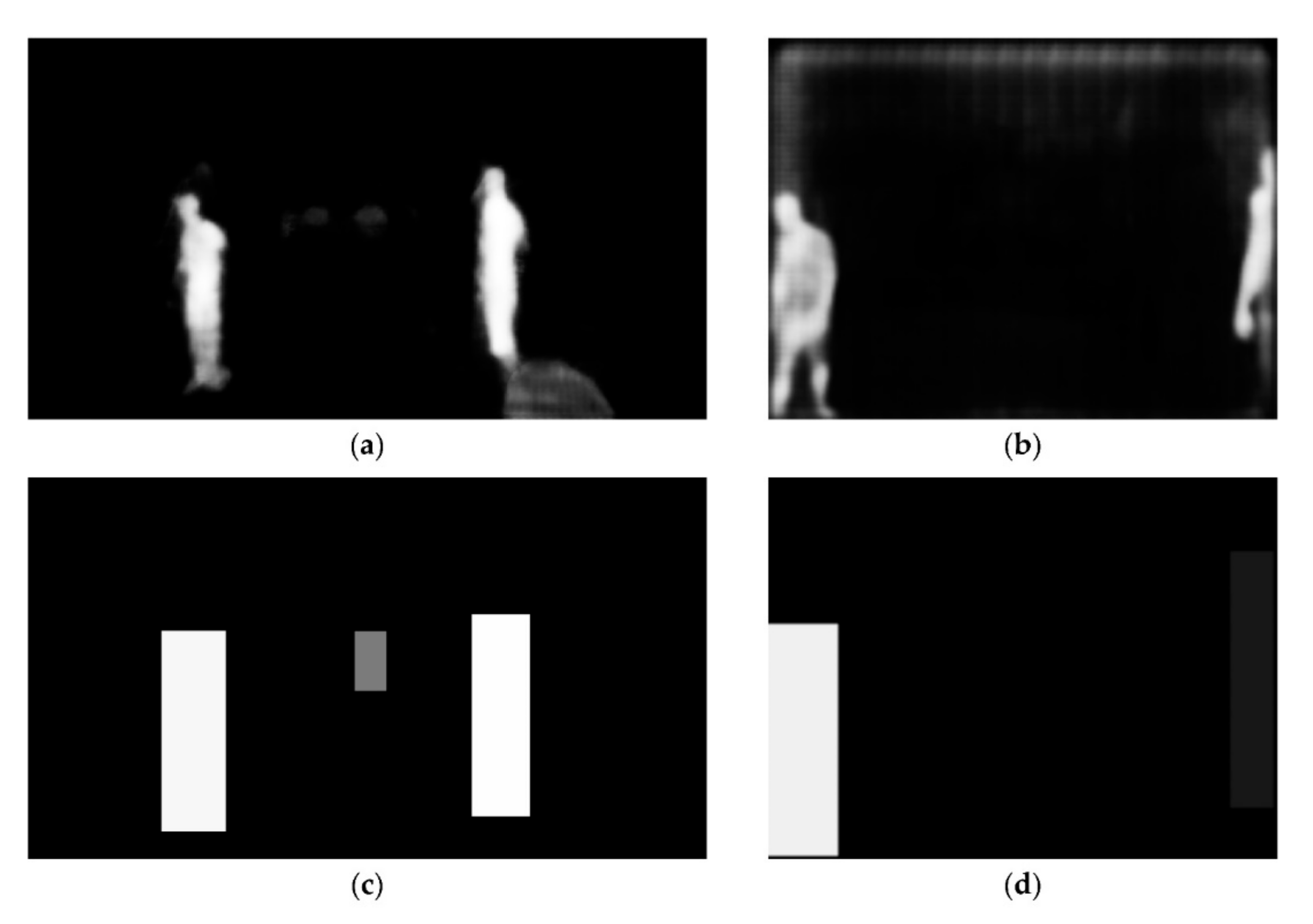
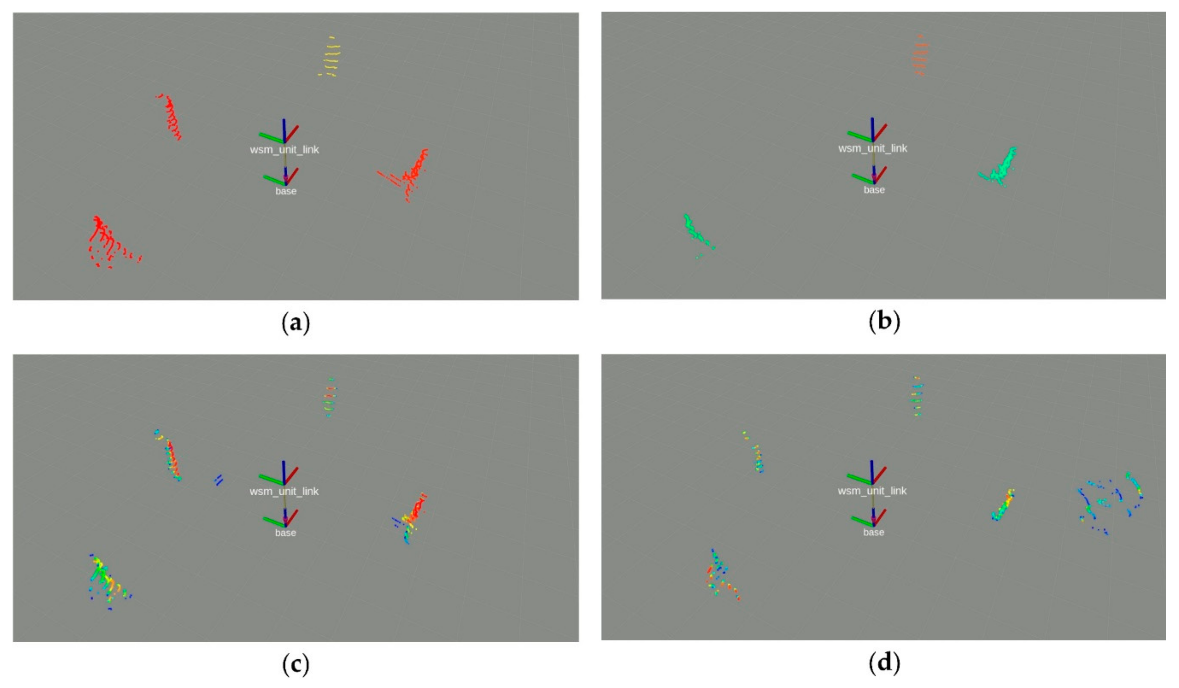
3.3. Workspace Monitoring System
- Step 1: Parallel detection and segmentation of human co-workers in RGB and thermal images.
- Step 2: Determining the corresponding 2D heatmaps in the robot coordinate system .
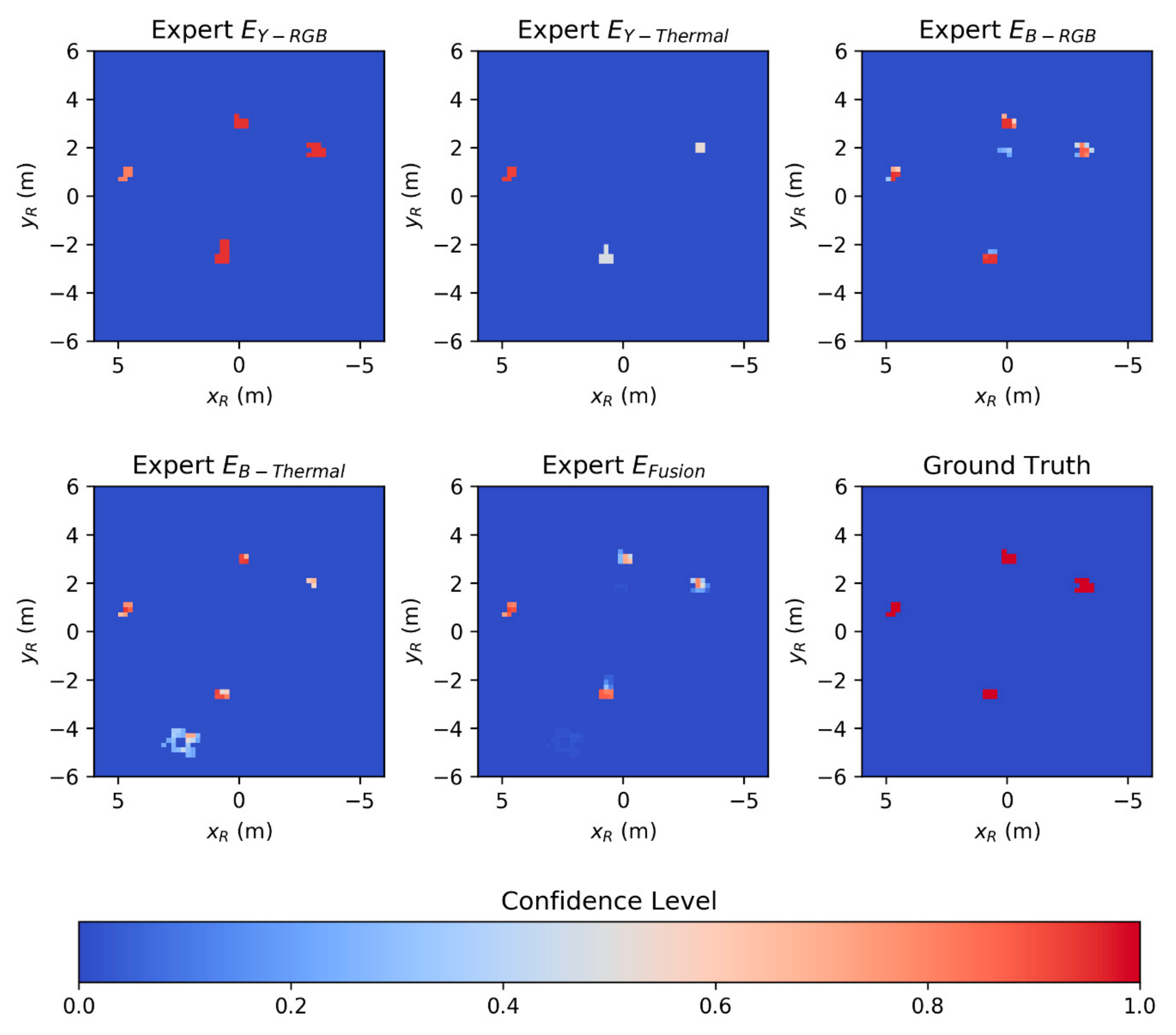
- Step 3: Fusing of the resulting position information based on the classification confidence levels.
- Bounding-box-based detection of the images .
- Bounding-box-based detection of the images .
- Segmentation-based detection of the images .
- Segmentation-based detection of the images .
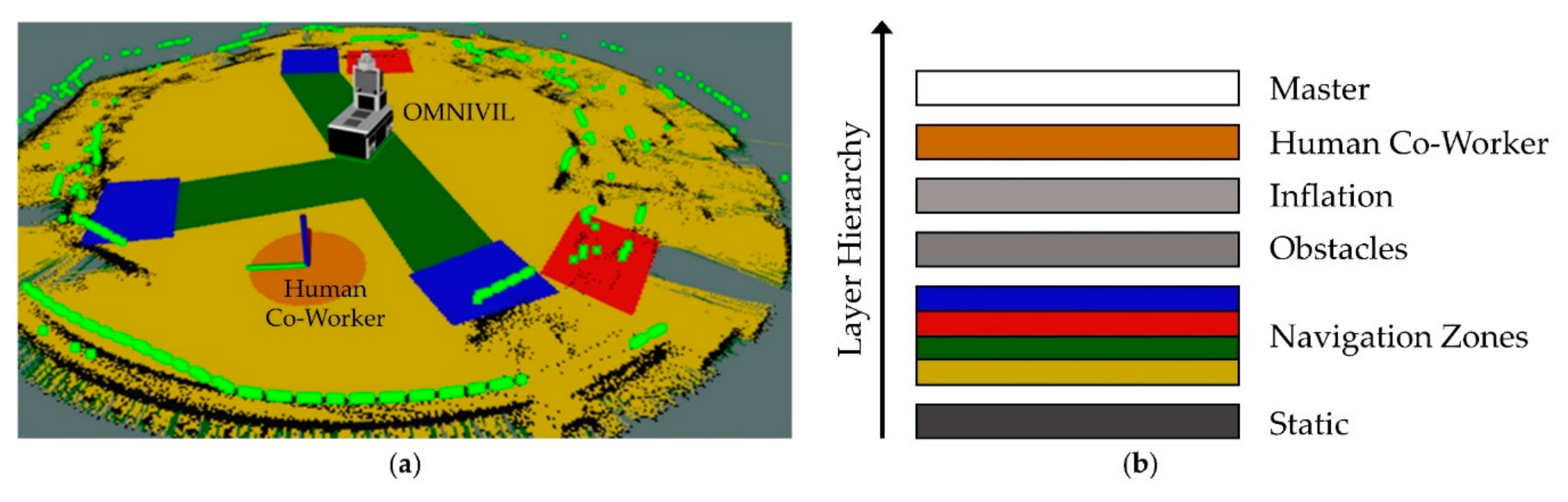
3.4. Autonomous Navigation
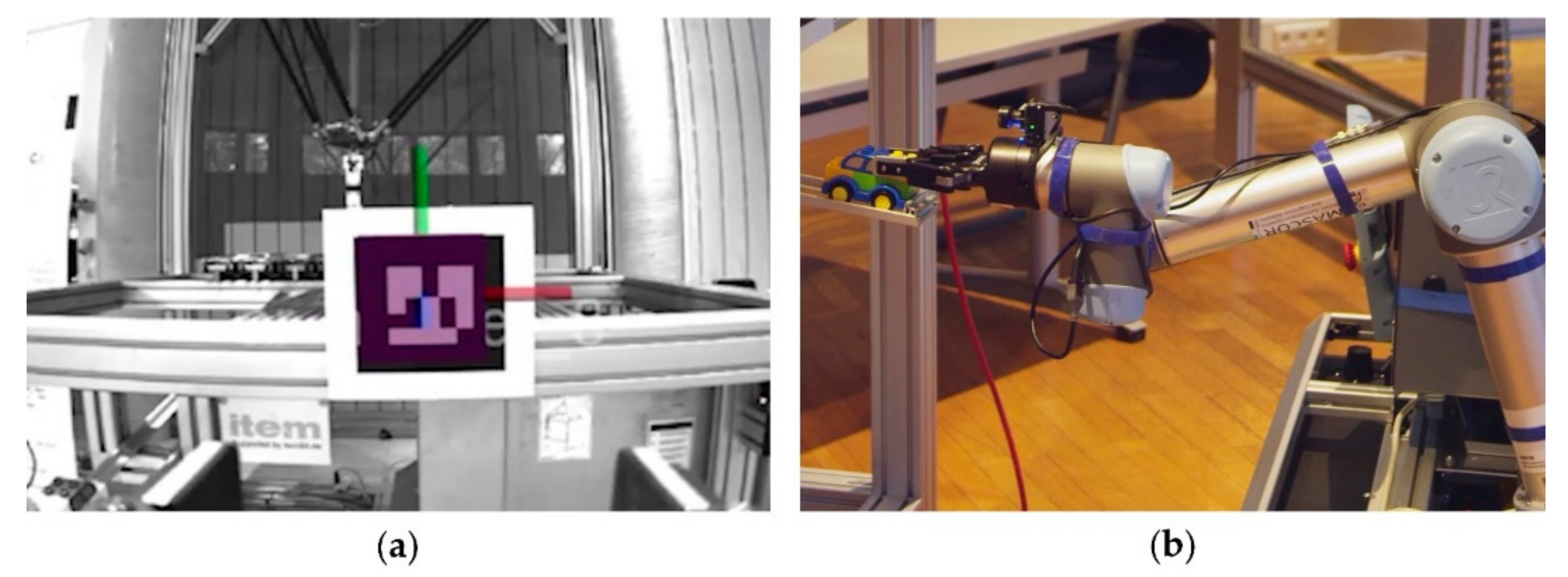
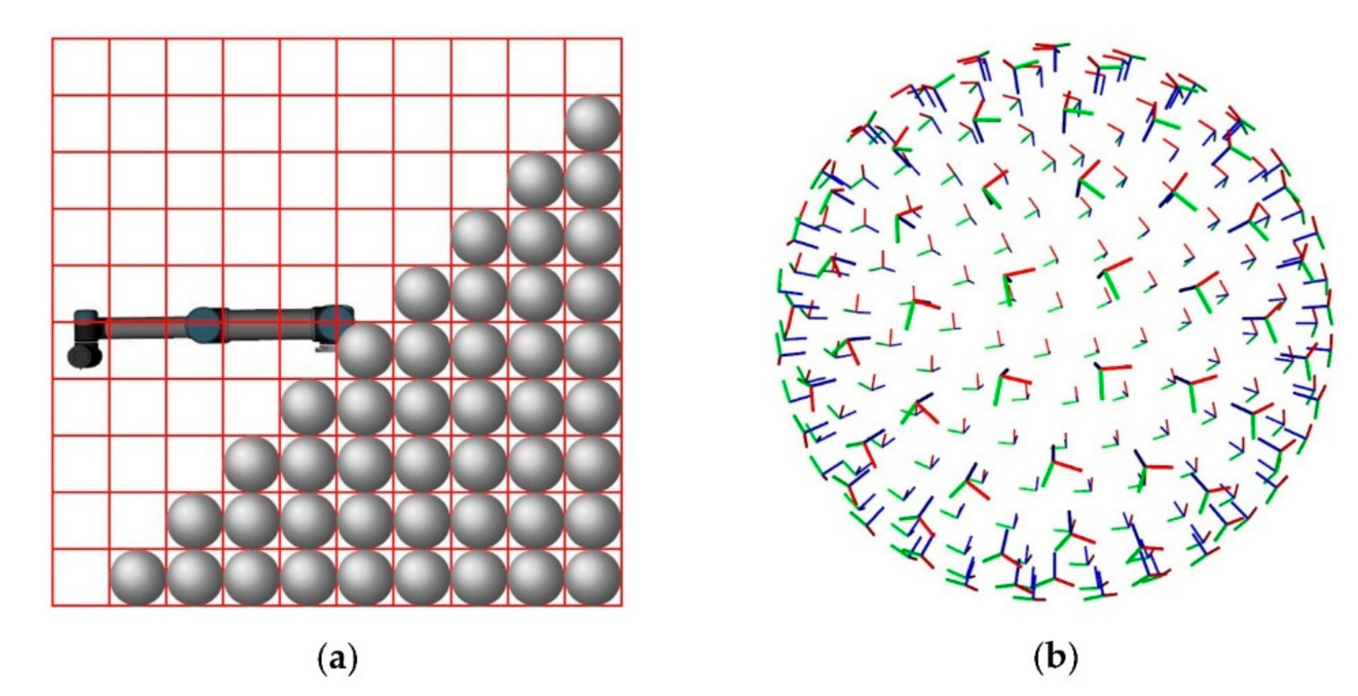
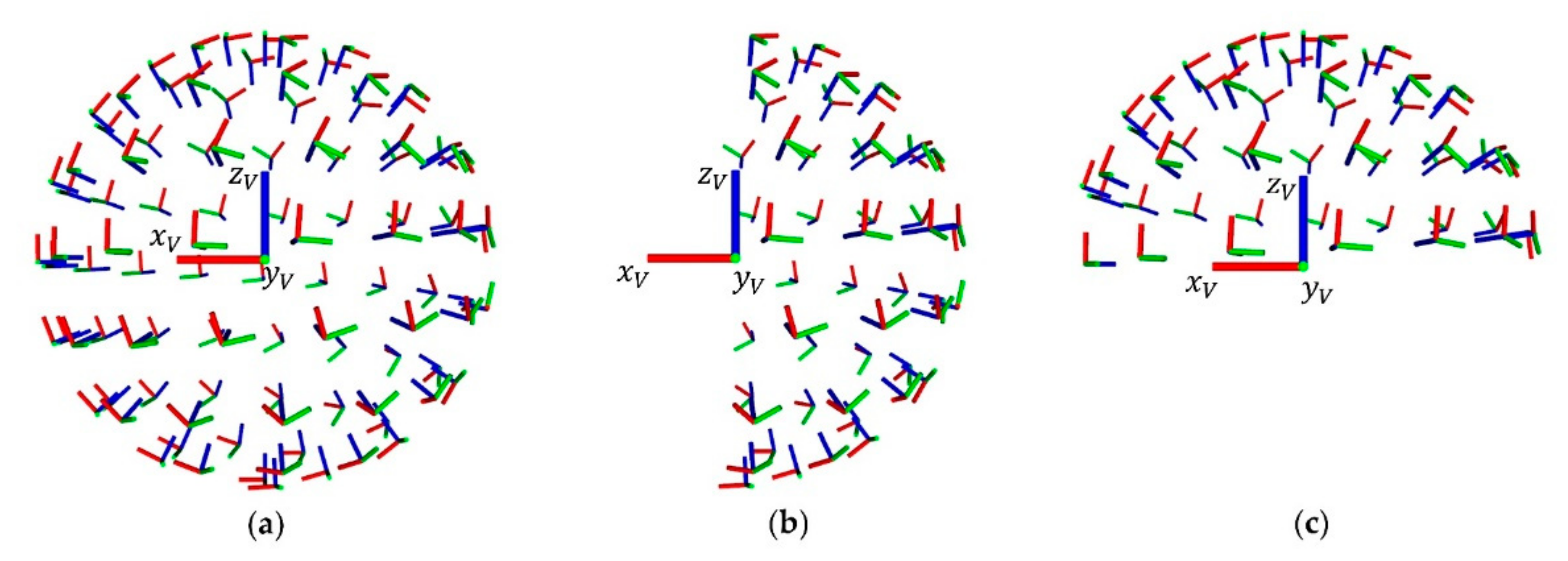
3.5. Adaptive Manipulation
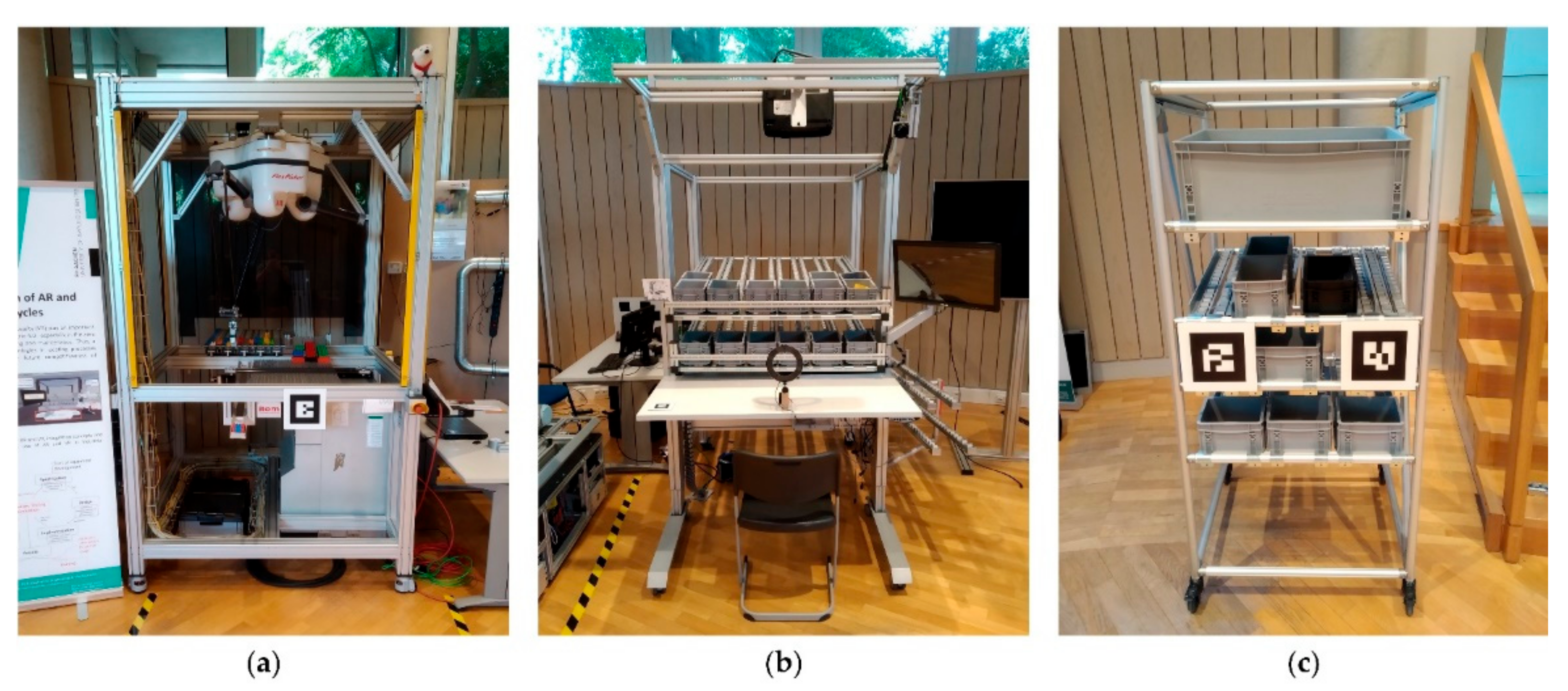
3.6. Integration in a Model Factory
4. Experiments and Discussion
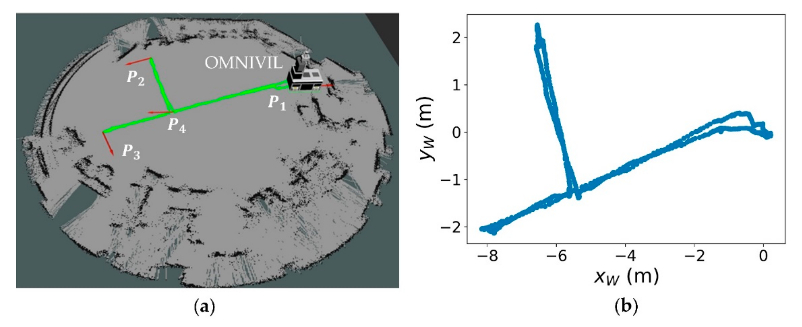
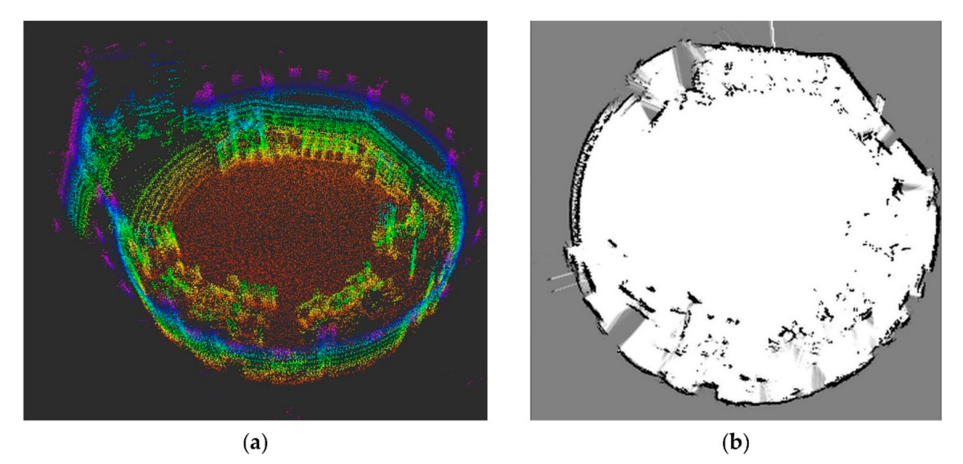
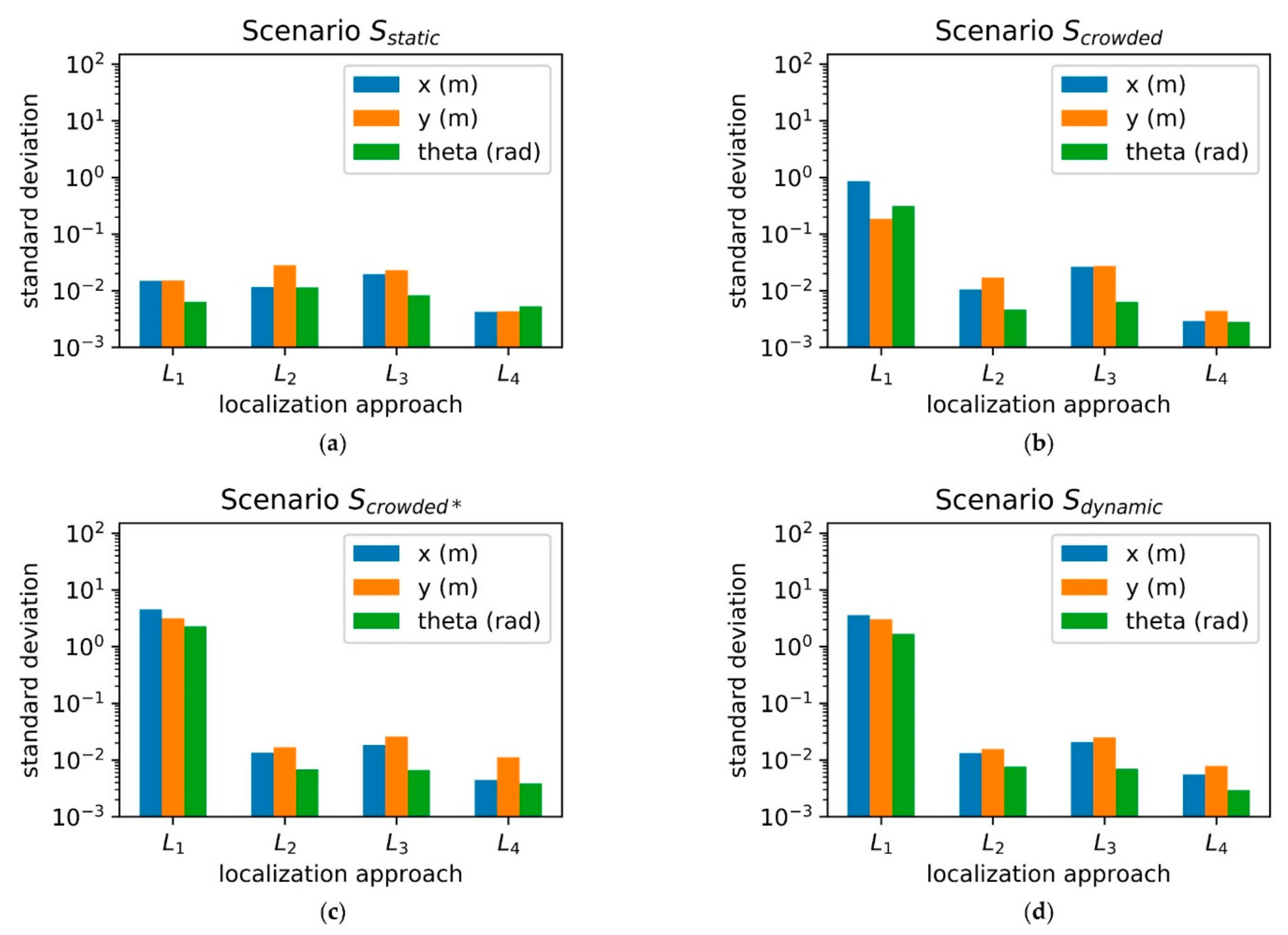
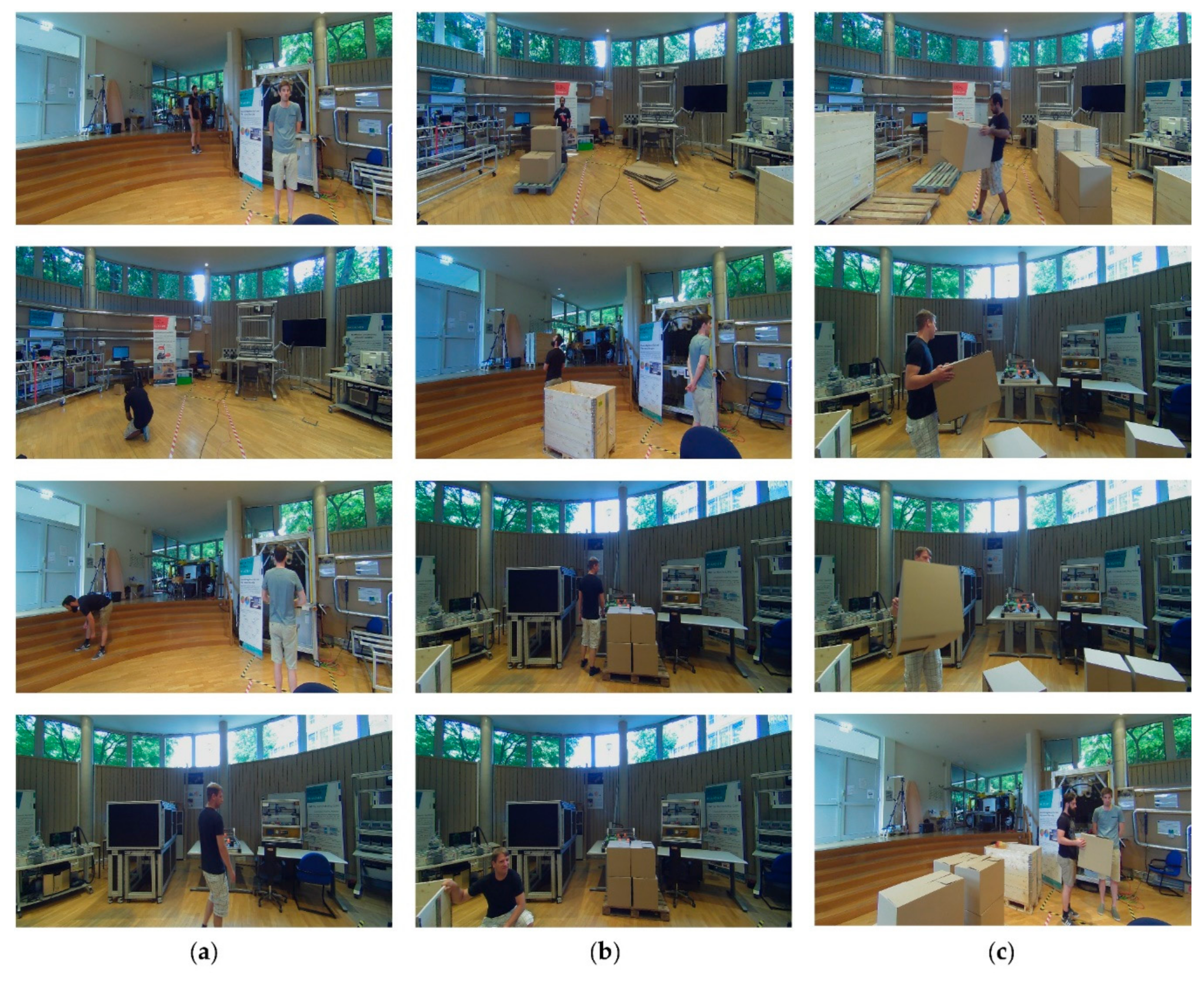
4.1. Localization and Positioning Accuracy
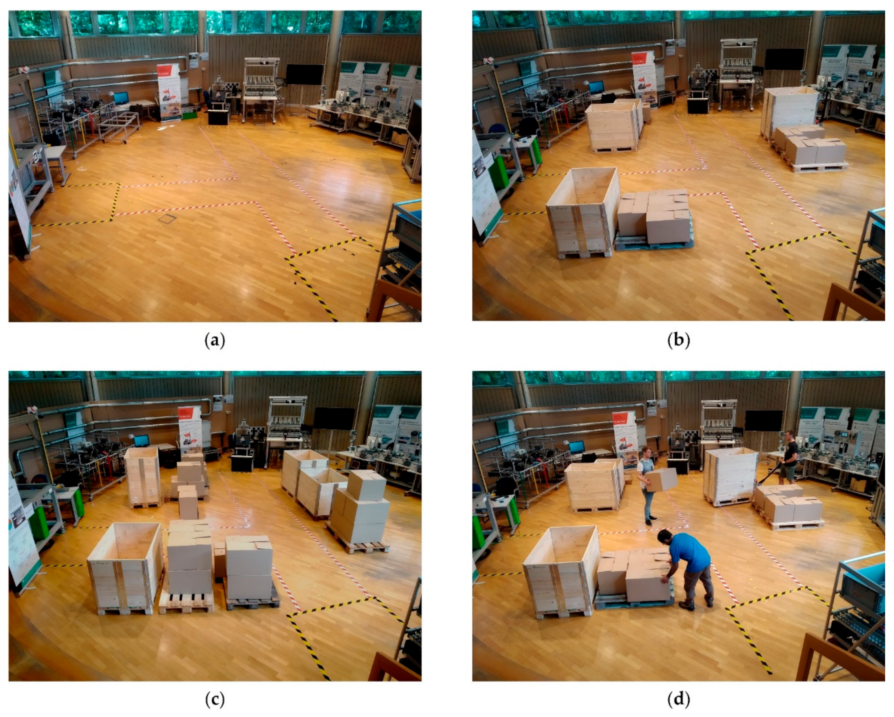
- : No changes compared to the prior generated map (see Figure 16a).
- : Minor static changes compared to the prior generated map (see Figure 16b).
- : Many static changes compared to the prior generated map (see Figure 16c).
- : This scenario is based on but includes dynamic changes. Three human co-workers are continuously transporting boxes and pallets with help of a manual lift truck (see Figure 16d).
- 2D Adaptive Monte Carlo localization (AMCL) [80].
4.2. Human Co-Worker Detection
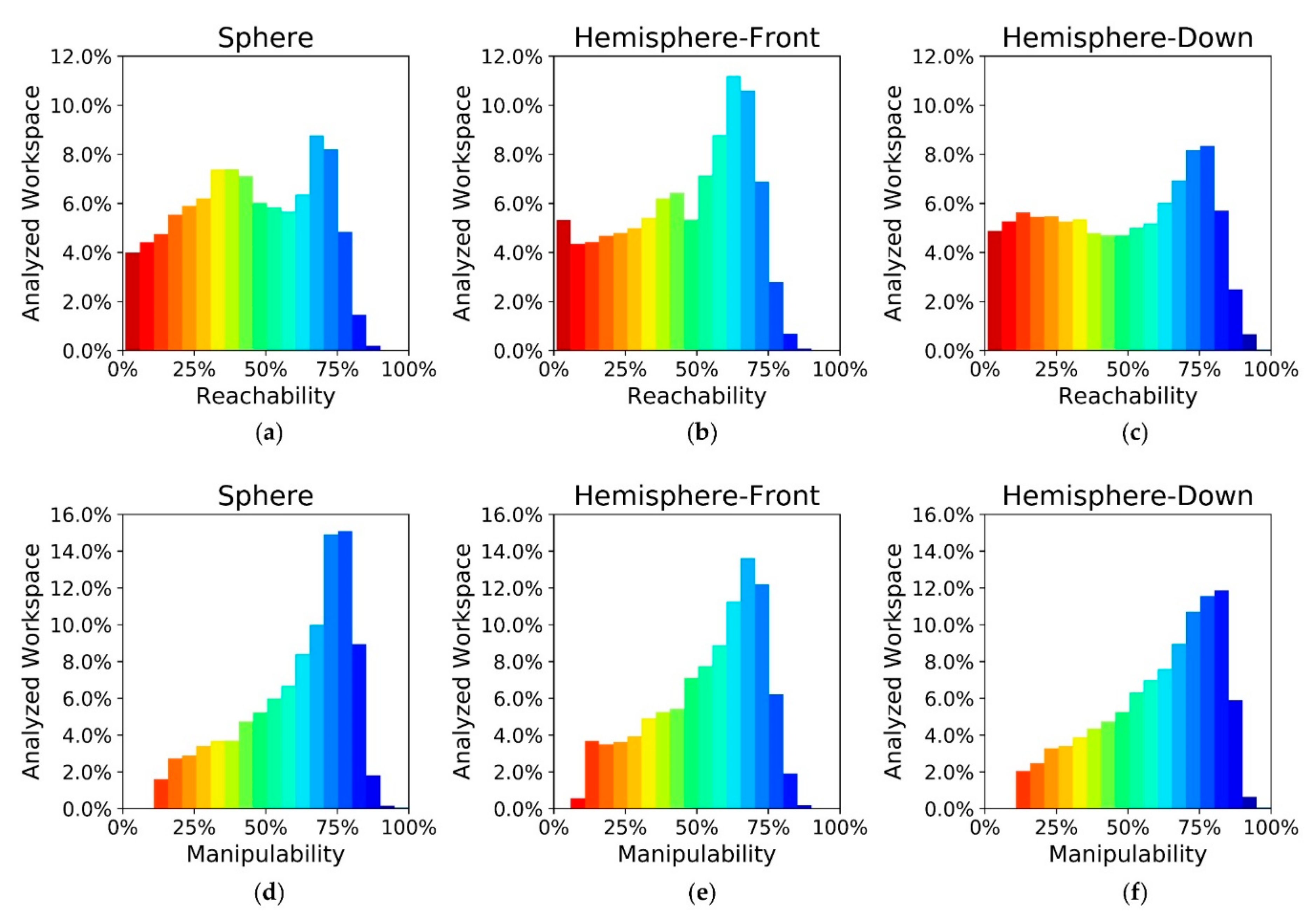
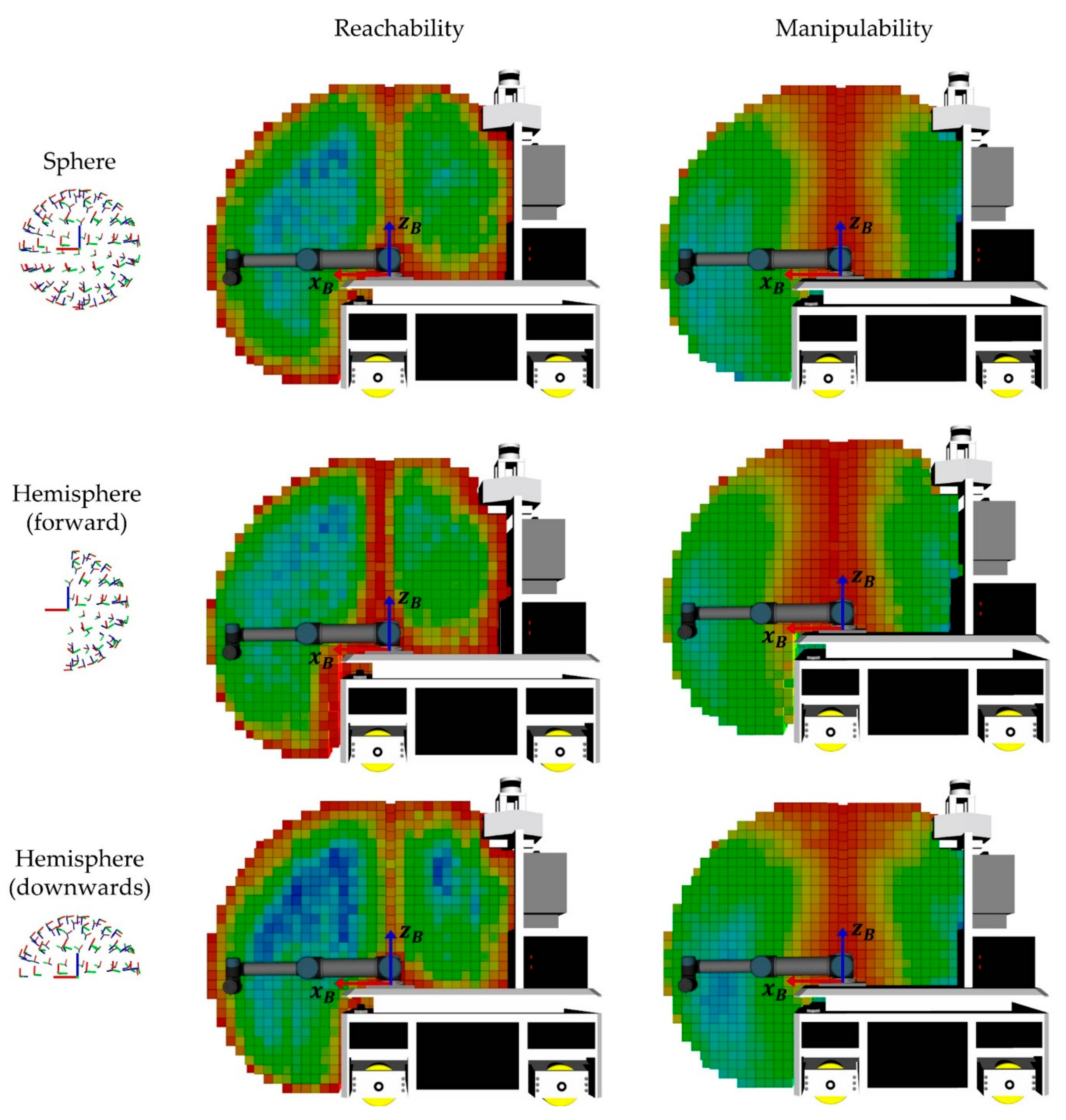
4.3. Workspace Analyzing
4.4. Comparsion with Existing Mobile Manipulators
5. Conclusions
Author Contributions
Funding
Acknowledgments
Conflicts of Interest
References
- Mishra, R.; Pundir, A.K.; Ganapathy, L. Manufacturing flexibility research: A review of literature and agenda for future research. Glob. J. Flex. Syst. Manag. 2014, 15, 101–112. [Google Scholar] [CrossRef]
- Asadi, N.; Fundin, A.; Jackson, M. The essential constituents of flexible assembly systems: A case study in the heavy vehicle manufacturing industry. Glob. J. Flex. Syst. Manag. 2015, 16, 235–250. [Google Scholar] [CrossRef]
- Pedersen, M.R.; Nalpantidis, L.; Bobick, A.; Krüger, V. On the integration of hardware-abstracted robot skills for use in industrial scenarios. In Proceedings of the International Conference on Robots and Systems, Workshop on Cognitive Robotics and Systems: Replicating Human Actions and Activities, Tokyo, Japan, 3–7 November 2013; IEEE: Piscataway, NJ, USA, 2013. [Google Scholar]
- Hasan, K.M.; Al Mamun, A. Implementation of autonomous line follower robot. In Proceedings of the International Conference on Informatics, Electronics & Vision, Dhaka, Bangladesh, 18–19 May 2012; pp. 865–869. [Google Scholar]
- Herrero-Pérez, D.; Alcaraz-Jiménez, J.J.; Martínez-Barberá, H. An accurate and robust flexible guidance system for indoor industrial environments. Int. J. Adv. Robot. Syst. 2013, 10, 292–302. [Google Scholar] [CrossRef]
- Yoon, S.W.; Park, S.-B.; Kim, J.S. Kalman filter sensor fusion for Mecanum wheeled automated guided vehicle localization. J. Sens. 2015, 2015, 347379. [Google Scholar] [CrossRef]
- Hvilshøj, M.; Bøgh, S.; Nielsen, O.S.; Madsen, O. Autonomous industrial mobile manipulation (AIMM): Past, present and future. Ind. Robot Int. J. 2012, 39, 120–135. [Google Scholar] [CrossRef]
- Schuler, J. Integration von Förder-und Handhabungseinrichtungen; Springer: Berlin, Germany, 1987. [Google Scholar]
- TAPAS. Robotics-Enabled Logistics and Assistive Services for the Transformable Factory of the Future. Available online: https://cordis.europa.eu/project/id/260026 (accessed on 11 December 2020).
- Hvilshøj, M.; Bøgh, S. “Little Helper”—An Autonomous Industrial Mobile Manipulator Concept. Int. J. Adv. Robot. Syst. 2011, 8, 80–90. [Google Scholar] [CrossRef]
- Hvilshøj, M.; Bøgh, S.; Nielsen, O.S.; Madsen, O. Multiple part feeding–real-world application for mobile manipulators. Assem. Autom. 2012, 32, 62–71. [Google Scholar] [CrossRef]
- Bogh, S.; Schou, C.; Ruehr, T.; Kogan, Y.; Doemel, A.; Brucker, M.; Eberst, C.; Tornese, R.; Sprunk, C.; Tipaldi, G.D.; et al. Integration and Assessment of Multiple Mobile Manipulators in a Real-World Industrial Production Facility. In Proceedings of the 41st International Symposium on Robotics, Munich, Germany, 2–3 June 2014; VDE: Berlin, Germany, 2014; pp. 1–8. [Google Scholar]
- Halt, L.; Meßmer, F.; Hermann, M.; Wochinger, T.; Naumann, M.; Verl, A. AMADEUS-A robotic multipurpose solution for intralogistics. In ROBOTIK 2012 7th German Conference on Robotics, Munich, Germany, 21–22 May 2012; VDE: Berlin, Germany, 2012; pp. 1–6. [Google Scholar]
- ISABEL. Innovativer Serviceroboter mit Autonomie und Intuitiver Bedienung für Effiziente Handhabung und Logistik. Available online: http://www.projekt-isabel.de/ (accessed on 11 December 2020).
- Hermann, A.; Drews, F.; Bauer, J.; Klemm, S.; Roennau, A.; Dillmann, R. Unified GPU voxel collision detection for mobile manipulation planning. In Proceedings of the International Conference on Intelligent Robots and Systems, Chicago, IL, USA, 14–18 September 2014; pp. 4154–4160. [Google Scholar]
- Hermann, A.; Mauch, F.; Fischnaller, K.; Klemm, S.; Roennau, A.; Dillmann, R. Anticipate your surroundings: Predictive collision detection between dynamic obstacles and planned robot trajectories on the GPU. In Proceedings of the European Conference on Mobile Robots, Lincoln, UK, 2–4 September 2015; pp. 1–8. [Google Scholar]
- STAMINA. Sustainable and Reliable Robotics for Part Handling in Manufacturing Automation. Available online: https://cordis.europa.eu/project/id/610917 (accessed on 11 December 2020).
- Krueger, V.; Chazoule, A.; Crosby, M.; Lasnier, A.; Pedersen, M.R.; Rovida, F.; Nalpantidis, L.; Petrick, R.; Toscano, C.; Veiga, G. A Vertical and Cyber–Physical Integration of Cognitive Robots in Manufacturing. Proc. IEEE 2016, 104, 1114–1127. [Google Scholar] [CrossRef]
- Rofalis, N.; Nalpantidis, L.; Andersen, N.A.; Krüger, V. Vision-based robotic system for object agnostic placing operations. In Proceedings of the International Conference on Computer Vision Theory and Applications, Rome, Italy, 27–29 February 2016; pp. 465–473. [Google Scholar]
- VALERI: Validation of Advanced, Collaborative Robotics for Industrial Applications. Available online: https://cordis.europa.eu/project/id/314774 (accessed on 11 December 2020).
- CARLoS. CooperAtive Robot for Large Spaces Manufacturing. Available online: https://cordis.europa.eu/article/id/165133-a-robot-coworker-inside-shipyards (accessed on 11 December 2020).
- Saenz, J.; Vogel, C.; Penzlin, F.; Elkmann, N. Safeguarding Collaborative Mobile Manipulators-Evaluation of the VALERI Workspace Monitoring System. Procedia Manuf. 2017, 11, 47–54. [Google Scholar] [CrossRef]
- Fritzsche, M.; Saenz, J.; Penzlin, F. A large scale tactile sensor for safe mobile robot manipulation. In Proceedings of the 11th International Conference on Human-Robot Interaction (HRI), Christchurch, New Zealand, 7–10 March 2016; pp. 427–428. [Google Scholar]
- Saenz, J.; Fritsche, M. Tactile sensors for safety and interaction with the mobile manipulator VALERI. In Proceedings of the ISR 2016: 47st International Symposium on Robotics, Munich, Germany, 21–22 June 2016; VDE: Berlin, Germany, 2016; pp. 1–7. [Google Scholar]
- Andersen, R.S.; Bøgh, S.; Moeslund, T.B.; Madsen, O. Intuitive task programming of stud welding robots for ship construction. In Proceedings of the International Conference on Industrial Technology, Seville, Spain, 17–19 March 2015; IEEE: Piscataway, NJ, USA, 2015; pp. 3302–3307. [Google Scholar]
- RobDream. Optimising Robot Performance while Dreaming. Available online: https://cordis.europa.eu/project/id/645403 (accessed on 11 December 2020).
- Dömel, A.; Kriegel, S.; Kaßecker, M.; Brucker, M.; Bodenmüller, T.; Suppa, M. Toward fully autonomous mobile manipulation for industrial environments. Int. J. Adv. Robot. Syst. 2017, 14, 1–19. [Google Scholar] [CrossRef]
- ColRobot. Collaborative Robotics for Assembly and Kitting in Smart Manufacturing. Available online: https://cordis.europa.eu/project/id/688807 (accessed on 11 December 2020).
- Costa, C.M.; Sousa, A.; Veiga, G. Pose Invariant Object Recognition Using a Bag of Words Approach. In Proceedings of the 3rd Iberian Robotics Conference, Seville, Spain, 22–24 November 2017; Springer: Berlin/Heidelberg, Germany, 2017; pp. 153–164. [Google Scholar]
- Guérin, J.; Gibaru, O.; Thiery, S.; Nyiri, E. Locally optimal control under unknown dynamics with learnt cost function: Application to industrial robot positioning. J. Phys. Conf. Ser. 2017, 783, 12036. [Google Scholar] [CrossRef]
- Safeea, M.; Bearee, R.; Neto, P. End-Effector Precise Hand-Guiding for Collaborative Robots. In Proceedings of the 3rd Iberian Robotics Conference, Seville, Spain, 22–24 November 2017; Springer: Berlin/Heidelberg, Germany, 2017; pp. 595–605. [Google Scholar]
- THOMAS. Mobile Dual Arm Robotic Workers with Embedded Cognition for Hybrid and Dynamically Reconfigurable Manufacturing Systems. Available online: https://cordis.europa.eu/project/id/723616 (accessed on 11 December 2020).
- Outón, J.L.; Villaverde, I.; Herrero, H.; Esnaola, U.; Sierra, B. Innovative Mobile Manipulator Solution for Modern Flexible Manufacturing Processes. Sensors 2019, 19, 5414. [Google Scholar] [CrossRef]
- Kousi, N.; Michalos, G.; Aivaliotis, S.; Makris, S. An outlook on future assembly systems introducing robotic mobile dual arm workers. Procedia CIRP 2018, 72, 33–38. [Google Scholar] [CrossRef]
- Kousi, N.; Stoubos, C.; Gkournelos, C.; Michalos, G.; Makris, S. Enabling Human Robot Interaction in flexible robotic assembly lines: An Augmented Reality based software suite. Procedia CIRP 2019, 81, 1429–1434. [Google Scholar] [CrossRef]
- FiberRadar. Available online: https://www.fh-aachen.de/iaam/autonome-mobile-systeme/fiberradar/#c168389 (accessed on 5 November 2020).
- OPC Foundation. Unified Architecture. Available online: https://opcfoundation.org/about/opc-technologies/opc-ua/ (accessed on 23 July 2020).
- Bøgh, S.; Hvilshøj, M.; Kristiansen, M.; Madsen, O. Identifying and evaluating suitable tasks for autonomous industrial mobile manipulators (AIMM). Int. J. Adv. Manuf. Technol. 2012, 61, 713–726. [Google Scholar] [CrossRef]
- Madsen, O.; Bøgh, S.; Schou, C.; Andersen, R.S.; Damgaard, J.S.; Pedersen, M.R.; Krüger, V. Integration of mobile manipulators in an industrial production. Ind. Robot Int. J. Robot. Res. Appl. 2015, 42, 11–18. [Google Scholar] [CrossRef]
- Fechter, M.; Foith-Förster, P.; Pfeiffer, M.S.; Bauernhansl, T. Axiomatic Design Approach for Human-robot Collaboration in Flexibly Linked Assembly Layouts. Procedia CIRP 2016, 50, 629–634. [Google Scholar] [CrossRef]
- Wang, L.; Gao, R.; Váncza, J.; Krüger, J.; Wang, X.V.; Makris, S.; Chryssolouris, G. Symbiotic human-robot collaborative assembly. CIRP Ann. 2019, 68, 701–726. [Google Scholar] [CrossRef]
- Saenz, J.; Elkmann, N.; Gibaru, O.; Neto, P. Survey of methods for design of collaborative robotics applications-why safety is a barrier to more widespread robotics uptake. In Proceedings of the 4th International Conference on Mechatronics and Robotics Engineering, Valenciennes, France, 7–11 February 2018; pp. 95–101. [Google Scholar]
- Bexten, S.; Scholle, J.; Saenz, J.; Walter, C.; Elkmann, N. Validation of workspace monitoring and human detection for soft safety with collaborative mobile manipulator using machine learning techniques in the ColRobot project. In Proceedings of the 50th International Symposium on Robotics, Munich, Germany, 20–21 June 2018; pp. 191–198. [Google Scholar]
- Lasota, P.A.; Fong, T.; Shah, J.A. A survey of methods for safe human-robot interaction. Found. Trends Robot. 2017, 5, 261–349. [Google Scholar] [CrossRef]
- Sheridan, T.B. Humans and Automation: System Design and Research Issues; John Wiley & Sons: New York, NY, USA, 2002. [Google Scholar]
- Johnson, N. Simply Complexity: A Clear Guide to Complexity Theory; Oneworld Publications: London, UK, 2009. [Google Scholar]
- Gell-Mann, M. What Is Complexity? Complexity and Industrial Clusters; Springer: Berlin/Heidelberg, Germany, 2002; pp. 13–24. [Google Scholar]
- Diegel, O.; Badve, A.; Bright, G.; Potgieter, J.; Tlale, S. Improved mecanum wheel design for omni-directional robots. In Proceedings of the Australasian Conference on Robotics and Automation, Auckland, New Zealand, 27–29 November 2002; pp. 117–121. [Google Scholar]
- Qian, J.; Zi, B.; Wang, D.; Ma, Y.; Zhang, D. The Design and Development of an Omni-Directional Mobile Robot Oriented to an Intelligent Manufacturing System. Sensors 2017, 17, 2073. [Google Scholar] [CrossRef]
- Quigley, M.; Conley, K.; Gerkey, B.; Faust, J.; Foote, T.; Leibs, J.; Wheeler, R.; Ng, A.Y. ROS: An open-source Robot Operating System. In Proceedings of the Workshops at the IEEE International Conference on Robotics and Automation, Kobe, Japan, 12–17 May 2009; p. 5. [Google Scholar]
- Indiveri, G. Swedish wheeled omnidirectional mobile robots: Kinematics analysis and control. IEEE Trans. Robot. 2009, 25, 164–171. [Google Scholar] [CrossRef]
- Redmon, J.; Farhadi, A. Yolov3: An incremental improvement. arXiv 2018, arXiv:1804.02767. [Google Scholar]
- Lin, T.-Y.; Maire, M.; Belongie, S.; Hays, J.; Perona, P.; Ramanan, D.; Dollár, P.; Zitnick, C.L. Microsoft coco: Common objects in context. In Proceedings of the 13th European Conference on Computer Vision, Zurich, Switzerland, 6–12 September 2014; Springer: Berlin/Heidelberg, Germany, 2014; pp. 740–755. [Google Scholar]
- FLIR. ADAS Dataset. Available online: https://www.flir.com/oem/adas/adas-dataset-form/ (accessed on 21 September 2020).
- Milioto, A.; Mandtler, L.; Stachniss, C. Fast Instance and Semantic Segmentation Exploiting Local Connectivity, Metric Learning, and One-Shot Detection for Robotics. In Proceedings of the International Conference on Robotics and Automation, Montreal, QC, Canada, 20–24 May 2019; IEEE: Piscataway, NJ, USA, 2019; pp. 5481–5487. [Google Scholar]
- Milioto, A.; Stachniss, C. Bonnet: An open-source training and deployment framework for semantic segmentation in robotics using cnns. In Proceedings of the International Conference on Robotics and Automation, Montreal, QC, Canada, 20–24 May 2019; IEEE: Piscataway, NJ, USA, 2019; pp. 7094–7100. [Google Scholar]
- St-Charles, P.-L.; Bilodeau, G.-A.; Bergevin, R. Online mutual foreground segmentation for multispectral stereo videos. Int. J. Comput. Vis. 2019, 127, 1044–1062. [Google Scholar] [CrossRef]
- Dhall, A.; Chelani, K.; Radhakrishnan, V.; Krishna, K.M. LiDAR-camera calibration using 3D-3D point correspondences. arXiv 2017, arXiv:1705.09785. [Google Scholar]
- Hinton, G.E. Products of experts. J. Environ. Radioact. 1999, 44, 1–19. [Google Scholar] [CrossRef]
- Genest, C.; Zidek, J.V. Combining probability distributions: A critique and an annotated bibliography. Stat. Sci. 1986, 1, 114–135. [Google Scholar] [CrossRef]
- Satopää, V.A.; Baron, J.; Foster, D.P.; Mellers, B.A.; Tetlock, P.E.; Ungar, L.H. Combining multiple probability predictions using a simple logit model. Int. J. Forecast. 2014, 30, 344–356. [Google Scholar] [CrossRef]
- Lu, D.V.; Hershberger, D.; Smart, W.D. Layered costmaps for context-sensitive navigation. In Proceedings of the International Conference on Intelligent Robots and Systems, Chicago, IL, USA, 14–18 September 2014; IEEE: Piscataway, NJ, USA, 2014; pp. 709–715. [Google Scholar]
- Kalman, R.E. A New Approach to Linear Filtering and Prediction Problems. Trans. ASME J. Basic Eng. 1960, 82, 35–45. [Google Scholar] [CrossRef]
- Moore, T.; Stouch, D. A generalized extended kalman filter implementation for the robot operating system. In Proceedings of the 13th International Conference on Intelligent Autonomous Systems, Padua, Italy, 15–19 July 2016; Springer: Berlin/Heidelberg, Germany, 2016; pp. 335–348. [Google Scholar]
- Hess, W.; Kohler, D.; Rapp, H.; Andor, D. Real-time loop closure in 2D LIDAR SLAM. In Proceedings of the International Conference on Robotics and Automation, Stockholm, Sweden, 16–21 May 2016; IEEE: Piscataway, NJ, USA, 2016; pp. 1271–1278. [Google Scholar]
- Agarwal, S.; Mierle, K. Ceres Solver. Available online: http://ceres-solver.org/ (accessed on 2 September 2020).
- Hart, P.; Nilsson, N.; Raphael, B. A Formal Basis for the Heuristic Determination of Minimum Cost Paths. IEEE Trans. Syst. Sci. Cybern. 1968, 4, 100–107. [Google Scholar] [CrossRef]
- Dijkstra, E.W. A note on two problems in connexion with graphs. Numer. Math. 1959, 1, 269–271. [Google Scholar] [CrossRef]
- Sucan, I.A.; Chitta, S. MoveIt! Available online: http://moveit.ros.org (accessed on 30 July 2020).
- Otto, K.; Ossi, A.; Mika, H. ALVAR. Available online: http://virtual.vtt.fi/virtual/proj2/multimedia/alvar/index.html (accessed on 30 July 2020).
- Kuffner, J.J.; LaValle, S.M. RRT-connect: An efficient approach to single-query path planning. In Proceedings of the International Conference on Robotics and Automation, San Francisco, CA, USA, 24–28 April 2000; IEEE: Piscataway, NJ, USA, 2000; pp. 995–1001. [Google Scholar]
- Zacharias, F.; Borst, C.; Hirzinger, G. Capturing robot workspace structure: Representing robot capabilities. In Proceedings of the International Conference on Intelligent Robots and Systems, San Diego, CA, USA, 29 October–2 November 2007; IEEE: Piscataway, NJ, USA, 2007; pp. 3229–3236. [Google Scholar]
- Saff, E.B.; Kuijlaars, A.B.J. Distributing many points on a sphere. Math. Intell. 1997, 19, 5–11. [Google Scholar] [CrossRef]
- Yoshikawa, T. Manipulability of Robotic Mechanisms. Int. J. Robot. Res. 1985, 4, 3–9. [Google Scholar] [CrossRef]
- Ulmer, J.; Braun, S.; Cheng, C.-T.; Dowey, S.; Wollert, J. Human-Centered Gamification Framework for Manufacturing Systems. Procedia CIRP 2020, 93, 670–675. [Google Scholar] [CrossRef]
- Grisetti, G.; Stachniss, C.; Burgard, W. OpenSLAM: GMapping. Available online: http://openslam.org/gmapping.html (accessed on 14 October 2020).
- Grisettiyz, G.; Stachniss, C.; Burgard, W. Improving grid-based slam with rao-blackwellized particle filters by adaptive proposals and selective resampling. In Proceedings of the International Conference on Robotics and Automation, Barcelona, Spain, 18–22 April 2005; IEEE: Piscataway, NJ, USA, 2005; pp. 2432–2437. [Google Scholar]
- Grisetti, G.; Stachniss, C.; Burgard, W. Improved Techniques for Grid Mapping With Rao-Blackwellized Particle Filters. IEEE Trans. Robot. 2007, 23, 34–46. [Google Scholar] [CrossRef]
- Shan, T.; Englot, B. Lego-loam: Lightweight and ground-optimized lidar odometry and mapping on variable terrain. In Proceedings of the International Conference on Intelligent Robots and Systems, Madrid, Spain, 1–5 October 2018; IEEE: Piscataway, NJ, USA, 2018; pp. 4758–4765, ISBN 1538680947. [Google Scholar]
- Dellaert, F.; Fox, D.; Burgard, W.; Thrun, S. Monte carlo localization for mobile robots. In Proceedings of the International Conference on Robotics and Automation, Detroit, MI, USA, 10–15 May 1999; IEEE: Piscataway, NJ, USA, 1999; pp. 1322–1328. [Google Scholar]
- Watanabe, A.; Hatao, N.; Jomura, S.; Maekawa, D.; Koga, Y. mcl_3dl. Available online: https://github.com/at-wat/mcl_3dl (accessed on 2 September 2020).
- Thrun, S.; Burgard, W.; Fox, D. Probabilistic Robotics; MIT Press: Cambridge, MA, USA; London, UK, 2006; ISBN 9780262201629. [Google Scholar]
- Ueda, R.; Arai, T.; Sakamoto, K.; Kikuchi, T.; Kamiya, S. Expansion resetting for recovery from fatal error in monte carlo localization-comparison with sensor resetting methods. In Proceedings of the International Conference on Intelligent Robots and Systems, Sendai, Japan, 28 September–2 October; IEEE: Piscataway, NJ, USA, 2004; pp. 2481–2486, ISBN 0780384636. [Google Scholar]
- Koide, K.; Miura, J.; Menegatti, E. A portable three-dimensional LIDAR-based system for long-term and wide-area people behavior measurement. Int. J. Adv. Robot. Syst. 2019, 16, 172988141984153. [Google Scholar] [CrossRef]
- Magnusson, M.; Lilienthal, A.; Duckett, T. Scan Registration for Autonomous Mining Vehicles Using 3D-NDT: Research Articles. J. Field Robot. 2007, 24, 803–827. [Google Scholar] [CrossRef]
- Engemann, H.; Badri, S.; Wenning, M.; Kallweit, S. Implementation of an Autonomous Tool Trolley in a Production Line. In Proceedings of the International Conference on Robotics in Alpe-Adria Danube Region, Kaiserslautern, Germany, 19–21 June 2019; Springer: Berlin/Heidelberg, Germany, 2019; pp. 117–125. [Google Scholar]
- Dieber, B.; Breiling, B. Security Considerations in Modular Mobile Manipulation. In Proceedings of the International Conference on Robotic Computing, Naples, Italy, 25–27 February 2019; IEEE: Piscataway, NJ, USA, 2019; pp. 70–77. [Google Scholar]
- Unhelkar, V.V.; Dörr, S.; Bubeck, A.; Lasota, P.A.; Perez, J.; Siu, H.C.; Boerkoel, J.C., Jr.; Tyroller, Q.; Bix, J.; Bartscher, S. Introducing Mobile Robots to Moving-Floor Assembly Lines. 2018. Available online: https://workofthefuturecongress.mit.edu/wp-content/uploads/2019/06/Unhelkar_Shah_etal_RA_Magazine_2018.pdf (accessed on 10 December 2020).
- Walter, C.; Schulenberg, E.; Saenz, J.; Penzlin, F.; Elkmann, N. Demonstration of Complex Task Execution using Basic Functionalities: Experiences with the Mobile Assistance Robot, “ANNIE”. In Proceedings of the International Conference on Automated Planning and Scheduling, London, UK, 12–17 June 2016; pp. 10–16. [Google Scholar]
- Saenz, J.; Penzlin, F.; Vogel, C.; Fritzsche, M. VALERI—A Collaborative Mobile Manipulator for Aerospace Production. In Advances in Cooperative Robotics; Tokhi, M.O., Virk, G.S., Eds.; World Scientific: Singapore, 2016; pp. 186–195. ISBN 978-981-314-912-0. [Google Scholar]
- Vogel, C.; Saenz, J. Optical Workspace Monitoring System for Safeguarding Tools on the Mobile Manipulator VALERI. In Proceedings of the 47th International Symposium on Robotics, Munich, Germany, 21–22 June 2016; VDE: Berlin, Germany, 2016; pp. 1–6. [Google Scholar]
- Dean-Leon, E.; Pierce, B.; Bergner, F.; Mittendorfer, P.; Ramirez-Amaro, K.; Burger, W.; Cheng, G. TOMM: Tactile omnidirectional mobile manipulator. In Proceedings of the International Conference on Robotics and Automation, Singapore, 29 May–3 June 2017; IEEE: Piscataway, NJ, USA, 2017; pp. 2441–2447. [Google Scholar]
- KUKA. Mobile Robots from KUKA. Available online: https://www.kuka.com/en-de/products/mobility/mobile-robots (accessed on 27 November 2020).
- YASKAWA. New Paths for Mobile Robotics. Available online: https://www.motoman.com/en-us/about/blog/new-paths-for-mobile-robotics (accessed on 10 December 2020).
- Neobotix. Mobile Manipulator MM-700. Available online: https://www.neobotix-robots.com/products/mobile-manipulators/mobile-manipulator-mm-700 (accessed on 10 December 2020).
- Schlotzhauer, A.; Kaiser, L.; Brandstötter, M. Safety of Industrial Applications with Sensitive Mobile Manipulators–Hazards and Related Safety Measures. In Proceedings of the Austrian Robotics Workshop, Innsbruck, Austria, 17–18 May 2018; pp. 43–47. [Google Scholar]
- Mobile Industrial Robots. MiR100. Available online: https://www.mobile-industrial-robots.com/en/solutions/robots/mir100/ (accessed on 10 December 2020).


| Description | Value |
|---|---|
| Dimensions | 1256 × 780 × 522 mm³ (L × W × H) |
| Ground Clearance | 42 mm |
| Weight | 200 kg |
| Maximum Payload | 380 kg |
| Maximum Velocity | 1.3 m/s |
| Wheel Type | Mecanum |
| Kinematic | Holonomic |
| Scenario | Valid Beams | Change Factor A |
|---|---|---|
| 416 | 0.0 | |
| 329 | 0.388 | |
| 388 | 0.512 |
| Localization Strategy | CPU (% of Single Core) | RAM (GB) |
|---|---|---|
| (2D) | 20 | 0.51 |
| (2D) | 46 | 3.14 |
| (3D) | 103 | 2.56 |
| (3D) | 240 | 1.92 |
| Localization Strategy | Goal Pose | σx (mm) | σy (mm) | σθ (rad) |
|---|---|---|---|---|
| (workbench) | 7 | 6 | 0.004 | |
| (robot cell) | 9 | 12 | 0.007 | |
| (ware rack) | 11 | 23 | 0.012 | |
| (workbench) | 3 | 10 | 0.003 | |
| (robot cell) | 3 | 3 | 0.005 | |
| (ware rack) | 3 | 3 | 0.003 | |
| (workbench) | 9 | 5 | 0.01 | |
| (robot cell) | 5 | 10 | 0.01 | |
| (ware rack) | 10 | 12 | 0.02 |
| AP | 0.75 | 0.74 | 0.64 | 0.71 |
| AP | 0.62 | 0.67 | 0.67 | 0.65 |
| AP | 0.81 | 0.78 | 0.77 | 0.78 |
| AP | 0.80 | 0.79 | 0.83 | 0.81 |
| AP | 0.95 | 0.93 | 0.93 | 0.94 |
| Institution/Company | Mobile Manipulator | Kinematic and Manipulator | Safety Features | Navigation Features |
|---|---|---|---|---|
| Aalborg University | LittleHelper [10] | differential KUKA LWR | 2D safety Lidar, ultrasonic sensors | landmark-based localization at workstations |
| Joanneum Research | Chimera [87] | differential UR10 | 2D safety Lidar, RGB-D camera | static navigation zones |
| IPA Frauenhofer | Amadeus [13] | omnidirectional UR10 | 2D safety Lidar | localization based on induction wires |
| IPA Frauenhofer | rob@work [88] | omnidirectional configurable | 2D safety Lidar | trajectory tracking along dynamic surfaces |
| IFF Frauenhofer | ANNIE [89] | omnidirectional KUKA LBR 4+ | 2D safety Lidars, a light-field camera, RGB camera | static landmarks to increase the localization accuracy |
| IFF Frauenhofer | VALERI [24,90,91] | Omnidirectional KUKA LWR | 2D safety Lidars, bumper, stereo camera, Time of Flight (ToF) camera, tactile artificial robot skin | not focused |
| TUM | TOMM [92] | omnidirectional dual arm UR5 | 2D safety Lidars, RGB cameras, tactile artificial robot skin | not focused |
| Tecnalia | MRP [33] | omnidirectional dual arm UR10 | 2D safety Lidars, RGB-D, stereo-cameras | 2D and 3D perception-based navigation |
| KUKA | KMR iiwa [93] | omnidirectional KUKA LBR iiwa | 2D safety Lidars | +/− 5 mm positioning accuracy |
| KUKA | KMR QUANTEC [93] | omnidirectional KUKA KR Quantec | 2D safety Lidars | +/− 5 mm positioning accuracy |
| Yaskawa | YMR12 [94] | differential MH12F, HC10 | 2D safety Lidars, 3D cameras, ToF camera | no information |
| Neobotix | MM-700 [95] | differential configurable | 2D safety Lidars | no information |
| IaAM | OMNIVIL | omnidirectional UR5 | 2D safety Lidars, RGB-D camera, RGB cameras, thermal cameras, 3D Lidar | static and dynamic navigation zones |
Publisher’s Note: MDPI stays neutral with regard to jurisdictional claims in published maps and institutional affiliations. |
© 2020 by the authors. Licensee MDPI, Basel, Switzerland. This article is an open access article distributed under the terms and conditions of the Creative Commons Attribution (CC BY) license (http://creativecommons.org/licenses/by/4.0/).
Share and Cite
Engemann, H.; Du, S.; Kallweit, S.; Cönen, P.; Dawar, H. OMNIVIL—An Autonomous Mobile Manipulator for Flexible Production. Sensors 2020, 20, 7249. https://doi.org/10.3390/s20247249
Engemann H, Du S, Kallweit S, Cönen P, Dawar H. OMNIVIL—An Autonomous Mobile Manipulator for Flexible Production. Sensors. 2020; 20(24):7249. https://doi.org/10.3390/s20247249
Chicago/Turabian StyleEngemann, Heiko, Shengzhi Du, Stephan Kallweit, Patrick Cönen, and Harshal Dawar. 2020. "OMNIVIL—An Autonomous Mobile Manipulator for Flexible Production" Sensors 20, no. 24: 7249. https://doi.org/10.3390/s20247249
APA StyleEngemann, H., Du, S., Kallweit, S., Cönen, P., & Dawar, H. (2020). OMNIVIL—An Autonomous Mobile Manipulator for Flexible Production. Sensors, 20(24), 7249. https://doi.org/10.3390/s20247249