Article

Utilization of an OLED-Based VLC System in Office, Corridor, and Semi-Open Corridor Environments

by
Zahra Nazari Chaleshtori
1,*,
Zabih Ghassemlooy
2,
Hossien B. Eldeeb
3,
Murat Uysal
3 and
Stanislav Zvanovec
1
1
Department of Electromagnetic Field, Faculty of Electrical Engineering, Czech Technical University in Prague, 16627 Prague, Czech Republic
2
Optical Communications Research Group, Faculty of Engineering and Environment, Northumbria University, Newcastle-upon-Tyne NE1 8ST, UK
3
Department of Electrical and Electronics Engineering, Ozyegin University, 34794 Istanbul, Turkey
*
Author to whom correspondence should be addressed.
Sensors 2020, 20(23), 6869; https://doi.org/10.3390/s20236869
Submission received: 12 November 2020 / Revised: 27 November 2020 / Accepted: 28 November 2020 / Published: 1 December 2020
(This article belongs to the Special Issue Visible Light Communication, Networking, and Sensing)

Abstract

:
Organic light emitting diodes (OLEDs) have recently received growing interest for their merits as soft light and large panels at a low cost for the use in public places such as airports, shopping centers, offices, and train or bus stations. Moreover, the flexible substrate-based OLEDs provide an attractive feature of having curved or rolled lighting sources for the use in wearable devices and display panels. This technology can be implemented in visible light communications (VLC) for several applications such as visual display, data communications, and indoor localization. This article aims to investigate the use of flexible OLED-based VLC in indoor environments (i.e., office, corridor and semi-open corridor in shopping malls). We derive a two-term power series model to be match with the root-mean-square delay spread and optical path loss (OPL). We show that, for OLED positioned on outer-wall of shops, the channel gain is enhanced in contrast to them being positioned on the inner-wall. Moreover, the channel gain in empty environments is higher compare with the furnished rooms. We show that, the OPL for a 10 m link span are lower by 4.4 and 6.1 dB for the empty and semi-open corridors compared with the furnished rooms, when OLED is positioned on outer-wall of shops. Moreover, the channel gain in the corridor is higher compared with the semi-open corridor. We also show that, in furnished and semi-open corridors the OPL values are 55.6 and 57.2 dB at the center of corridor increasing to 87.6 and 90.7 dB at 20 m, respectively, when OLED is positioned on outer-wall of shops.

1. Introduction

Visible light communications (VLC) with its huge available bandwidth [1] and its dual functionality, i.e., illumination and safe and low-cost communications [2], has a great potential for different high data rate fixed and mobile applications [3]. The VLC technology has many advantages include inherent security, energy efficiency, healthy for human, and unregulated bandwidth [4,5]. These features make it attractive for numerous applications in different fields including indoor networking [6], vehicular communication [7], medical applications [8], Internet access for vehicles and in airplane cabins [9], and positioning systems [10].
At the receiver (Rx) side, a single photodetector (PD) is usually used, which converts the incident optical power to the electrical power. To enhance the performance, the single PD can be replaced by an angle diversity Rx, which contains multiple PDs oriented in different directions as reported in [11]. For further improvement, the field of view angles of these PDs can be optimized to increase the received signal-to-noise-ratio (SNR) as reported in [12,13]. Optical cameras have been recently introduced to capture data [14,15], resulting in interesting VLC systems applications. It is also possible to utilize the organic PDs with more synthetic flexibility [16], however the limited spectral responsivity range is the drawback. VLC relies on the use of light-emitting diodes (LEDs), organic LEDs (OLEDs) as well as white laser diodes (LDs) as the light source [17]. Owing to OLEDs attractive advantages, including transparent displays, rich color, low power consumption and large active areas [18,19], there has been a growing interest in using OLEDs for soft lighting and display applications in public places [20]. The main differences between OLEDs and the LEDs are (i) the modulation bandwidth of OLEDs, which increases linearly with the drive current, is lower than silicone LEDs (i.e., kHz compared to MHz); and (ii) OLEDs have wider radiation patterns compared with non-organic LEDs, which influences the optical path loss (OPL). This work emphasizes on utilizing OLEDs for VLC systems, where is the potential of flexible light sources could be used in office and public indoor environments.
Numerous efforts have been made in modeling VLC channel in order to determine the channel impulse response (CIR) and its characteristics in terms of the average OPL and the root-mean-square (RMS) delay spread. The achievable SNR for a given transmit power can be calculated by OPL obtained from CIR [21]. In addition, the RMS delay spread provides a good estimate of how susceptible the channel is to inter-symbol interference (ISI), thus leading to transmission data rate Rb restriction [18,21]. That is why quantifying channel characteristics is vital; hence, a number of studies have been done so far. For instance, in [22], the CIR of an empty room was evaluated using Monte Carlo (MC) ray tracing at the visible wavelength range where the surface materials reflectance were not wavelength-dependent. However, in [23] the VLC channel was investigated including wavelength-dependent reflectance of materials. In [24], the modified MC ray tracing approach was used for analyzing the CIR as a function of the wavelength using a simplified matrix model. In [25], a three-dimensional (3D) model based on MC algorithm using a CAD software was presented for the VLC system. A simulation of VLC channel by the use of OpticStudio® simulator produced by Zemax [26] was reported in [27,28], which was endorsed by the IEEE 802.15.7r1 Task Group. In addition, the use of OpticStudio® for validation of the channel modelling was reported in [29]. Recently, utilizing OLEDs in VLC systems has captured attention. In [30], it is claimed that the use of curved OLED in VLC system for an empty room offers lower RMS delay spread and the average OPL values of 8.8% and 3 dB, respectively compared with Lambertian source. The impact of reflections using flat and half-circular OLEDs in a furnished office was investigated [31]. The recorded results in [31] reveals the ability of OLED based VLC system to achieve Rb of 4 Mb/s with a bit-error-rate (BER) below the forward error correction BER limit. In [32], investigating of a flexible OLED-based VLC link in a shopping mall was reported, in both empty and furnished rooms using both full and half-circular OLEDs. The results indicated that, the OPL in an empty room is about 5 dB less than the furnished room.
Currently OLED panels are more costly than LEDs; however, with advances made in fabrication and manufacturing as well as the wider use of OLED-based lights the cost will be reduced as was the case with the non-organic LEDs a few years ago. Since, OLEDs come in different shapes and size, we have decided to investigate their characteristics when used as a transmitter (Tx) in VLC systems. This work emphasizes on the evaluation of an attractive feature of OLEDs, which is the mechanically flexible potential for utilizing in VLC system. The simulation was carried out to determine the impact of the symmetrical beam pattern of curved OLEDs, which is wider than Lambertian, on the VLC channel. In this work, we consider a VLC system in a typical office, corridor, and semi-open corridor environments with and without furniture. In the office environment, the user (i.e., the Rx), is moving along a circular path while holding a mobile phone. In corridor and semi-open corridors, the user is then moving on a straight path along the corridor. We investigate the proposed system optical features and show a new numerical model for the RMS delay-spread and OPL for the channel. We provide statistics for the BER performance and compared it for curved and flat OLED-based VLC systems.
The rest of the paper is organized as follows. In Section 2, the features of simulation and scenarios are described. Section 3 discusses the results. Finally, conclusions are given in Section 4.

2. Simulation

2.1. Simulation Features
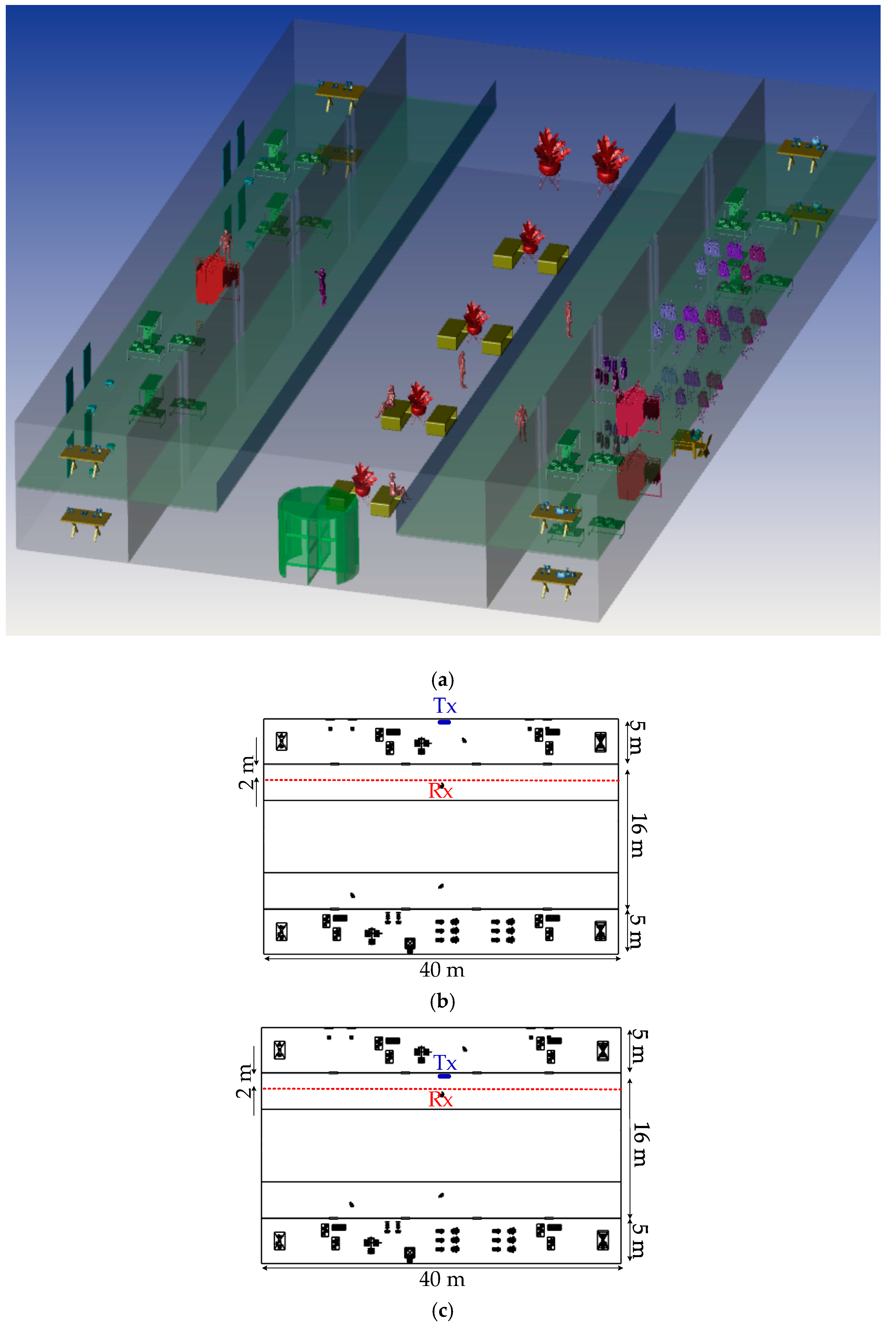
To determine the detected optical power and path lengths from the Tx to the Rx, non-sequential ray-tracing approach was used in the 3D environment. It evolves the specification and location of the Tx and the Rx, features of the CAD models of objects, wavelength-dependent reflectance of surfaces (wall, ceiling, floor, and objects), and transmission/reflection coefficient of glass windows. Next, the captured output data of the OpticStudio® is processed in MATLAB to obtain the CIR expressed as given by [27,32]:
h ( t ) = i = 1 N P i δ ( t τ i ) ,
where Pi and τ i are the power and the propagation time of the ith ray, respectively. δ is Dirac delta function and N is the number of rays received at the Rx. Note, a number of reflections from the floor, ceiling, walls, and other objects are considered until the normalized intensity of rays after intercepting an object drops to 10−3.
The spatial intensity distribution of light emitted from the light source is determined by the optical radiation pattern profile. The luminous intensity defined in terms of the angle of irradiance ϕ is given as [1]:
I ( ϕ ) = m L + 1 2 π I ( 0 ) cos m L ( ϕ ) , ϕ = [ π 2 , π 2 ]
where I(0) is the center luminous intensity of the OLED and mL is Lambertian order, which is defined in terms of the Tx semi-angle ϕ 1/2 as [1]:
m L = ln ( 2 ) ln [ cos ( ϕ 1 / 2 ) ] .
As inputs of the simulator, the measured characteristics of a flexible OLED from UNISAGA with a size of 200 × 50 mm2, see Figure 1a, were used. The measured beam pattern of the flexible OLED for flat and a half-circular configuration is depicted in Figure 1b, showing symmetry but not fitting with Lambertian radiation pattern (the solid line for mL = 1). A close match between the simulated and the measured beam patterns can be seen in Figure 1b. The measured spectrum profile of the flexible OLED is presented in Figure 1c, showing the red, green, and two blue components at 620, 553 and 454 and 480 nm, respectively.

2.2. Scenarios

Figure 2 shows the analyzed example of an office environment designed with the size of 10 × 10 × 3 m3 and a number of objects within. Here, a curved OLED with the size 1 × 0.5 m2 is mounted on the wall with a curvature radius of 32 cm. In the office environment, the scenario is to move the Rx over a semi-circular path, where the radius d is 2 m. An angle of radiation θ with respect to the normal from the center point of OLED (i.e., −90° < θ < 90°) is given, see Figure 3. The Rx height is assumed to be 1 m above the floor to represent people holding mobile phones while sitting at their desks. In simulation, we have not considered the synchronization. However, in real time systems synchronization protocols defined by the standards will be adopted, which does not affect the transmission characteristics of the proposed system.
Figure 4a and Figure 5a then show the 3D corridor and semi-open corridor environments inside a shopping mall, respectively, in which OLED acts as a light source. The semi-open corridor is typical especially for upper floors of the shopping mall, so we have chosen an example when the user walks on the first floor, having shop windows on one side and an open space on the other side. The user is moving on the straight path along the corridor (show by the red dashed-lines in Figure 4b,c and Figure 5b,c). The Rx is positioned at the height of 1.3 m above the floor level (i.e., the holding position of mobile by people). The user is moving along the shop windows at a distance of 2 m on the path donated as dy from −20 to 20 m, where Tx is placed at 0 m position. For both empty and furnished corridor and semi-open environments, we have considered two scenarios of (case1), where the OLED panel is located on the inner shop wall behind the glass window and (case2) on the wall or shop window inside the corridor, see Figure 4b,c and Figure 5b,c. All the key system parameters adopted in this work, including the reflectance values of surfaces and the transmission coefficient of the glass windows, are given in Table 1.

3. Results

3.1. Comparison of Flat and Curved OLED Based System Performance

For intensity modulation/direct detection (IM/DD) optical transmission systems, the electrical SNR is defined as
SNR = ( γ P R ) 2 R b N o = ( γ H ( 0 ) P E ) 2 R b N o ,
where γ is the photodetector’s responsivity in (A/W), PE and PR are the emitted and received optical power, respectively, and N0/2 is double-sided power spectral density. Considering a link with non-return-to-zero (NRZ) on-off keying (OOK), the BER is given as [33]:
BER = 1 2 erfc ( SNR 2 ) .
Figure 6 shows the plots of the BER for flat and curved OLEDs at Rb of 4 and 6 Mb/s along with the 7% forward error correction (FEC) BER limit of 3.8 × 10⁻³ [1] for an office. Note, for 4 Mb/s the BER is below the FEC limit for curved OLED. As illustrated, the BER plot displays a symmetry about the origin (i.e., at θ of 0°) because of the same achievable SNR that is maintained across the entire face of OLED. It is obvious that, for the curved OLED the BER is improved over a wider θ compared with the flat OLED. Note, for the flat OLED with −30° < θ < 30° the BER values are <10−6. At Rb of 4 Mb/s, the BER remains below the FEC limit for θ within the range of ± 90° and ± 53° for the curved and flat OLEDs, respectively. However, for Rb of 6 Mb/s, θ drops by 15° and 4° for the curved and flat OLEDs, respectively.

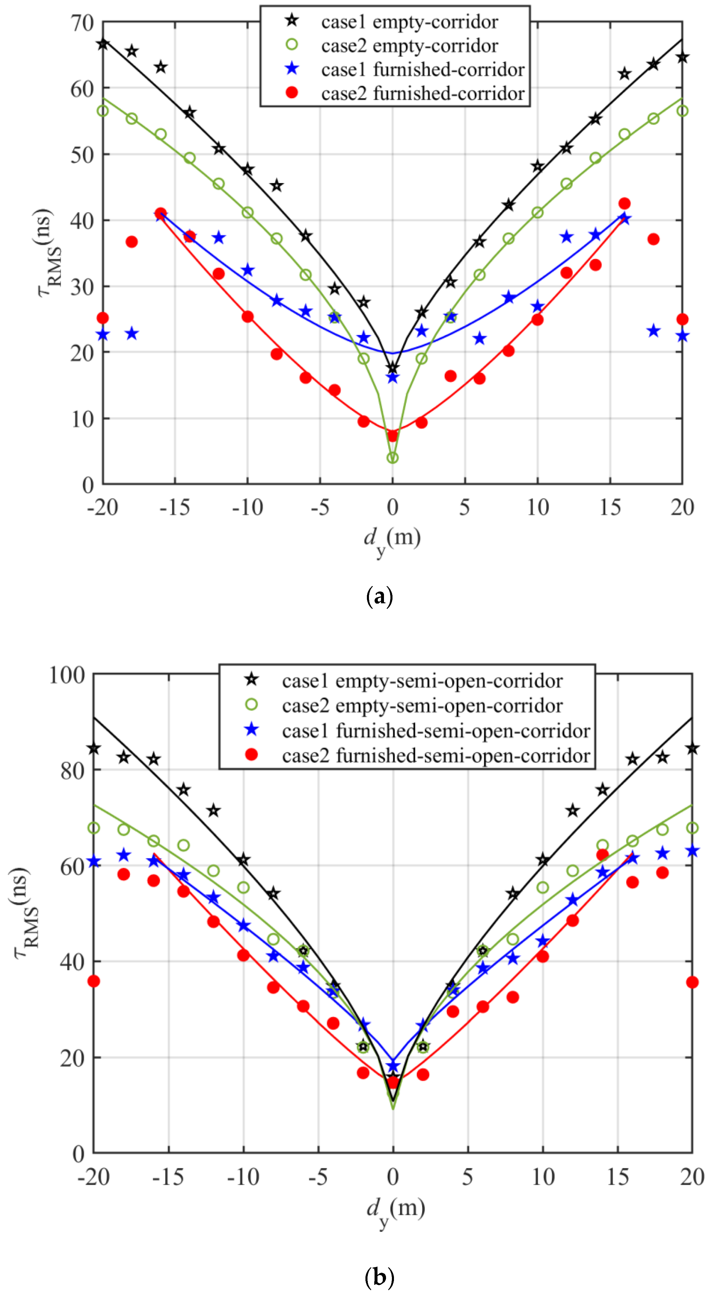
3.2. Channel Charactristics

The channel gain H(0) defines the achievable SNR for a given incident power. To quantify the data rate, H(0) and the optical signal attenuation OPL = −10log10(H(0)) caused by reflections and transmission in the free space are obtained [21,34]. The RMS delay spread is commonly used to define the time dispersion along the propagation path. The channel mean excess delay τ and the RMS delay spread τRMS are given as [27,31].
τ = 0 t × h ( t ) d t 0 h ( t ) d t ,
τ R M S = 0 ( t τ ) 2 × h ( t ) d t 0 h ( t ) d t .
Figure 7 depicts the τRMS plot for the flat and curved OLEDs in an office. The angle θ is shown in Figure 7 to identify the Rx’s location on the semi-circular path with the radius d. τRMS increases with θ reaching the maximum value of 5 and 10.7 ns at θ of 90° for the curved and flat OLEDs, respectively. It is obvious that, for the curved OLED, there is a slight change in τRMS by about 0.8 ns with respect to θ. However, τRMS has changed about 7.3 ns for the flat OLED. Note, there is a significant increase in τRMS for θ > 40° for the flat OLED.
Using a non-linear approximation algorithm for both cases, a two-term power series model can be derived from simulations for τ   RMS as a function of θ given by
τ RMS = p 1 θ p 2 + p 3 ,
where p1, p2 and p3 are summarized in Table 2. Note, the empirical parameters can vary based on the number of objects in the room and the size of the specified confined space.
Figure 8 shows the azimuthal dependence of the OPL distributions for flat and curved OLEDs for the proposed scenario in an office. OPL increases with θ reaching a maximum of 60.4 and 70.2 dB at θ of 90° for curved and flat OLEDs, respectively. Note, up to ~14 dB drop in the channel gain can be seen for the flat OLED when θ changes from 0° to 90°, which is considerably higher compared with the reduced ~2 dB channel gain for curved OLED. It can be seen that, for the flat OLED and θ < 30° there is an improvement in OPL by ~1.8 dB compared with the curved OLED. However, for θ > 45°, there is high received power enhancement for the curved OLED compared with the flat OLED, e.g., OPL penalties for flat OLED are 5 and 10 dB for θ of 75° and 90°, respectively. In addition, for both cases OPLs can be determined as the 2-term power series models as
OPL = a 1 θ a 2 + a 3 ,
where the derived parameters a1, a2 and a3 are shown in Table 3.
Figure 9 and Figure 10 illustrate the channel characteristics for both open and semi-open corridor when OLED are mounted on the inner shop wall behind the glass window and on the wall or shop window inside the corridor while the user is moving along the corridor in terms of OPL and τRMS. As can be seen, both OPL and τRMS plots show symmetry about the center of the indoor environment with minimum values at the center. Note, τRMS for furnished rooms is lower than the empty room for both corridor and semi open-corridor; e.g., in a semi-open corridor and case1, the τRMS values are 42.5 and 52.7 ns at 8 m and 52.2, 66.6 ns at 12 m for furnished and empty, respectively.
In furnished environments, τRMS increases with the distance reaching the maximum value of 40 and 60 ns at a distance of 16 m for the corridor and semi-open corridor, respectively. In all environments, τRMS drop significantly for case2 compared with case1. Note, in both furnished environments, there is a huge drop in τRMS for case2 compared with case1 for dy up to 10 m; however, for dy > 10 m τRMS for case2 reaches the corresponding value of case1. E.g., in a furnished corridor, for case2, τRMS values are lower than case1 by 13, 6 and 2 ns at dy = 0, 8 and 14 m, respectively. However, in an empty corridor τRMS for case2 drop by 11, 5 and 5 ns at dy = 0, 8 and 14 m, respectively.
Note, positioning OLEDs behind the window will result in decreased received optical power compare with when located on the outer-wall of shops inside the corridor; i.e., OPL for case2 is lower than case1 in all empty and furnished indoor environments. For instance, in a furnished semi-open corridor for case1, OPL penalties of 6.5, 4.8, 3.4, and 1.6 dB at 5, 10, 15, and 20 m, respectively, can be seen in comparison to case2. Additionally, for both cases, OPL in the corridor is lower compared with the semi-open corridor. e.g., in furnished environments and case2, OPL in the corridor reaches the maximum of 87.6 dB, which is lower than the value corresponding to the semi-open corridor (i.e., 90.7 dB). Note, the channel gain for both cases in furnished environments for dy < 4 m remains the same; however, for case1 and dy > 4 m, the OPL penalty of the furnished semi-open corridor is ~1 dB in contrary with the furnished corridor. For case2, there is a drop in OPL for the furnished corridor by 1.7 and 2.4 dB at dy of longer distances of 10 and 15 m in comparison with the furnished semi-open corridor.
In addition, the channel gain enhancement in an empty corridor in contrary with furnished one is 5 dB at 5 m reaching 7 dB at 15 m for case1. However, for case2 it remains around 4 dB for dy > 4 m. In addition, the channel gain enhancement in an empty semi-open corridor in contrary with furnished one are 7.2 and 5 dB at 5 m increasing to 9.1 and 7 dB at 15 m for case1 and case2, respectively.
Using a non-linear approximation algorithm for both cases in all environment, a two-term power series model have been derived from simulations for τ RMS and OPL as a function of dy given by
τ RMS = r 1 d y r 2 + r 3 ,
OPL = l 1 d y l 2 + l 3 ,
where the derived values of r1, r2, r3, l1, l2, and l3 are summarized in Table 4 and Table 5.

4. Conclusions

In this paper, we investigated the performance of OLED-based VLC system and the channel characteristics in office, corridor, and semi-open environments. The measured beam pattern profile of the curved OLED was closely matched with the simulation result. We showed that, when a flat OLED was used in an office, τRMS increased significantly by 7.3 ns compared with 1 ns for the curved OLED. In the office, contrary to the flat OLED, the curved OLED showed improved BER performance over a wider range of θ. A data rate of 4 Mb/s was achieved using both the curved and flat OLEDs for θ within the range of ±90° and ±53°, respectively. A two-term power series model was found to match τRMS and OPL as a function of θ and dy for the office and corridors, respectively and models’ parameters for all three environments with and without furniture were derived. We showed that, when OLED is positioned on the outer wall of shops inside the corridor, the channel gain enhanced in contrast to them being located on inner shop wall, e.g., the channel gain enhanced by 5.2 and 4.8 dB at 10 m for furnished corridor and semi-open corridor, respectively. Moreover, the channel gain in the corridor was higher compared with the semi-open corridor. As a result, for case2, there was an enhancement in the channel gain for the furnished corridor by 1.7 and 2.4 dB at dy of 10 and 15 m in comparison with the furnished semi-open corridor.

Author Contributions

The contributions of the authors in this paper are the following: conceptualization: Z.N.C., and S.Z.; investigation: Z.N.C., S.Z. and H.B.E.; methodology: Z.N.C., and S.Z.; project administration: S.Z., Z.G.; software: Z.N.C., and H.B.E.; validation: S.Z., Z.G., and M.U. All authors have read and agreed to the published version of the manuscript.

Funding

This work was supported by the European Union’s Horizon 2020 Research and Innovation Programme, under the Marie Sklodowska-Curie grant agreement no 764461 (VisIoN).

Conflicts of Interest

The authors declare no conflict of interest. The funders had no role in the design of the study; in the collection, analyses, or interpretation of data; in the writing of the manuscript; or in the decision to publish the results.

References

  1. Ghassemlooy, Z.; Alves, L.N.; Zvanovec, S.; Khalighi, M.A. Visible Light Communications: Theory and Applications; CRC Press: Boca Raton, FL, USA, 2017. [Google Scholar]
  2. Karunatilaka, D.; Zafar, F.; Kalavally, V.; Parthiban, R. LED based indoor visible light communications: State of the art. IEEE Commun. Surv. Tutor. 2015, 17, 1649–1678. [Google Scholar] [CrossRef]
  3. Wu, S.; Wang, H.; Youn, C.H. Visible light communications for 5G wireless networking systems: From fixed to mobile communications. IEEE Netw. 2014, 28, 41–45. [Google Scholar] [CrossRef]
  4. Aguiar, L.; de Saa, P.; Guerra, V.; Perez-Jimenez, R. Survey of VLC and OCC Applications on Tourism Industry: Potentials & Challenges. In Proceedings of the 2020 South American Colloquium on Visible Light Communications (SACVC), Santiago, Chile, 1–6 June 2020. [Google Scholar]
  5. Ji, R.; Wang, S.; Liu, Q.; Lu, W. High-speed visible light communications: Enabling technologies and state of the art. Appl. Sci. 2018, 8, 589. [Google Scholar] [CrossRef] [Green Version]
  6. Pathak, P.H.; Feng, X.; Hu, P.; Mohapatra, P. Visible light communication, networking, and sensing: A survey, potential and challenges. IEEE Commun. Surv. Tutor. 2015, 17, 2047–2077. [Google Scholar] [CrossRef]
  7. Karbalayghareh, M.; Miramirkhani, F.; Eldeeb, H.B.; Kizilirmak, R.C.; Sait, S.M.; Uysal, M. Channel Modelling and Performance Limits of Vehicular Visible Light Communication Systems. IEEE Trans. Veh. Technol. 2020, 69, 6891–6901. [Google Scholar] [CrossRef]
  8. Cheong, Y.K.; Ng, X.W.; Chung, W.Y. Hazardless biomedical sensing data transmission using VLC. IEEE Sens. J. 2013, 13, 3347–3348. [Google Scholar] [CrossRef]
  9. Quintana, C.; Guerra, V.; Rufo, J.; Rabadan, J.; Perez-Jimenez, R. Reading lamp-based visible light communication system for in-flight entertainment. IEEE Trans. Consum. Electron. 2013, 59, 31–37. [Google Scholar] [CrossRef]
  10. Zhuang, Y.; Hua, L.; Qi, L.; Yang, J.; Cao, P.; Cao, Y.; Wu, Y.; Thompson, J.; Haas, H. A survey of positioning systems using visible LED lights. IEEE Commun. Surv. Tutor. 2018, 20, 1963–1988. [Google Scholar] [CrossRef] [Green Version]
  11. Nuwanpriya, A.; Ho, S.W.; Chen, C.S. Indoor MIMO visible light communications: Novel angle diversity receivers for mobile users. IEEE J. Sel. Areas Commun. 2015, 33, 1780–1792. [Google Scholar] [CrossRef]
  12. Eldeeb, H.B.; Selmy, H.A.; Elsayed, H.M.; Badr, R.I. Interference mitigation and capacity enhancement using constraint field of view ADR in downlink VLC channel. IET Commun. 2018, 12, 1968–1978. [Google Scholar] [CrossRef]
  13. Chen, C.; Zhong, W.D.; Yang, H.; Zhang, S.; Du, P. Reduction of SINR fluctuation in indoor multi-cell VLC systems using optimized angle diversity receiver. J. Lightw. Technol. 2018, 36, 3603–3610. [Google Scholar] [CrossRef]
  14. Hassan, N.B.; Ghassemlooy, Z.; Zvanovec, S.; Biagi, M.; Vegni, A.M.; Zhang, M.; Luo, P. Non-line-of-sight mimo space-time division multiplexing visible light optical camera communications. J. Lightw. Technol. 2019, 37, 2409–2417. [Google Scholar] [CrossRef]
  15. Teli, S.R.; Matus, V.; Zvanovec, S.; Perez-Jimenez, R.; Vitek, S.; Ghassemlooy, Z. Optical Camera Communications for IoT–Rolling-Shutter Based MIMO Scheme with Grouped LED Array Transmitter. Sensors 2020, 20, 3361. [Google Scholar]
  16. Strobel, N.; Droseros, N.; Köntges, W.; Seiberlich, M.; Pietsch, M.; Schlisske, S.; Lindheimer, F.; Schröder, R.R.; Lemmer, U.; Pfannmöller, M.; et al. Color-Selective Printed Organic Photodiodes for Filterless Multichannel Visible Light Communication. Adv. Mater. 2020, 32, 1908258. [Google Scholar] [CrossRef] [PubMed]
  17. Ghassemlooy, Z.; Arnon, S.; Uysal, M.; Xu, Z.; Cheng, J. Emerging optical wireless communications-advances and challenges. IEEE J. Sel. Areas Commun. 2015, 33, 1738–1749. [Google Scholar] [CrossRef]
  18. Ghassemlooy, Z.; Popoola, W.; Rajbhandari, S. Optical Wireless Communications: System and Channel Modelling with Matlab®; CRC Press: Boca Raton, FL, USA, 2019. [Google Scholar]
  19. Kalinowski, J. Organic Light-Emitting Diodes: Principles, Characteristics & Processes; CRC Press: Boca Raton, FL, USA, 2018. [Google Scholar]
  20. Kafafi, Z.H. Organic Electroluminescence; CRC Press: Boca Raton, FL, USA, 2018. [Google Scholar]
  21. Ghassemlooy, Z.; Khalighi, M.-A.; Dehao, W. Channel Modeling. In Visible Light Communications: Theory and Applications; CRC Press: Boca Raton, FL, USA, 2017; pp. 71–92. [Google Scholar]
  22. Chun, H.; Chiang, C.-J.; O’Brien, D.C. Visible light communication using OLEDs: Illumination and channel modeling. In Proceedings of the 2012 International Workshop on Optical Wireless Communications (IWOW), Pisa, Italy, 22 October 2012; pp. 1–3. [Google Scholar]
  23. Lee, K.; Park, H.; Barry, J.R. Indoor channel characteristics for visible light communications. IEEE Commun. Lett. 2011, 15, 217–219. [Google Scholar] [CrossRef]
  24. Ramirez-Aguilera, A.; Luna-Rivera, J.; Guerra, V.; Rabadán, J.; Perez-Jimenez, R.; Lopez-Hernandez, F.J. A generalized multi-wavelength propagation model for VLC indoor channels using Monte Carlo simulation. Trans. Emerg. Telecommun. Technol. 2019, 30, e3490. [Google Scholar] [CrossRef]
  25. Rodríguez, S.P.; Jiménez, R.P.; Mendoza, B.R.; Hernández, F.J.L.; Alfonso, A.J.A. Simulation of impulse response for indoor visible light communications using 3D CAD models. EURASIP J. Wirel. Commun. Netw. 2013, 2013, 7. [Google Scholar] [CrossRef] [Green Version]
  26. Zemax OpticStudio 18.9. Available online: http://www.zemax.com/products/opticstudio (accessed on 10 October 2020).
  27. Miramirkhani, F.; Uysal, M. Channel modeling and characterization for visible light communications. IEEE Photonics J. 2015, 7, 1–16. [Google Scholar] [CrossRef]
  28. Uysal, M.; Miramirkhani, F.; Narmanlioglu, O.; Baykas, T.; Panayirci, E. IEEE 802.15. 7r1 reference channel models for visible light communications. IEEE Commun. Mag. 2017, 55, 212–217. [Google Scholar] [CrossRef]
  29. Eldeeb, H.B.; Uysal, M.; Mana, S.M.; Hellwig, P.; Hilt, J.; Jungnickel, V. Channel modelling for light communications: Validation of ray tracing by measurements. In Proceedings of the 12th IEEE/IET International Symposium on Communication Systems, Networks and Digital Signal Processing (CSNDSP), Porto, Portugal, 20–22 July 2020. [Google Scholar]
  30. Chen, H.; Xu, Z. OLED panel radiation pattern and its impact on VLC channel characteristics. IEEE Photonics J. 2017, 10, 1–10. [Google Scholar] [CrossRef]
  31. Chaleshtori, Z.N.; Zvanovec, S.; Ghassemlooy, Z.; Eldeeb, H.B.; Uysal, M. A Flexible OLED VLC System for an Office Environment. In Proceedings of the 12th IEEE/IET International Symposium on Communication Systems, Networks and Digital Signal Processing (CSNDSP), Porto, Portugal, 20–22 July 2020. [Google Scholar]
  32. Chaleshtori, Z.N.; Zvanovec, S.; Ghassemlooy, Z.; Eldeeb, H.B.; Uysal, M. Coverage of a shopping mall with flexible OLED-based visible light communications. Opt. Express 2020, 28, 10015–10026. [Google Scholar] [CrossRef] [PubMed]
  33. Pinho, P. Optical Communication Technology; IntechOpen: London, UK, 2017. [Google Scholar]
  34. Proakis, J.G.; Salehi, M. Digital Communications; McGraw-Hill: New York, NY, USA, 2001. [Google Scholar]
Figure 1. The flexible organic light emitting diodes (OLED) panel and its characteristics adopted in the simulation: (a) photograph, (b) the emission pattern of light source modeled for a flat and curved OLED, which is closely matched with the measured data, and (c) the normalized optical spectrum where the peak wavelengths are marked.
Sensors 20 06869 g001
Figure 2. The three-dimensional office environment.
Sensors 20 06869 g002
Figure 3. The proposed scenario which shows the location of receiver (Rx) and transmitter (Tx) giving a half-circular lighting.
Sensors 20 06869 g003
Figure 4. (a) The three-dimensional corridor environment and proposed scenarios which show the location of Rx and Tx, (b) case1 where Tx is located on inner shop wall behind window, and (c) case2 on wall or shop window inside the corridor.
Sensors 20 06869 g004
Figure 5. (a) The three-dimensional semi-open corridor environment and proposed scenarios which show the location of Rx and Tx, (b) where Tx is located on inner shop wall behind window (case1), and (c) on wall or shop window inside the corridor (case2).
Sensors 20 06869 g005
Figure 6. The bit-error-rate (BER) for flat and curved OLEDs at Rb of: (a) 4 Mb/s, and (b) 6 Mb/s for an office.
Sensors 20 06869 g006
Figure 7. Comparison of a flat and curved OLEDs employed in the office in term of τ R M S .
Sensors 20 06869 g007
Figure 8. Comparison of a flat and curved OLEDs employed in the office in term of optical path loss (OPL).
Sensors 20 06869 g008
Figure 9. Channel characteristics in term of τ RMS for both: (a) corridor, and (b) semi-open corridor environment; when OLED are mounted on the inner shop wall behind the glass window (case1) and on the wall or shop window inside the corridor (case2) while the user is moving along the corridor.
Sensors 20 06869 g009
Figure 10. Channel characteristics in term of OPL for both: (a) corridor, and (b) semi-open corridor environment; when OLED are mounted on the inner shop wall behind the glass window (case1) and on the wall or shop window inside the corridor (case2) while the user is moving along the corridor.
Sensors 20 06869 g010
Table 1. The system parameters.
ItemParameterValue
Surface material
refractivity in % (RGB)
Chair, sofa (leather)2418.816.3
Coffee cup (ceramics)97.196.292.3
Human clothes (cotton)675845.6
Plant (leaf)145.98.2
Desk, book shelf, book (pine wood)705133.1
Laptop, PC, printer, and telephone (black gloss paint)3.43.23.2
Transmission coefficient in % (RGB)Glass windows889087
Room sizeOffice 10   ×   10   ×   3 m3
Corridor 18   ×   40   ×   3 m3
Semi-open corridor 26   ×   40   ×   3 m3
TxDimension1 × 0.5 m2
TypeFlexible
Bandwidth50 kHz
Power of lighting10 W
Number of OLED panels19
Number of chip/LED panel64
Power of each chip8.2 mW
Curvature radius32 cm
Location in office(4, 0.33, 1.5) m
Location in corridor and semi-open corridorcase1: (0.1, 20, 1.5) m
case2: (4.9, 20, 1.5) m
ChannelTime resolution0.2 ns
RxActive area of PD1 cm2
Responsivity0.4 A/W
FOV90°
Incident angle
One sided noise power spectral density No10−19 W/Hz
Table 2. Numerical modeling parameters for τ RMS in the case of using flat and curved OLEDs in office.
OLED Typep1p2p3
Curved 8.707 × 10−104.5894.172
Flat1.765 × 10−52.8753.312
Table 3. Numerical modeling parameters for OPL in the case of using flat and curved OLEDs in office.
OLED Typea1a2a3
Curved 0.2964 × 10−21.46558.26
Flat9.315 × 10−52.64656.42
Table 4. Numerical modeling parameters for τ RMS in both corridor and semi-open corridor.
Environmentr1r2r3
case1 empty-corridor5.320.751916.83
case2 empty-corridor11.260.53582.446
case1 furnished-corridor0.4091.42419.79
case2 furnished-corridor0.8901.2967.947
case1 empty-semi-open corridor9.7770.703510.5
case2 empty-semi-open corridor11.90.56378.267
case1 furnished-semi-open corridor3.8600.86419.214
case2 furnished-semi-open corridor2.0201.14314.513
Table 5. Numerical modeling parameters for OPL in both corridor and semi-open corridor.
Environmentl1l2l3
case1 empty-corridor1.1600.85269.95
case2 empty-corridor7.8930.44653.01
case1 furnished-corridor6.3790.46965.823
case2 furnished-corridor10.0100.40354.130
case1 empty-semi-open corridor1.2650.83868.190
case2 empty-semi-open corridor6.9460.48053.670
case1 furnished-semi-open corridor6.4530.47066.451
case2 furnished-semi-open corridor8.0390.48556.180
Publisher’s Note: MDPI stays neutral with regard to jurisdictional claims in published maps and institutional affiliations.

