A Broadband Differential-Fed Dual-Polarized Hollow Cylindrical Dielectric Resonator Antenna for 5G Communications


Abstract
1. Introduction
2. Theory
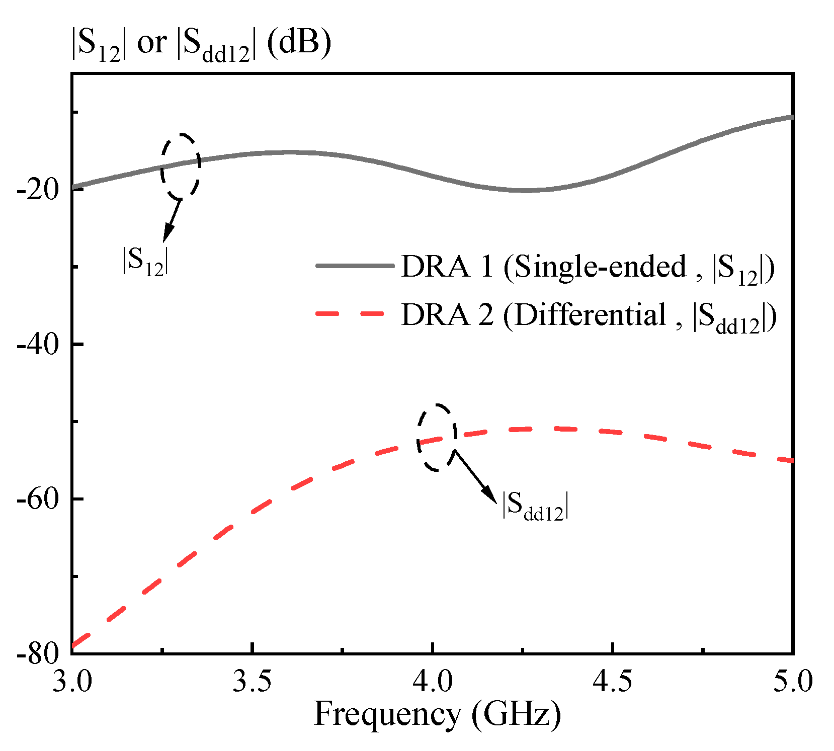
2.1. S Parameters of the Dual-Polarized Antennas Using the Single-Ended and Differential Ports
2.2. Strips-Fed Dual-Polarized Cylindrical DRA Using Single-Ended and Differential Ports
3. Antenna Configuration, Air Region Effect and Resonant Modes
3.1. Antenna Configuration
3.2. The Effect of the Air Region
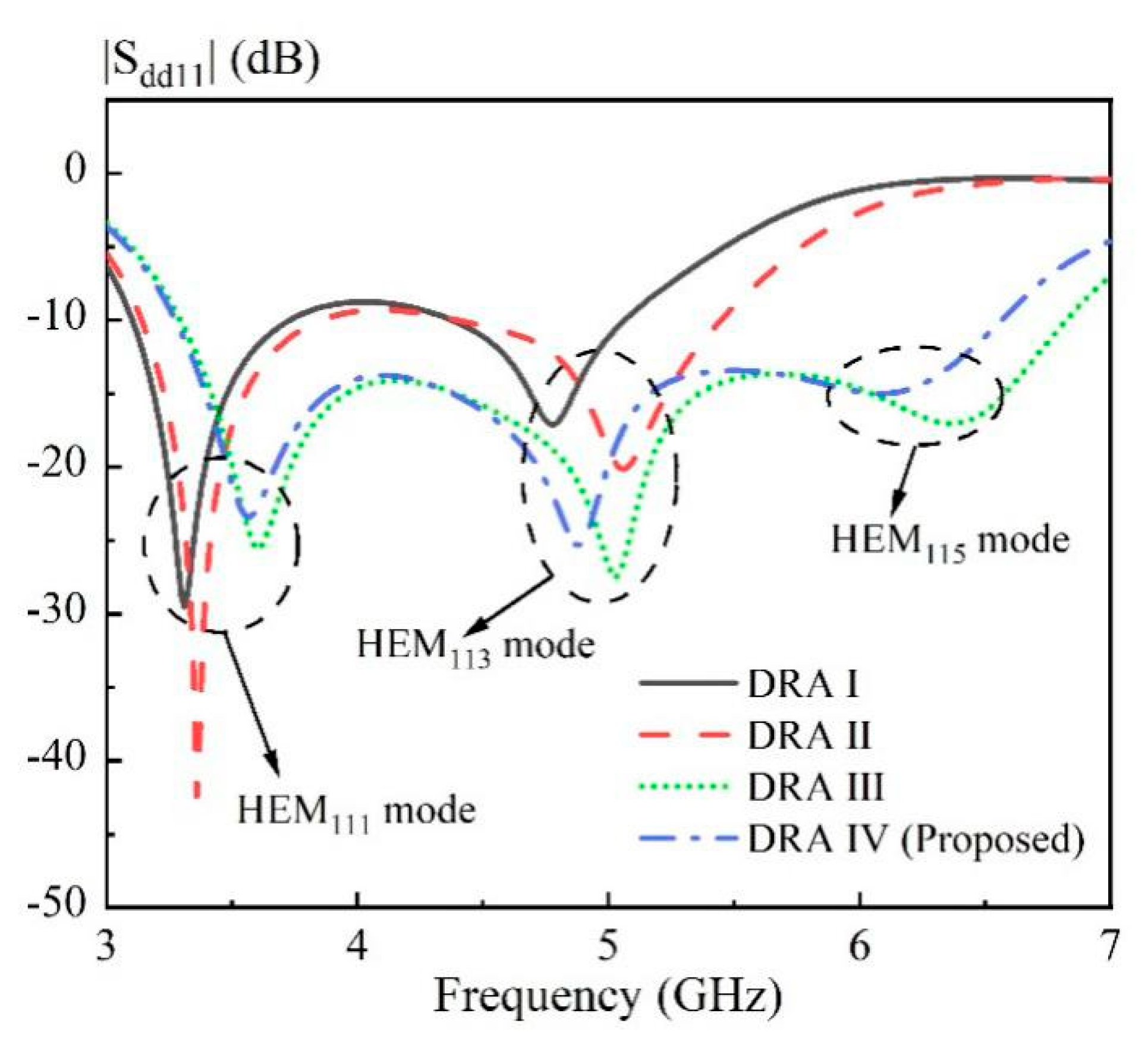
3.3. Resonant Modes
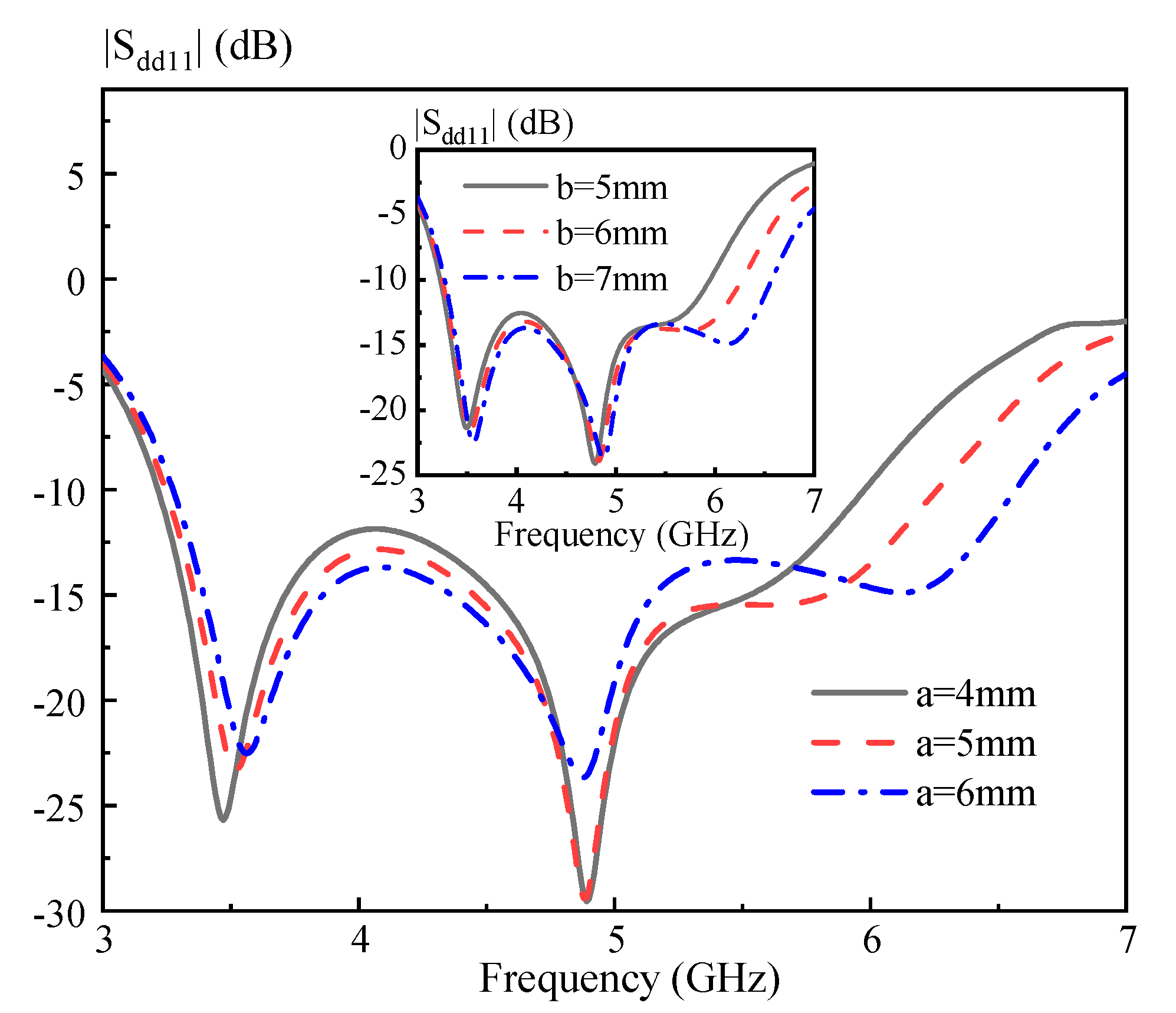
3.4. Parametric Study
- (1)
- Determining the dimension of the cylindrical DRA: R ~ 0.47 λd and H ~ 1.07 λd, in which λd is the wavelength in the dielectric corresponding to the center frequency;
- (2)
- Introducing four rectangular hollow regions (a ~ 0.26 λd, b ~ 0.3 λd and d ~ 0.39 λd) into the DRA, and then adjusting Ls to obtain a good matching;
- (3)
- Slightly adjusting a and b to obtain an optimal differential impedance bandwidth of the DRA;
- (4)
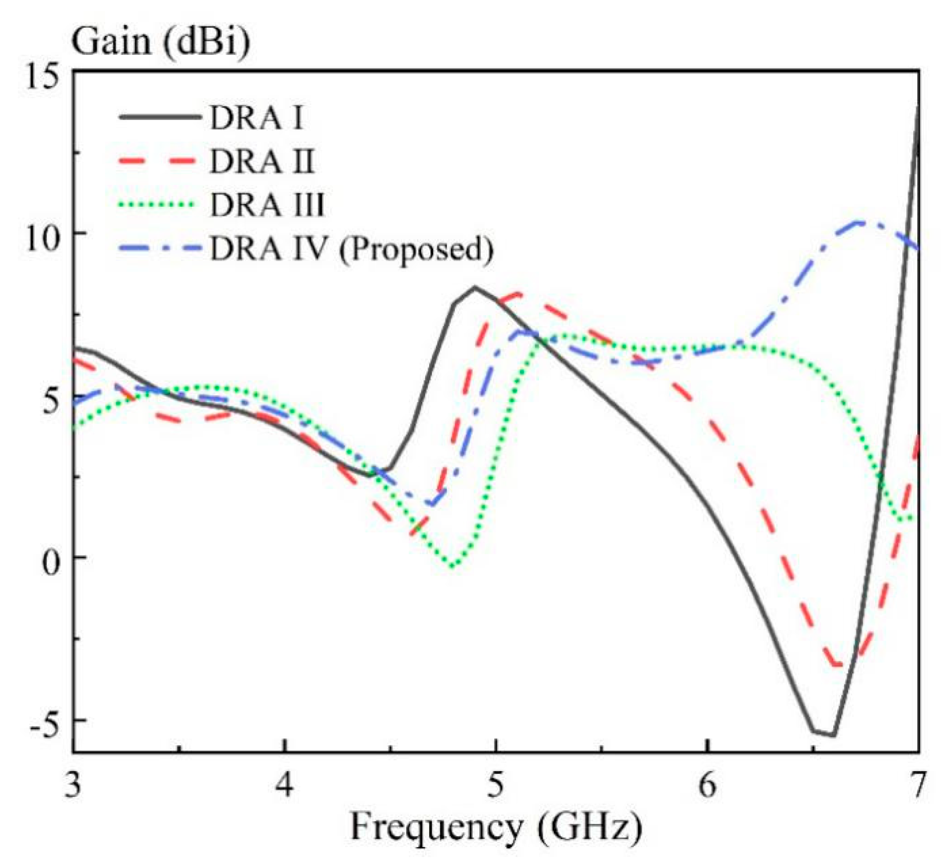
- Slightly adjusting d to optimize the antenna gain of the high frequency band.
4. Results
5. Conclusions
Author Contributions
Funding
Acknowledgments
Conflicts of Interest
References
- Long, S.A.; McAllister, M.W.; Shen, L.C. The resonant cylindrical dielectric cavity antenna. IEEE Trans. Antennas Propag. 1983, 31, 406–412. [Google Scholar] [CrossRef]
- Luk, K.M.; Leung, K.W. Dielectric Resonator Antennas; Research Studies Press: Hertfordshire, UK, 2003. [Google Scholar]
- Petosa, A. Dielectric Resonator Antenna Handbook; Artech House: Norwood, MA, USA, 2007. [Google Scholar]
- Gao, Y.; Feng, Z.H.; Zhang, L. Compact CPW-Fed dielectric resonator antenna with dual polarization. IEEE Antennas Wirel. Propag. Lett. 2011, 10, 544–547. [Google Scholar]
- Chair, R.; Kishk, A.A.; Lee, K.F. Hook- and 3-D J-shaped probe excited dielectric resonator antenna for dual polarization applications. IEEE Proc.-Microw. Antennas Propag. 2006, 153, 277–281. [Google Scholar] [CrossRef]
- Sun, Y.X.; Leung, K.W. Dual-Band and wideband dual-polarized cylindrical dielectric resonator antennas. IEEE Antennas Wirel. Propag. Lett. 2013, 12, 384–387. [Google Scholar] [CrossRef]
- Tang, X.R.; Zhong, S.S.; Kuang, L.B.; Sun, Z. Dual-polarized dielectric resonator antenna with high isolation and low cross-polarization. IET Electron. Lett. 2009, 45, 719–720. [Google Scholar] [CrossRef]
- Kowalewski, J.; Eisenbeis, J.; Jauch, A.; Mayer, J.; Kretschmann, M.; Zwick, T. A mmW broadband dual-polarized dielectric resonator antenna based on hybrid modes. IEEE Antennas Wirel. Propag. Lett. 2020, 19, 1068–1072. [Google Scholar] [CrossRef]
- Zou, L.F.; Abbott, D.; Fumeaux, C. Omnidirectional cylindrical dielectric resonator antenna with dual polarization. IEEE Antennas Wirel. Propag. Lett. 2012, 11, 515–518. [Google Scholar] [CrossRef]
- Zou, L.F.; Fumeaux, C. A cross-shaped dielectric resonator antenna for multifunction and polarization diversity applications. IEEE Antennas Wirel. Propag. Lett. 2011, 10, 742–745. [Google Scholar] [CrossRef]
- Lin, T.; Chiu, T.; Chang, Y.; Hsieh, C.; Chang, D. Design of 60-GHz dual-polarization dielectric resonator antenna. In Proceedings of the 2016 46th European Microwave Conference (EuMC), London, UK, 4–6 October 2016; pp. 1267–1277. [Google Scholar]
- Ali, A.; Yun, J.; Ng, H.J.; Kissinger, D.; Giannini, F.; Colantonio, P. Sub-THz on-chip dielectric resonator antenna with wideband performance. In Proceedings of the 2019 14th European Microwave Integrated Circuits Conference (EuMIC), Paris, France, 1–3 October 2019; pp. 358–361. [Google Scholar]
- Deng, X.; Li, Y.; Liu, C.; Wu, W.; Xiong, Y. 340 GHz on-chip 3-D Antenna with 10 dBi gain and 80% Radiation Efficiency. IEEE Trans. Terahertz Sci. Technol. 2015, 5, 619–627. [Google Scholar] [CrossRef]
- Wang, L.; Sun, W.Z. A 60-GHZ differential-fed circularly polarized on-chip antenna based on 0.18-μm COMS technology with AMC structure. In Proceedings of the IET International Radar Conference 2015, Hangzhou, China, 14–16 October 2015; pp. 1–4. [Google Scholar]
- Sun, M.; Zhang, Y.P.; Chua, K.M.; Wai, L.L.; Liu, D.; Gaucher, B.P. Integration of Yagi antenna in LTCC package for differential 60-GHz radio. IEEE Trans. Antennas Propag. 2008, 56, 2780–2783. [Google Scholar] [CrossRef]
- Li, B.; Leung, K.W. On the differentially fed rectangular dielectric resonator antenna. IEEE Trans. Antennas Propag. 2008, 56, 353–359. [Google Scholar] [CrossRef]
- Lee, E.; Ong, M.L.C. Aperture coupled differentially fed DRAs. In Proceedings of the Asia Pacific Microwave Conference, Singapore, 7–10 December 2009; pp. 2781–2784. [Google Scholar]
- Guo, S.J.; Wu, L.S.; Leung, K.W.; Mao, J.F. Microstrip-fed differential dielectric resonator antenna and array. IEEE Antennas Wirel. Propag. Lett. 2018, 17, 1736–1739. [Google Scholar] [CrossRef]
- Fang, X.S.; Leung, K.W.; Lim, E.H.; Chen, R.S. Compact differential rectangular dielectric resonator antenna. IEEE Antennas Wirel. Propag. Lett. 2010, 9, 662–665. [Google Scholar] [CrossRef]
- Hao, C.X.; Li, B.; Leung, K.W.; Sheng, X.Q. Frequency-tunable differentially fed rectangular dielectric resonator antennas. IEEE Antennas Wirel. Propag. Lett. 2011, 10, 884–887. [Google Scholar] [CrossRef]
- Sun, Y.X.; Leung, K.W.; Mao, J.F. Dualfunction dielectric resonator as antenna and phase-delay-line load: Designs of compact circularly polarized/differential antennas. IEEE Trans. Antennas Propag. 2018, 66, 414–419. [Google Scholar] [CrossRef]
- Tong, C.W.; Tang, H.; Li, J.; Yang, W.W.; Chen, J.X. Differentially coplanar-fed filtering dielectric resonator antenna for millimeter-wave applications. IEEE Antennas Wirel. Propag. Lett. 2019, 18, 786–790. [Google Scholar] [CrossRef]
- Gupta, R.D.; Parihar, M.S. Differentially fed wideband rectangular DRA with high gain using short horn. IEEE Antennas Wirel. Propag. Lett. 2017, 16, 1804–1807. [Google Scholar] [CrossRef]
- Sun, S.J.; Jiao, Y.C.; Zhang, X.; Gao, Y. Design of a novel differential-fed wide-beam dielectric resonator antenna. In Proceedings of the 2019 International Conference on Microwave and Millimeter Wave Technology (ICMMT), Guangzhou, China, 19–22 May 2019; pp. 1–3. [Google Scholar]
- Tong, C.W.; Tang, H.; Qin, W.; Yang, W.W.; Zhang, X.F.; Chen, J.X. Differentially inserted-fed compact dual-band circularly polarized dielectric resonator antenna. IEEE Antennas Wirel. Propag. Lett. 2019, 18, 2498–2502. [Google Scholar] [CrossRef]
- Fang, X.S.; Shi, K.P.; Sun, Y.X. Design of the single-/dual-port wideband differential dielectric resonator antenna using higher-order mode. IEEE Antennas Wirel. Propag. Lett. 2020, 19, 1605–1609. [Google Scholar] [CrossRef]
- Tang, H.; Chen, J.X.; Yang, W.W.; Zhou, L.H.; Li, W.H. Differential dual-band dual-polarized dielectric resonator antenna. IEEE Trans. Antennas Propag. 2017, 65, 855–860. [Google Scholar] [CrossRef]
- Tang, H.; Tong, C.W.; Chen, J.X. Differential dual-polarized filtering dielectric resonator antenna. IEEE Trans. Antennas Propag. 2018, 66, 4298–4302. [Google Scholar] [CrossRef]
- Wang, X.Y.; Tang, S.C.; Yang, L.L.; Chen, J.X. Differential-fed dual-polarized dielectric patch antenna with gain enhancement based on higher order modes. IEEE Antennas Wirel. Propag. Lett. 2020, 19, 502–506. [Google Scholar] [CrossRef]
- Sun, R.Y.; Han, R.C. Design of dual-polarized differential feed dielectric resonator antenna. In Proceedings of the 2015 IEEE MTT-S International Microwave Workshop Series on Advanced Materials and Processes for RF and THz Applications (IMWS-AMP), Suzhou, China, 1–3 July 2015; pp. 1–3. [Google Scholar]
- Chen, J.X.; Tang, H.; Li, Y.L.; Qin, W. Differentially fed dielectric resonators. IEEE Microw. Mag. 2020, 20, 24–36. [Google Scholar] [CrossRef]
- Chu, L.C.Y.; Guha, D.; Antar, Y.M.M. Conformal strip-fed shaped cylindrical dielectric resonator: Improved design of a wideband wireless antenna. IEEE Antennas Wirel. Propag. Lett. 2009, 8, 482–485. [Google Scholar] [CrossRef]
- Denidni, T.A.; Rao, Q.J.; Sebak, A.R. Broadband L-shaped dielectric resonator antenna. IEEE Antennas Wirel. Propag. Lett. 2005, 4, 453–454. [Google Scholar] [CrossRef]
- Liang, X.L.; Denidni, T.A. H-shaped dielectric resonator antenna for wideband applications. IEEE Antennas Wirel. Propag. Lett. 2008, 7, 163–166. [Google Scholar]
- Liang, X.L.; Denidni, T.A.; Zhang, L.N. Wideband L-shaped dielectric resonator antenna with a conformal inverted-trapezoidal patch feed. IEEE Trans. Antennas Propag. 2009, 57, 271–274. [Google Scholar] [CrossRef]
- Chair, R.; Kishk, A.A.; Lee, K.F. Experimental investigation for wideband perforated dielectric resonator antenna. IET Electron. Lett. 2006, 42, 137–139. [Google Scholar] [CrossRef]
- Leung, K.W.; So, K.K. Theory and experiment of the wideband two-layer hemispherical dielectric resonator antenna. IEEE Trans. Antennas Propagat. 2009, 57, 1280–1284. [Google Scholar] [CrossRef]
- Tang, Z.Y.; Liu, J.H.; Cai, Y.M.; Wang, J.H.; Yin, Y.Z. A wideband differentially fed dual-polarized stacked patch antenna with tuned slot excitations. IEEE Trans. Antennas Propag. 2018, 66, 2055–2060. [Google Scholar] [CrossRef]
- Yang, X.J.; Ge, L.; Wang, J.P.; Sim, C.D. A differentially driven dual-polarized high-gain stacked patch antenna. IEEE Antennas Wirel. Propag. Lett. 2018, 17, 1181–1185. [Google Scholar] [CrossRef]
- Liu, N.W.; Zhu, L.; Zhang, X.; Choi, W.W. A wideband differential-fed dual-polarized microstrip antenna under radiation of dual improved odd-order resonant modes. IEEE Access 2017, 5, 23672–23680. [Google Scholar] [CrossRef]
- Fang, X.S.; Leung, K.W. Linear-/circular-polarization designs of dual-/wide-band cylindrical dielectric resonator antennas. IEEE Trans. Antennas Propag. 2012, 60, 2662–2671. [Google Scholar] [CrossRef]
- Fang, X.S.; Chen, S.M. Design of the wide dual-band rectangular souvenir dielectric resonator antenna. IEEE Access 2019, 7, 161621–161629. [Google Scholar] [CrossRef]
- Li, W.W.; Leung, K.W. Omnidirectional circularly polarized dielectric resonator antenna with top-loaded alford loop for pattern diversity design. IEEE Trans. Antennas Propag. 2013, 61, 4246–4256. [Google Scholar] [CrossRef]


 Simulation
  Measurement.
Simulation Measurement.
Measurement.
Simulation Measurement.


| Port Distribution | S Parameter | Diagrammatic Sketch |
|---|---|---|
| Two single-ended ports | Port matching: S11, S22 Port isolation: S21, S12 |  |
| Two differential ports | Port matching:
|  |
| Port isolation:
|
| Diff. Port (i) | Resonant Modes | Resonance Frequency | Mea. Diff. Impedance Bandwidth | ||
|---|---|---|---|---|---|
| Sim. (GHz) | Mea. (GHz) | Error (%) | |||
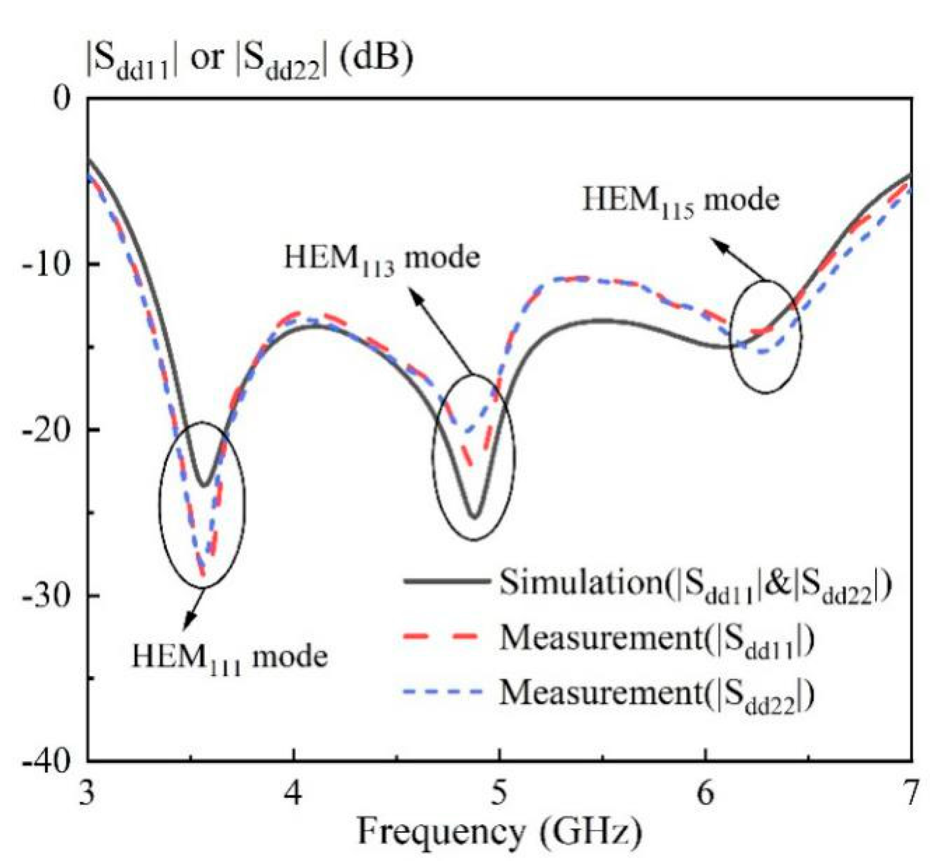
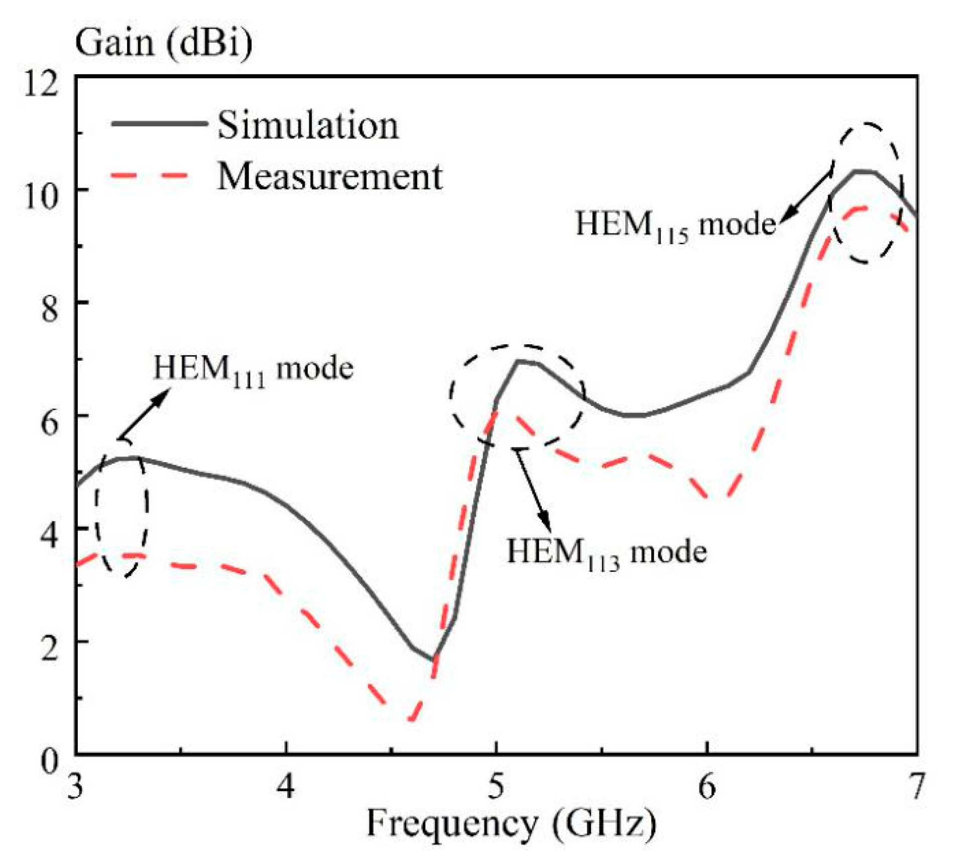
| 1 | HEM111y | 3.56 | 3.58 | 0.55 | 68.4% (3.23–6.59 GHz) |
| HEM113y | 4.88 | 4.88 | 0.00 | ||
| HEM115y | 6.08 | 6.26 | 2.87 | ||
| 2 | HEM111x | 3.56 | 3.56 | 0.00 | 69.4% (3.22–6.64 GHz) |
| HEM113x | 4.88 | 4.84 | 0.83 | ||
| HEM115x | 6.08 | 6.26 | 2.87 | ||
| Size (λd3) | Impedance Bandwidth (%) | Isolation (dB) (Worst within Band) | X-pol Level (dB) | Peak Gain (dBi) | Feeding Type | Consistence of the Radiation Patterns at Two Ports | |
|---|---|---|---|---|---|---|---|
| Ref. [4] | 0.219 | 7 | 25 | −20 | 6.45 | single-ended | Medium |
| Ref. [5] | 0.472 | 20 | 25 | −30 | NA. | single-ended | Good |
| Ref. [6] | 0.826 | 31.7 | 37 | −20 | 9.42 | single-ended | Medium |
| Ref. [7] | 0.294 | 7.9 | 36 | −34 | 6.8 | single-ended | Medium |
| Ref. [8] | 0.25 | 25 | 20 | −15 | 7.4 | single-ended | Good |
| Ref. [27] | 0.580 | 4.3 | 47 | −33 | 6.94 | Differential | Good |
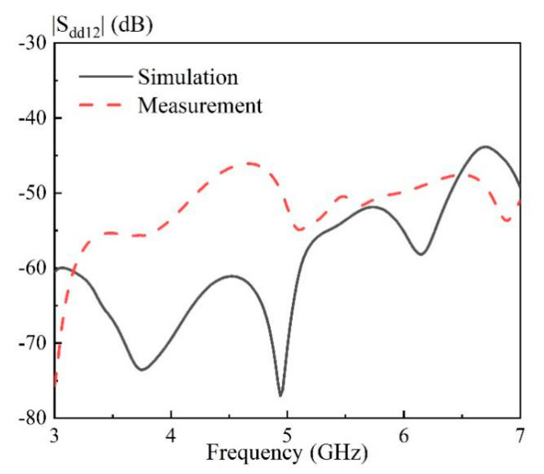
| Proposed | 0.747 | 68 | 46 | −22 | 9.67 | Differential | Good |
Publisher’s Note: MDPI stays neutral with regard to jurisdictional claims in published maps and institutional affiliations. |
© 2020 by the authors. Licensee MDPI, Basel, Switzerland. This article is an open access article distributed under the terms and conditions of the Creative Commons Attribution (CC BY) license (http://creativecommons.org/licenses/by/4.0/).
Share and Cite
Fang, X.; Shi, K.; Sun, Y. A Broadband Differential-Fed Dual-Polarized Hollow Cylindrical Dielectric Resonator Antenna for 5G Communications. Sensors 2020, 20, 6448. https://doi.org/10.3390/s20226448
Fang X, Shi K, Sun Y. A Broadband Differential-Fed Dual-Polarized Hollow Cylindrical Dielectric Resonator Antenna for 5G Communications. Sensors. 2020; 20(22):6448. https://doi.org/10.3390/s20226448
Chicago/Turabian StyleFang, Xiaosheng, Kangping Shi, and Yuxiang Sun. 2020. "A Broadband Differential-Fed Dual-Polarized Hollow Cylindrical Dielectric Resonator Antenna for 5G Communications" Sensors 20, no. 22: 6448. https://doi.org/10.3390/s20226448
APA StyleFang, X., Shi, K., & Sun, Y. (2020). A Broadband Differential-Fed Dual-Polarized Hollow Cylindrical Dielectric Resonator Antenna for 5G Communications. Sensors, 20(22), 6448. https://doi.org/10.3390/s20226448