1. Introduction
A coherent optical offset-quadrature amplitude modulation (OQAM)-based filter-bank multicarrier (CO-FBMC/OQAM) system has recently become a promising candidate for high-speed long-haul optical fiber transmission due to its higher spectral efficiency (SE) and its robustness to channel impairments [
1,
2,
3,
4,
5]. As a multicarrier modulation (MCM) technique, the FBMC is more robust against pulse dispersion and has less out-of-band leakage than orthogonal frequency division multiplexing (OFDM) [
6,
7,
8,
9,
10,
11,
12,
13,
14]. Meanwhile, the FBMC/OQAM scheme does not need cyclic prefix and, therefore, its SE can be increased remarkably [
15,
16].
The performance of optical fiber transmission system can be degraded severely by the phase noise (PN) [
17], and the MCM technique is especially vulnerable to PN like OFDM. In CO-FBMC/OQAM systems, the PN generally includes common phase error (CPE) and inter-carrier interference (ICI) [
18], similar to that in coherent optical OFDM (CO-OFDM) systems. Nevertheless, the original PN compensation (PNC) algorithms in CO-OFDM cannot be simply transplanted in CO-FBMC/OQAM systems. This is because the OQAM is employed between two immediate adjacent subcarriers, and the orthogonality between subchannels is ensured only in real plane. Due to the nonorthogonality in imaginary plane, the PNC and channel estimation techniques are severely restricted by the so-called intrinsic imaginary interference (IMI) in CO-FBMC/OQAM systems [
19,
20,
21,
22,
23,
24]. Consequently, many studies on the PNC method focus on the IMI cancellation [
25,
26,
27]. In [
26], a pilot-based PNC method is used to suppress the IMI at the expense of SE, where a pilot structure consists of several additional data symbols surrounding a pilot symbol. Another alternative approach is a coding scheme, and data symbols surrounding a pilot are deliberately coded to eliminate the IMI in that pilot [
26,
27]. Although the complexity of two mainly pilot-based PNC methods is moderate, their performance is limited by only CPE compensation.
At present, the PNC methods for CO-FBMC/OQAM systems can be classified into two categories: blind and pilot-aided PNC. As mentioned above, to cancel the IMI, the pilot-aided PNC methods have a low complexity and avoid the effect of cycle slips at the cost of the SE loss [
25,
26,
27]. Compared with the pilot-aided methods, the blind methods can achieve higher SE at the price of higher computational complexity (CC) [
28,
29,
30,
31,
32,
33,
34,
35,
36]. As a de-facto standard in coherent optical communication systems, the blind phase search (BPS) method can achieve a relatively good PNC effect and a high laser linewidth tolerance. Its main disadvantage is high CC resulting from a large number of test phases. The modified BPS (M-BPS) simplifies the distance calculation in the complex plane as the operations in the real plane [
28], and thereby reduces the number of multiplications significantly. However, both blind and pilot-aided methods mainly emphasize on the CPE compensation in frequency domain, and the ICI is not considered to be mitigated and is assumed to be additive noise in these studies. Because the MCM system with a large number of subcarriers can increase its fiber chromatic dispersion (CD) tolerance [
6], only CPE compensation is obviously not enough in this case due to serious negative impact of the ICI on the system performance [
25,
26,
27,
28].
Recently, time-domain ICI compensation has been proposed based on pilot symbols in either wireless or optical FBMC/OQAM systems [
18,
37]. An orthogonal-basis-expansion (OBE)-based PNC method has been proposed in a polarization-division-multiplexed CO-FBMC/OQAM system [
18]. With the aid of pilot symbols, the PN in time domain can be mitigated by estimating the corresponding coefficients of the OBE. In wireless FBMC/OQAM systems, by using the discrete cosine transform (DCT) method, the samples of the PN in time-domain can be described as sums of products of a group of DCT bases and their corresponding coefficients of the DCT [
37]. Using pilot symbols, the ICI effect can be tracked by calculating these coefficients of the DCT. It is obvious that the pilot overhead loss is very high for two time-domain pilot-based methods. Several blind ICI compensation schemes have been presented for CO-OFDM systems [
38,
39,
40], but they could not be used in CO-FBMC/OQAM systems.
In this paper, we propose a blind time-domain ICI compensation scheme for CO-FBMC/OQAM systems by combining the M-BPS method and DCT approximation of PN. The M-BPS method is used to obtain the pre-estimated values of the transmitted signals, with which the DCT coefficients can be obtained from the time-domain compensation model. To improve its performance and reduce its CC, the pre-decision error and the overlapped symbol structure are considered to develop the proposed algorithm. The proposed method is numerically validated in a 30 GBaud back to back (BTB) CO-FBMC/OQAM system. The numerical results show that the proposed algorithm achieves a significantly better performance compared to the M-BPS scheme while having a limited increase in CC.
The remainder of this paper is organized as follows. A theoretical model of CO-FBMC/OQAM system with laser phase noise is derived in
Section 2.
Section 3 introduces the principle of the proposed PNC method. In
Section 4, the overlapped symbol structure in the CO-FBMC/OQAM system is implemented to improve the effectiveness of the algorithm. We numerically investigate the performance of our method and propose the complexity analysis in
Section 5. Finally,
Section 6 summarizes the paper.
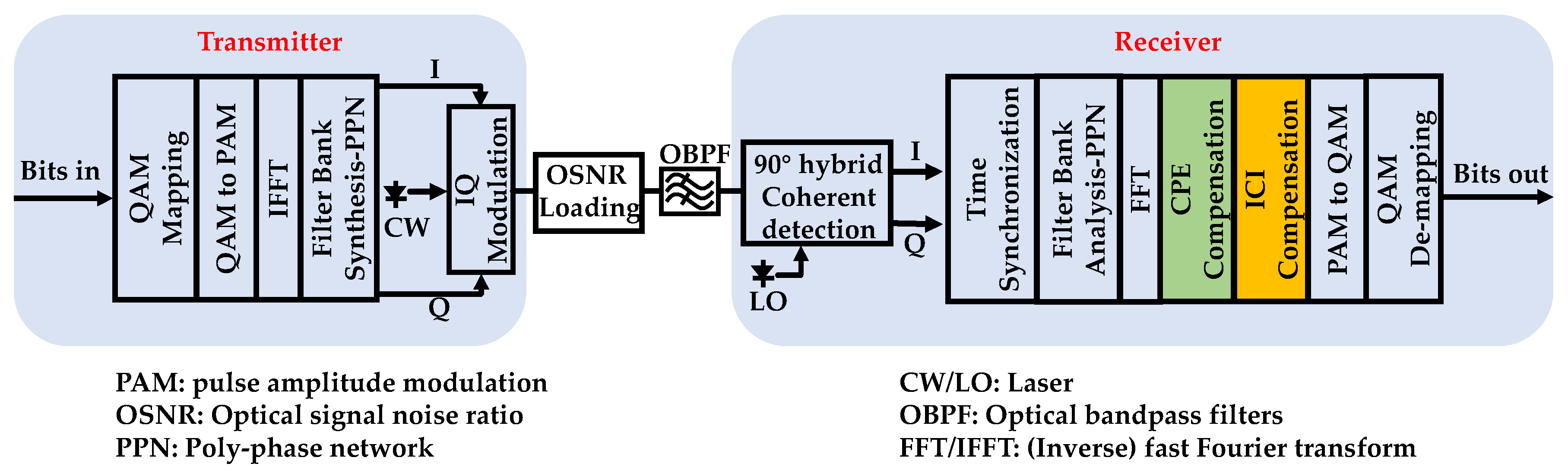
2. CO-FBMC/OQAM System with Laser Phase Noise
In this section, the influence of PN is studied in CO-FBMC/OQAM systems, and the analytical expressions of the PN induced interference are derived. As shown in
Figure 1, a single polarization CO-FBMC/OQAM BTB system is considered to investigate the PN induced interference and the performance of the proposed PNC algorithm. The single polarization BTB system is used to concentrate on the impact of laser PN in this paper.
At the transmitter, the process of OQAM pre-processing transforms the complex-valued QAM symbols into real-valued symbols, which means that the real-valued symbols are formed with the real and imaginary parts of QAM symbols destaggered by half a QAM symbol period. These real-valued symbols are modulated (i.e., pulse amplitude modulation (PAM)) in such a way that the FBMC system maintains the same data rate as the OFDM system without cyclic-prefix. Then, the PAM symbols are mapped onto a set of orthogonal subcarriers generated by an inverse fast Fourier transform (IFFT). The following operation is a cost-efficient poly-phase network (PPN) for filter bank synthesis implementation. With the digital signal processing (DSP) at the transmitter, its discrete time-domain transmitted signal,
s[
k], can be expressed as,
where
an,m and
gn,m[
k] are the PAM symbol and the synthesis filter at the (
n,
m)th time-frequency index, respectively;
NS is the total number of CO-FBMC/OQAM blocks; and
M is the total number of subcarriers in each CO-FBMC/OQAM block. The (
n,
m)th synthesis filter is described as,
where the square root raised cosine function
g[
k] is employed as the prototype filter with length
Lg [
41],
is phase modulation factor,
denotes the roll-off coefficient, and
represents the duration of the QAM complex symbols.
In the BTB CO-FBMC/OQAM system, under the impact of laser PN and additive Gaussian white noise (AWGN), the received signal
r[
k] can be written as,
Here, φ[k] denotes the PN in the time-domain, and the notation w[k] is the AWGN. The laser PN originates from either the external cavity laser at the transmitter or the local oscillator at the receiver. It is modeled as a random walk Wiener process, and the PN change follows a Gaussian distribution with zero mean and a specific variance , where is the combined laser linewidth, and TS is the normalized symbol period. Here, TS = (1/Br)/M, and Br is the baud rate of QAM symbols. The combined laser linewidth is defined as the sum of linewidths of the transmitter and receiver lasers. For the sake of simplicity, in the BTB system, the transmitter laser has the same linewidth as the received laser, and the combined laser linewidth is twice the linewidth of the single laser.
At the receiver side, the incoming optical wave signal is first coherently detected in a 90° optical hybrid. Subsequently, the obtained digital data are sent to the DSP modules to recover the original data. After a time synchronization is performed perfectly, a time-frequency translation can be completed by a hardware-efficient structure of PPN for filter bank analysis followed by a fast Fourier transform (FFT). Eventually, the complex-valued received demodulated signal at the (
n0,
m0)th time-frequency index can be written as,
here, the upper script “
” denotes conjugate operation. By substituting Equation (4) into Equation (5),
can be further expressed as [
18],
here,
denotes the filter processed additive noise, and
is defined as
at
is described by the following expression.
In Equation (6), is defined as the CPE for the information symbol , and it leads to phase rotation of the received constellation diagram. The second item of Equation (6) is defined as the ICI, which causes divergence of the received constellation diagram. The ICI in CO-FBMC/OQAM systems is a convolution between the coefficient and PAM symbols from different FBMC/OQAM blocks, while the ICI in CO-OFDM systems is a convolution between the ICI coefficients and different sub-carriers in one OFDM symbol. Hence, it is more difficult to compensate the ICI in CO-FBMC/OQAM systems.
In many previous studies, assuming that the PN time-domain samples are the same in one FBMC/OQAM symbol period, the complex-valued received signal
can be approximately rewritten as [
25,
26,
27,
28,
29],
where
is called the IMI in CO-FBMC/OQAM systems, and it is the interference term which results from neighboring PAM symbols on the interested (
n0,
m0)th position. Based on the approximation expression above, various studies have focused on the cancellation of the IMI by using pilot symbols [
25,
26,
27]. However, only CPE compensation effect can be improved through the complete removal of the IMI. Because the ICI effect is the convolution in frequency domain, it is useless to perform the ICI compensation by removing the IMI thoroughly. So in the rest of the paper, the blind ICI compensation is proposed for the CO-FBMC/OQAM systems.
3. Principle of the Phase Noise Compensation Method
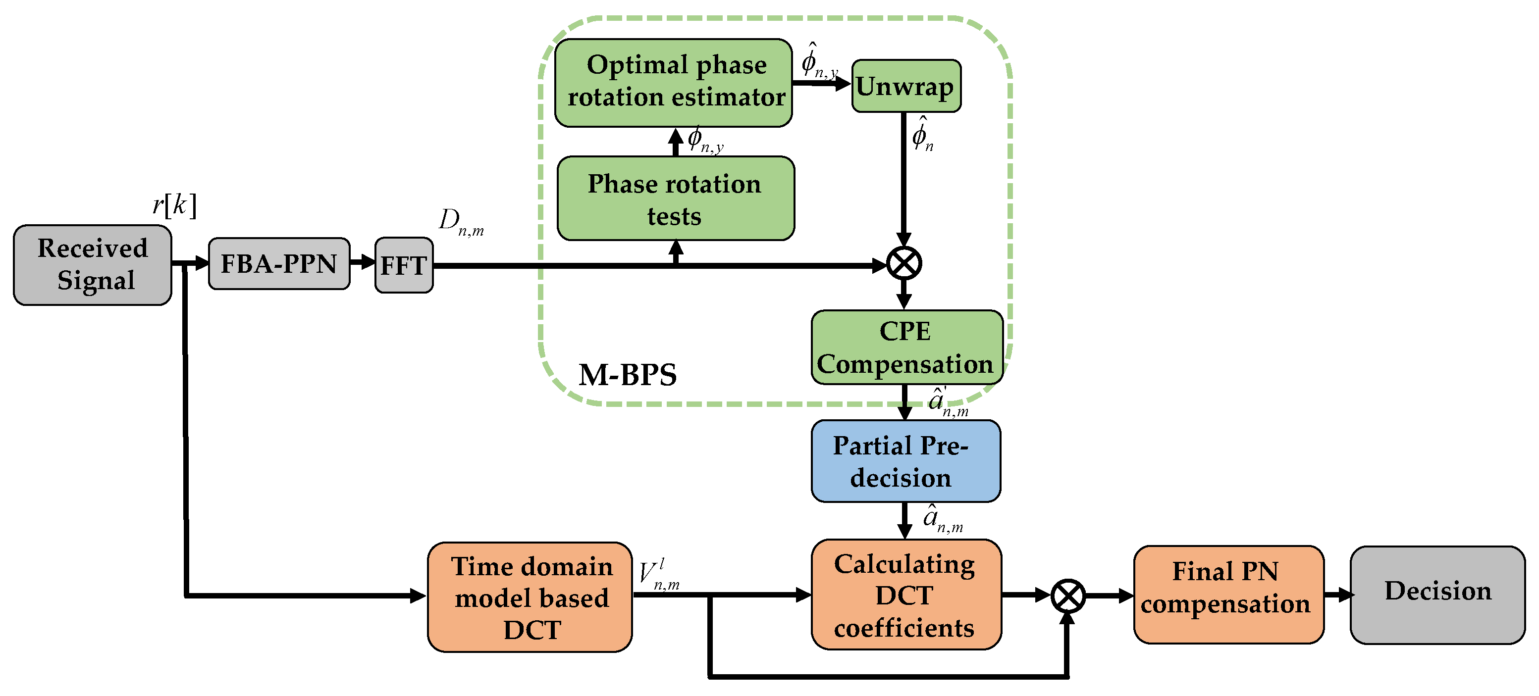
In this section, a blind PNC scheme is proposed to effectively compensate both CPE and ICI in CO-FBMC/OQAM systems.
Figure 2 shows a block diagram of the proposed blind PNC scheme. In this method, a time-domain PNC model is firstly built by using the DCT approximation method, where each PN sample can be expanded as a linear combination of DCT coefficients and a group of DCT bases. To calculate these DCT coefficients in the time-domain model, it is necessary to pre-estimate the transmitted frequency-domain signals. As a result, the CPE is firstly compensated by using the M-BPS algorithm [
28], and then the pre-decision process is performed on a part of the compensated signals to obtain the pre-estimated values of the transmitted signals.
After implementing PPN for filter bank analysis and FFT, the M-BPS method is firstly used to compensate the CPE. In the M-BPS method, the signal is firstly rotated by several test phases. The values of test phases are defined as
, where
y = 1, 2, …,
Y, and
Y is the total number of test phases. The rotated version of
can be given by
The estimated value of the CPE is obtained by minimizing the sum of distances between the hard decision of the received samples after test phase compensation and their projections on the real axis,
where
denotes the real projection operator, and
is the direct pre-decision operator. Subsequently, the conventional unwrap operation is performed to partly solve the problem of phase ambiguity [
42]. Then, the received PAM symbol is obtained as follows:
Next, the estimated values
of the transmitted signal are recovered via the pre-decisions upon the signal
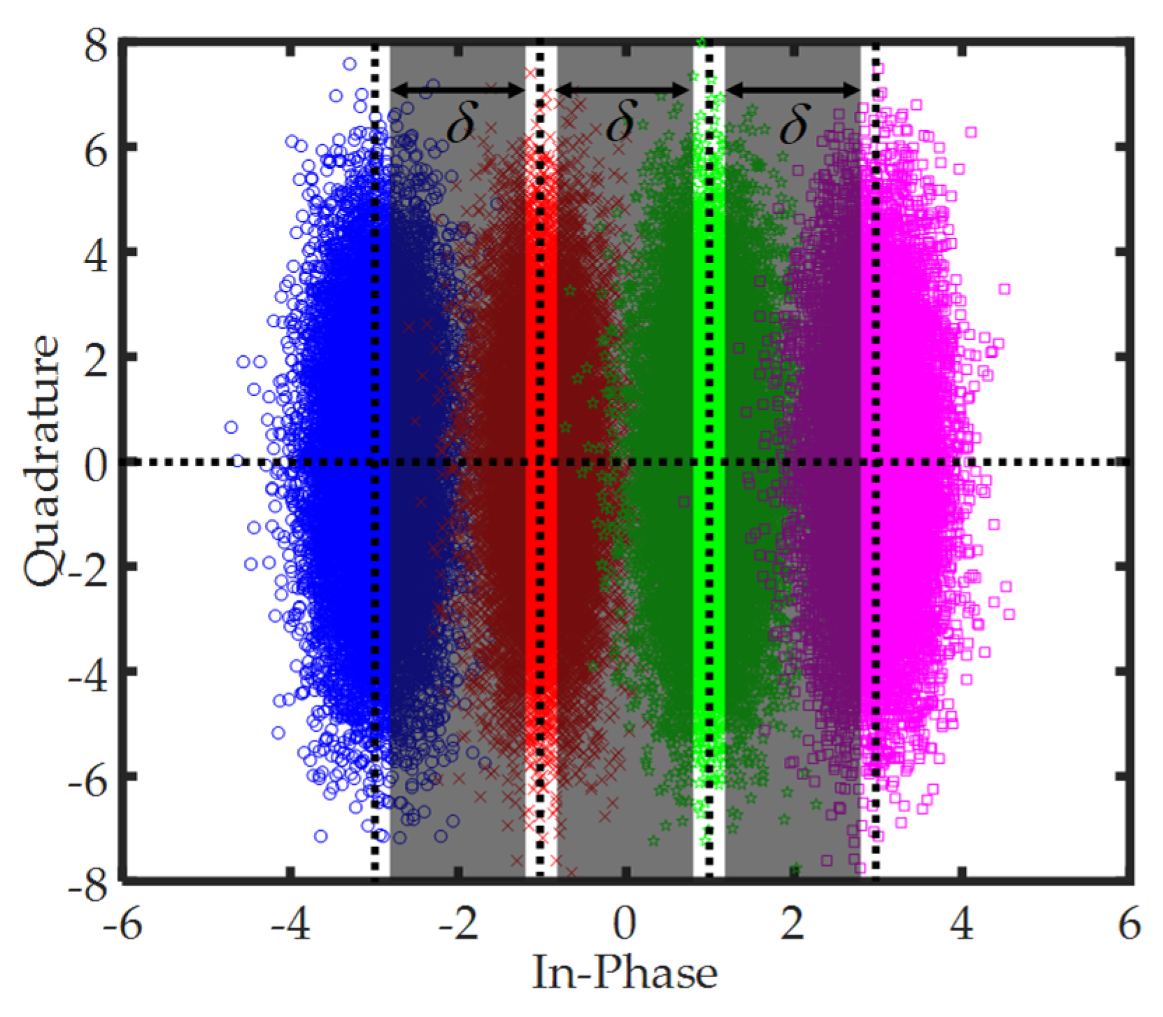
. Since the performance of the proposed method strongly depends on the pre-decisions, the negative influence of the decision errors should be considered. Here, an effective approach is taken to reduce the decision errors. As shown in
Figure 3, taking the 16-OQAM as an example, the constellation points are classified into 4 classes. When the constellation point
falls in the border regions between two neighbouring classes, the decision errors often occur. Then, three shadow border regions are regarded as the high decision error probability regions, where the parameter
is defined as is the width of a shadow rectangle, and it decides the selected range of the high decision error probability regions. Therefore, if
falls in these high decision error probability regions, these signals are thrown away and not used to perform pre-decisions; while
does not fall in the shadow regions, a hard pre-decision is made normally. However, if excessive signals are removed from the pre-decision process, this can lead to the performance degradation of the proposed method. Thus, the pre-decision parameter
needs to be optimized to achieve good performance.
Secondly, a time-domain PNC model is built to estimate the PN with the aid of DCT. The compensated signal
can be obtained by multiplying the received signal
rn[
i] by the complex conjugate of the estimate of PN,
where
φn[
i] denotes the
ith time-domain PN sample in the
nth CO-FBMC/OQAM block. The high frequency components in the PN can be neglected, and the complex conjugate of PN can be expressed as the linear combination of a group of DCT basis and DCT coefficients [
37],
where
and
are
L × 1 unknown DCT coefficient vector. Here,
is the transpose operator, and
L refers to the length of DCT coefficients. The
Lg ×
L matrix
τ of DCT basis is given by
substituting Equation (14) into Equation (13), the compensated temporal signal
can be rewritten as,
hence, the frequency domain compenstated symbol after analysis processing can be expressed as,
where
An,m is the received symbol when the PN is perfectly compensated — i.e., the transmitted PAM symbol
an,m can be recovered by taking real part of
An,m — and
is the noise term. By replacing
from Equation (16) into Equation (17), the symbol
is rewritten into
where the symbol
satisfies
By combining Equation (17) and Equation (18), the received symbol
An,m can be expressed as
While ignoring the noise term
, the corresponding estimated vector
can be approximated as,
where
and
(
).
is the estimated value of
An,m, and the
M × 1 vector
is a column of the matrix
.
Taking the real part of Equation (21) in the left and right sides, the equation is changed into
where
,
,
.
is the estimated value of the transmitted PAM symbol, and
denotes the imaginary projection operator. As above-mentioned, in order to reduce the decision errors, only partially estimated values of the transmitted signal can be obtained by making a pre-decision on the the constellation points in the low decision error probability regions. When the optimized parameter
is selected by balancing performance and complexity of the proposed algorithm, a
vector is picked out to perform the pre-decision, where
Zn is the total number of the pre-estimated transmitted signals in the
nth FBMC/OQAM block. The pre-estimated transmitted signal vector can be given by
, where the permutation matrix
is a
Zn ×
M matrix,
tz (
z = 1, 2, …,
Zn) represents the subcarrier index of
zth pre-estimated transmitted signal, and
is a
M × 1 vector
. Subsequently, Equation (22) can be rewritten as
Finally, the least square (LS) solution of the unknown DCT coefficient vector can be easily found as follows:
Once the DCT coefficient vector Qn is obtained, the PN, including the CPE and ICI, can be compensated via Equation (22).
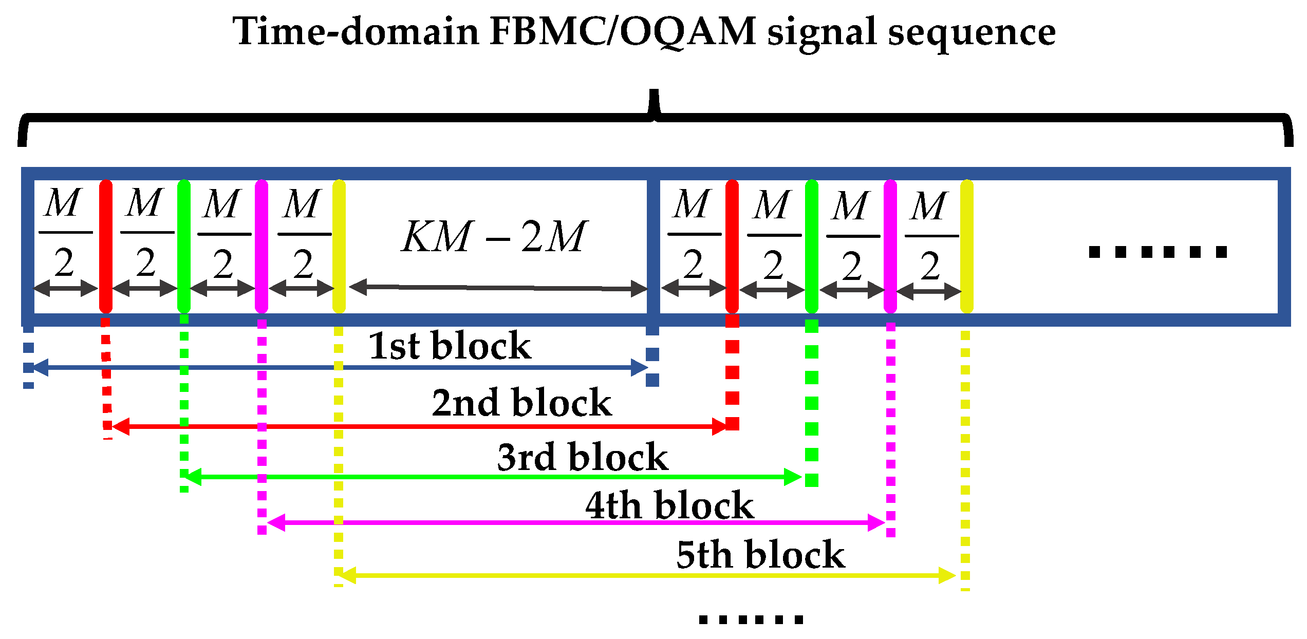
4. Modified Algorithm Based on Overlapped Symbol Structure
Different from OFDM symbols, neighboring temporal FBMC/OQAM blocks are overlapped with each other.
Figure 4 shows the time-domain FBMC/OQAM transmitted blocks with overlapped structure. The
ith sample of
nth received FBMC/OQAM block can be given by
Then, the last
KM-M/2 samples of
nth FBMC/OQAM block are the same as the first
KM-M/2 samples of (
n + 1)th FBMC/OQAM block—i.e.,
,
. As a consequence, the PN sample also satisfies that
, where
is the
jth sample of the (
n + 1)th PN vector
. Let
and
be the first and the last
KM-M/2 rows of DCT basis
, repectively, and we can obtain that
. Using LS estimation, the DCT coefficient vector
Cn for
nth CO-FBMC/OQAM block can be obtained as follows,
If the first DCT coefficient vector C1 is known, the other DCT coefficient vectors can be calculated according to the recursive expression in Equation (26). It is obviously unreasonable in such a way to calculate the other DCT coefficient vectors, because the updating between the PN vectors of and is not completely neglected. Moreover, two truncated matrices of and have very small singular values owing to the circularity of the DCT basis matrix . This leads to the significant degradation of the accuracy in the LS estimation. Therefore, an approximate expression between the DCT coefficient vectors of Cn and Cn+1 is derived to achieve high estimate accuracy.
Although the DCT basis matrix is not an orthogonal matrix in the proposed algorithm, the following condition is still satisfied:
where
b is a constant, and
I is a
L ×
L identity matrix. When the difference between the first and the last
M/2 samples of
and
are ignored,
can be approximated as the
M/2 circular shift of
. Hence, the terms satisfy that
where
and
are two
Lg ×
Lg circular shift matrices,
here,
0m × n denotes a
m ×
n zero matrix, and
In is a
n ×
n identity matrix. In combination with Equation (27), Equation (28) can be further expressed as
Assuming that three neighboring FBMC/OQAM blocks participate in the estimation process, Equation (21) can be expanded as
The matrices of
and
are separately defined as
and
Similar to Equations (22)–(24), the LS solution of the unknown DCT coefficient vector can be obtained from the following expression,
where
.
In the modified proposed algorithm, we throw away the first
M/2 samples of the (
n − 1)th PN vector
and the last
M/2 samples of the (
n + 1)th PN vector
; in spite of this, the relatively small power is on both ends of impulse response of the prototype filter so that the approximation affects rarely its performance, as the vector
Cn is obtained in such a way, and the vectors of
Cn − 1 and
Cn + 1 are easily calculated using the recurrence relations in Equations (30)–(31). Therefore, only one inverse operation in Equation (34) is required for every three neighboring FBMC/OQAM blocks, and the complexity can be decreased by the simplified operation. The detailed complexity analysis will be described in the next section. The acronyms used in this article are summarized in the following
Table 1.
5. Simulation Results and Discussion
A 30 GBaud BTB CO-FBMC/OQAM transmission system is simulated to evaluate the performance of the proposed blind PNC scheme, which is built by Optisystem 17.0 and MATLAB. Firstly, a pseudo-random bit sequence with a word length of 217 is mapped into m-QAM and the symbol rate is set to 30 GBaud/s. All the complex-valued QAM symbols are converted into the real-valued PAM symbols through QAM to PAM module. The base-band time-domain FBMC/OQAM symbols are generated after all PAM data sequences through IFFT and FBS-PPN. The pulse length of the square root raised cosine filter is chosen as Lg = 4M, and its roll-off coefficent .
Then, the base-band FBMC/OQAM signals are modulated onto an optical carrier at 1550 nm using a Mach–Zehnder modulator with a pair of independently controllable branches. At the receiver, the optical signal is coherently detected in a 90° optical hybrid, and the received analog signals are converted into digital signals by analog-to-digital converters with two samples per symbol. Subsequently, the obtained digital symbols are fed into the offline DSP module. With time synchronization being perfectly implemented, all the time-domain symbols are converted to the frequency domain by the PPN for filter bank analysis and FFT. In this paper, perfect channel equalization is considered, and specifically, we suppose that the channel response is flat and time-invariant on each carrier [
27]. Next, the blind discrete-cosine-transform-based phase noise compensation (BD-PNC) is implemented, including CPE and ICI compensation. In the related M-BPS algorithm, the total numbers of test phases for 4/16/64-QAM are chosen as 16/32/64, respectively [
28]. The original binary bits can be recovered after m-OQAM and m-QAM de-mapping, and the bit error rate (BER) is estimated by comparing them with the transmitted bits.
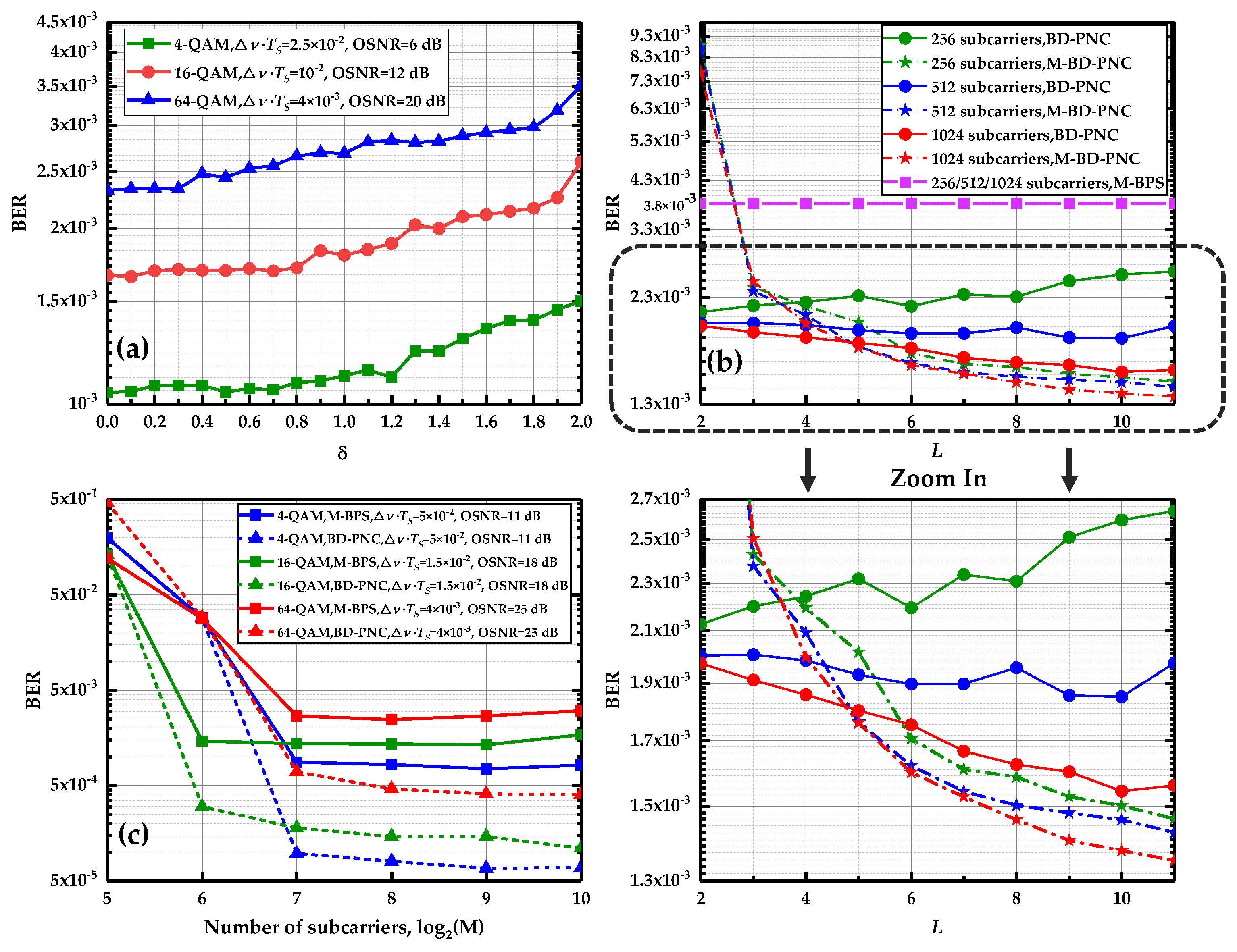
The effects of two parameters of
δ and
L on the performance of the algorithm are investigated in
Figure 5a,b.
δ is the width of shadow rectangle in a high decision error probability region, which determines how many signals after CPE compensation join the pre-decision process. As mentioned in
Section 3,
δ = 0 means that all the data are used to perform the pre-decision while
δ = 2 implies that only the leftmost and rightmost data in the I-Q plane participate in the process in
Figure 3. The decision error increases with the participation of more data after the CPE compensation. In
Figure 5a,
δ is optimized at the length of DCT basis
L = 2 for the CO-FBMC 4/16/64-QAM BTB system with 512 subcarriers. When the value of
δ is changed from 0 to 1.8, it can be seen that the BER performance does not degrade significantly due to the reduction in decision error probability. Moreover, with the increase in the value of
δ, the participation of a low number of data benefits greatly to complexity reduction in the proposed algorithm. Hence,
δ = 1.8 is adopted in the remainder of this paper.
L denotes the length of the DCT basis. Generally, under a large value of
L, we can obtain a more accurate approximation of the PN by the DCT in Equation (14).
Figure 5b displays the BER performance as a function of
L at the linewidth and symbol duration product
with 12 dB optical signal-to-noise ratio (OSNR) and 256/512/1024 subcarriers when using the proposed BD-PNC algorithm and its modified version. The modified algorithm is developed by considering the overlapped symbol structure, which is called the M-BD-PNC scheme. For the BD-PNC, with the increase in
L, the BER performance makes a small improvement, and is even deteriorated for the 256/512 subcarrier FBMC/OQAM systems. While using the M-BD-PNC method, there is a significant improvement for its BER performance as the value of
L is increased. The PN estimation precision depends on the accuracy of the DCT coefficients estimated by the LS method. In Equation (24) or Equation (34), if the matrix
or
does not meet the column full-rank condition, its LS solution could produce a large error. With the increase in the number of subcarriers, more rows in the matrix allow it to meet the column full-rank condition more easily. Hence, when
L is increased, the proposed BD-PNC algorithm achieves better performance under a large number of subcarriers; its performance becomes worse in the system with a low number of subcarriers, while in the M-BD-PNC method,
is the extended version of
so that it is easier for the matrix
to satisfy a column full-rank term. In this case, the PN estimation precision is almost not negatively influenced by the LS method, and a large value of
L contributes to the improvement of the PN estimation precision. Therefore, for the M-BD-PNC, the BER performance exhibits a better result at a large
L. The optimized values of
L in the BD-PNC and M-BD-PNC are selected as 2 and 10, respectively.
The CO-FBMC/OQAM system with a large number of subcarriers is robust against fiber CD [
12]. However, the PN becomes strong with the increase in the number of subcarriers. It is always a challenge for the existing PNC algorithm to achieve good performance under a large number of subcarriers [
18,
25,
26,
27,
28,
29]. So the performance of the proposed algorithm is evaluated in the BTB system with a large number of subcarriers. In
Figure 5c, the influence of the number of subcarriers on the performance of the method is investigated at
L = 2 and
δ = 1.8 using M-BPS and BD-PNC for the CO-FBMC 4/16/64 QAM systems with several different values of
and OSNR. When the number of subcarriers becomes larger, on one hand, the effect of AWGN is better averaged so that their performance is improved rapidly; on the other hand, the FBMC/OQAM symbol duration increases, and the PN has a larger variance and becomes stronger. As a result, it can be seen that the BER using M-BPS starts to deteriorate at
M = 1024. Note that the performance using BD-PNC remains almost unchanged when the number of subcarriers is increased from 128 to 1024 for 4/16/64-QAM modulation order. The simulation results prove that its performance is not sensitive to the number of subcarriers in the CO-FBMC/OQAM systems. Under the large number of subcarriers, the proposed algorithm is far superior to the M-BPS. For the 4-QAM modulation at
M = 1024 with
and 11 dB OSNR, the BER performance of BD-PNC is improved by more than one order of magnitude compared to the M-BPS.
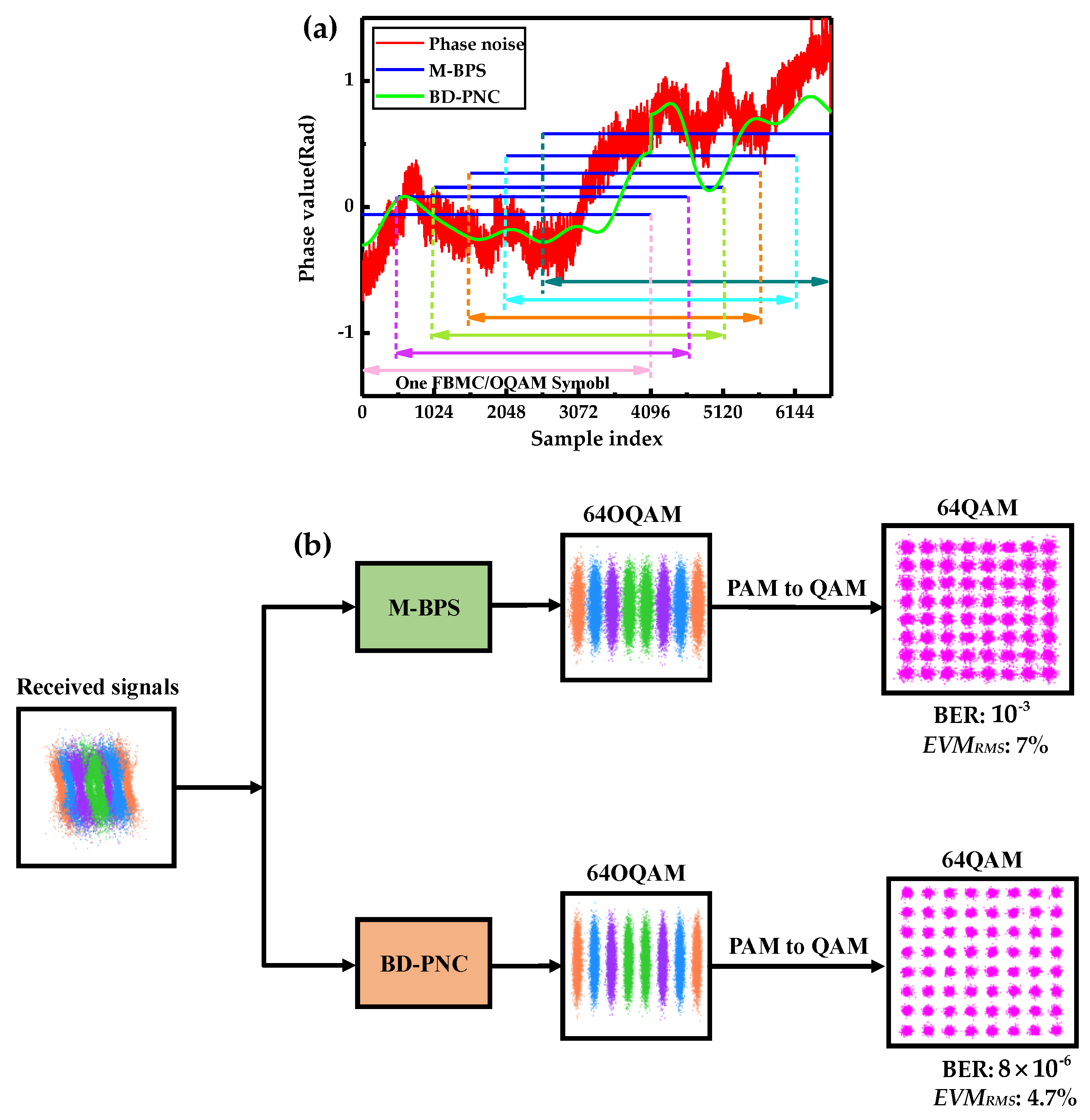
Figure 6a depicts one realization of the real PN and its estimation within six consecutive FBMC/OQAM blocks at the linewidth and symbol duration product
and an OSNR of 20 dB for 1024 sub-carrier 16-QAM CO-FBMC systems using the BD-PNC and M-BPS. For these time-domain overlapped symbols, the CPE estimated by the M-BPS is only a rough estimate of the PN, which is far from the real PN. The proposed method shows a better phase tracking capability due to the ICI compensation in time-domain.
Figure 6b shows the illustration of ICI influence and the necessity of PN estimation in time domain for CO-FBMC/OQAM systems. The constellation diagrams before and after PNC are separately displayed using M-BPS and BD-PNC with an OSNR of 27 dB and combined laser linewidth of 150 kHz. The PN in time domain, including CPE and ICI, is compensated by using BD-PNC, while only CPE is compensated by using M-BPS. It is clear that the PN in time domain is compensated by the proposed BD-PNC method resulting in an improvement of about 125 times in terms of BER over the M-BPS. Moreover, the BD-PNC achieves a root-mean-square error vector magnitude (
EVMRMS) of 4.7%, which is much lower than the
EVMRMS of 7% by the M-BPS.
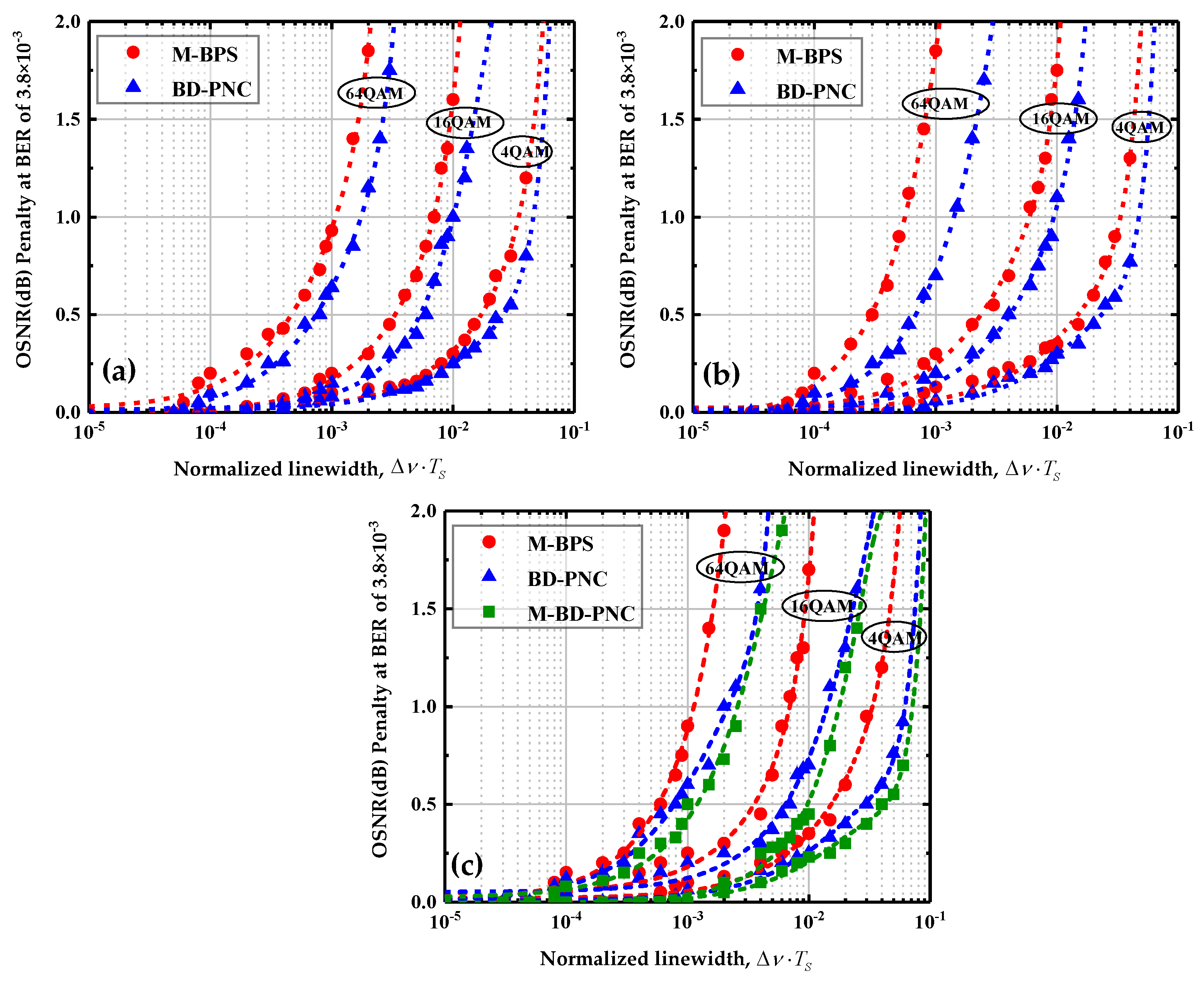
Supposing that the pre-forward error correction BER should be lower than
for hard-decision forward error correction (HD-FEC) [
43], the performance of these PNC algorithms is investigated at the BER target limit.
Figure 7a–c show the OSNR penalty as a function of the linewidth and symbol duration product
using M-BPS and the proposed algorithms for CO-FBMC/OQAM BTB transmission system with 256, 512, and 1024 subcarriers, respectively. The optimal numbers of test phases in the related M-BPS scheme are chosen as 16/32/64 for 4/16/64-QAM modulation order, respectively [
28]. When the number of subcarriers is 256 or 512, the length
L of DCT basis is set to 2. The length of DCT basis
L is selected as 10 with total number of subcarriers
M = 1024. The parameter
δ is set to 1.8 in this paper. The OSNR penalty is defined as the difference between the required OSNR for a BER of
at a current laser linewidth and zero laser linewidth in CO-FBMC/OQAM systems, where the PNC algorithm is used in the former, and none of the PNC methods is applied in the PN free system in the latter. When no PN exists in the system, the reference OSNRs for 4/16/64-QAM 30 Gbaud signal at the HD-FEC threshold are ∼4.4, ∼10, and∼16.8 dB, respectively. For comparison, an acceptable maximum of 1 dB OSNR penalty is regarded as a threshold value [
27].
On the whole, the proposed algorithm provides significantly better performance than M-BPS. In
Figure 7a, at 1 dB OSNR penalty threshold, with the number of subcarriers
M = 256, the M-BPS achieves a
tolerance of
,
, and
for 4/16/64-QAM 30 Gbaud signal, respectively. While using the proposed BD-PNC method, under 1 dB OSNR penalty constraint, the maximum
that can be achieved for 4/16/64-QAM are
,
, and
, respectively. With the increase in the QAM modulation order, the difference between the performance of the two methods is more remarkable. At higher order modulation format, the ICI effect becomes stronger, and the BD-PNC scheme achieves more significant results than M-BPS. In
Figure 7b, at
M = 512, M-BPS and BD-PNC achieve a
tolerance of
and
for 64-QAM 30 Gbaud signal, respectively.
The studies focus on the investigation of the proposed BD-PNC algorithm’s performance with the number of subcarriers
M = 1024. As a comparison, the performance of the M-BD-PNC algorithm is also evaluated in the 30 GBaud BTB CO-FBMC/OQAM systems with 1024 subcarriers. In
Figure 7c, the M-BD-PNC achieves a better
tolerance than the BD-PNC. This is because the column full-rank condition is easily satisfied in the M-BD-PNC scheme, and its performance benefits from the enhanced estimation accuracy of DCT coefficients by the LS method. Moreover, the M-BD-PNC has a lower CC than the corresponding BD-PNC algorithm, and a detailed analysis of their CC will be described at the end of the section. With a large number of subcarriers, the ICI components in PN have a huge negative impact on the performance. With the ICI effect mitigated, the proposed algorithms offer a significantly better performance compared to the M-BPS under the same QAM modulation order. In particular, the BD-PNC and M-BD-PNC achieve tolerated linewidth and symbol duration products of
and
for 64-QAM 30 Gbaud signal, while the M-BPS can only achieve a
tolerance of
.
Finally, we compare the CC of M-BPS, the proposed BD-PNC, and M-BD-PNC algorithms in terms of the number of real multiplications in one FBMC/OQAM block. Since the M-BD-PNC method involves several neighboring FBMC/OQAM blocks, its CC is evaluated as the average CC per block. As shown in
Table 2, the CC of the proposed BD-PNC and M-BD-PNC algorithms are compared. According to the block diagram in
Figure 2, the CC of the proposed BD-PNC involves the CC of its four DSP steps, including M-BPS, time-domain PNC, calculation of DCT coefficients, and final compensation. The CC of the M-BPS method is given by
O(2
MY) [
28]. The time-domain PNC model is described by Equation (19), and its CC is
O(
LMlog
2M+
LKM). For the BD-PNC, the DCT coefficients are calculated in Equation (24), and its CC is given by
O(8
L3 + 8
ZnL2 + 2
ZnL), where
Zn is the total number of pre-estimated transmitted signals in the
nth FBMC/OQAM block, while in the M-BD-PNC, the DCT coefficients are obtained by Equations (30) and (34), and real multiplications needed in these equations are
O(8
L3/3 + 8
ZnL2 + 2
ZnL + 2
L2/3). For BD-PNC and M-BD-PNC, the final PNC is completed by using Equation (22), and its CC is
O(2
ML). In order to compare the CC of these algorithms directly, several simulations are carried out to investigate the average value of
Zn at a BER of
. In this case, the average value of
Zn is shown in
Table 3. Consequently, the required real multiplication numbers per block are counted by type, as shown in
Table 4. As a comparison, when all the data after CPE compensation participate in the pre-decision (
δ = 0), the required real multiplication numbers of BD-PNC or M-BD-PNC is provided in parentheses. It is observed that the optimization of the parameter
δ in the pre-decision process results in a remarkable decrease in complexity. Furthermore, it is clear that the CC of proposed BD-PNC or M-BD-PNC is not significantly higher than M-BPS, and their CC is less than four times higher than that of M-BPS for 1024 subcarriers 64-QAM 30 Gbaud signals. Nevertheless, the proposed algorithms have a great advantage over M-BPS in terms of the PNC performance. The CC of M-BD-PNC is slightly lower than that of BD-PNC, and its performance is even superior to the BD-PNC algorithm. Therefore, at
M = 1024, the proposed M-BD-PNC should be the first choice.

 ,
, 


