Optical OFDM for SiPM-Based Underwater Optical Wireless Communication Links


Abstract
1. Introduction
2. High Spectral Efficiency State-of-the-Art Techniques
3. General Assumptions
3.1. Modeling Received Optical Power
3.2. SiPM Modeling
4. Optical OFDM Signaling
4.1. Classical O-OFDM Schemes
4.2. Improving Spectral Efficiency with Respect to DCO-OFDM
5. Description of the Considered Signaling Schemes
5.1. DCO-OFDM
5.2. ACO-OFDM
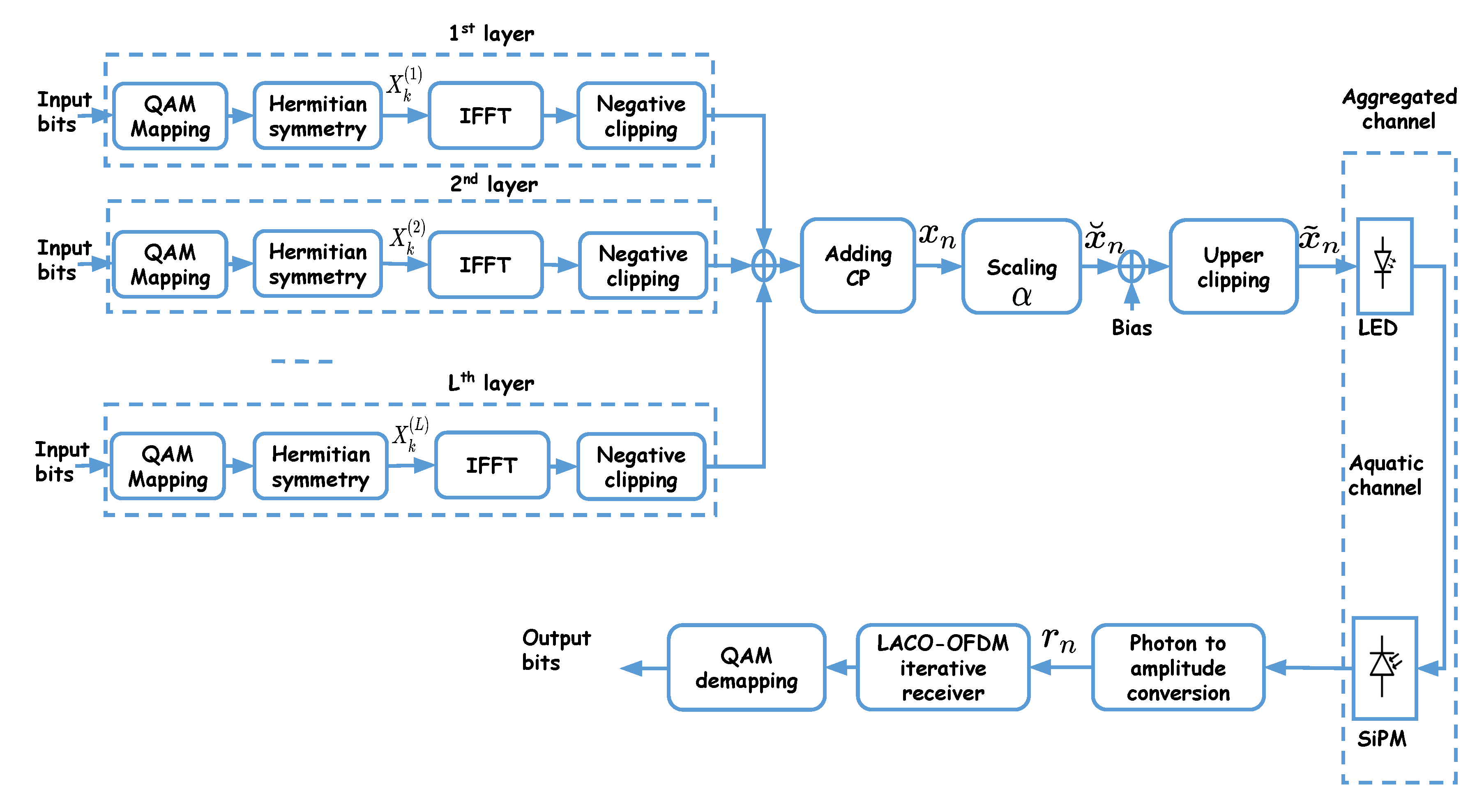
5.3. LACO-OFDM
- For the first layer, ACO-OFDM signaling is used where symbols and their complex conjugates (according to the Hermitian symmetry requirement) are sent on the odd sub-carriers with . These are then transformed into time domain after N point IFFT.
- For the subsequent layers, the corresponding frames are mapped onto the remaining even sub-carriers.
- For the second layer, symbols and their complex conjugates are sent on sub-carriers with ; they are transformed into time domain after N-point IFFT, while the amplitudes of the remaining sub-carriers are set to zero.
- In general, for the layer, , symbols and their complex conjugates are sent on sub-carriers with . Then, setting the amplitudes of the remaining sub-carriers to zero, they are transformed into time domain after N-point IFFT.
- Use detected symbols in the previous layers to obtain the corresponding time-domain signals , as it is done at the Tx;
- Calculate their contribution in the received signal;
- Subtract the resulting signals from ;
- Use the same steps as for the first layer on the (partially) distortion-removed signal to obtain .
5.4. Computational Complexity
5.5. Adapting the Signal Amplitude to the LED DR
6. Performance Study of the UWOC Link
6.1. Parameter Specification
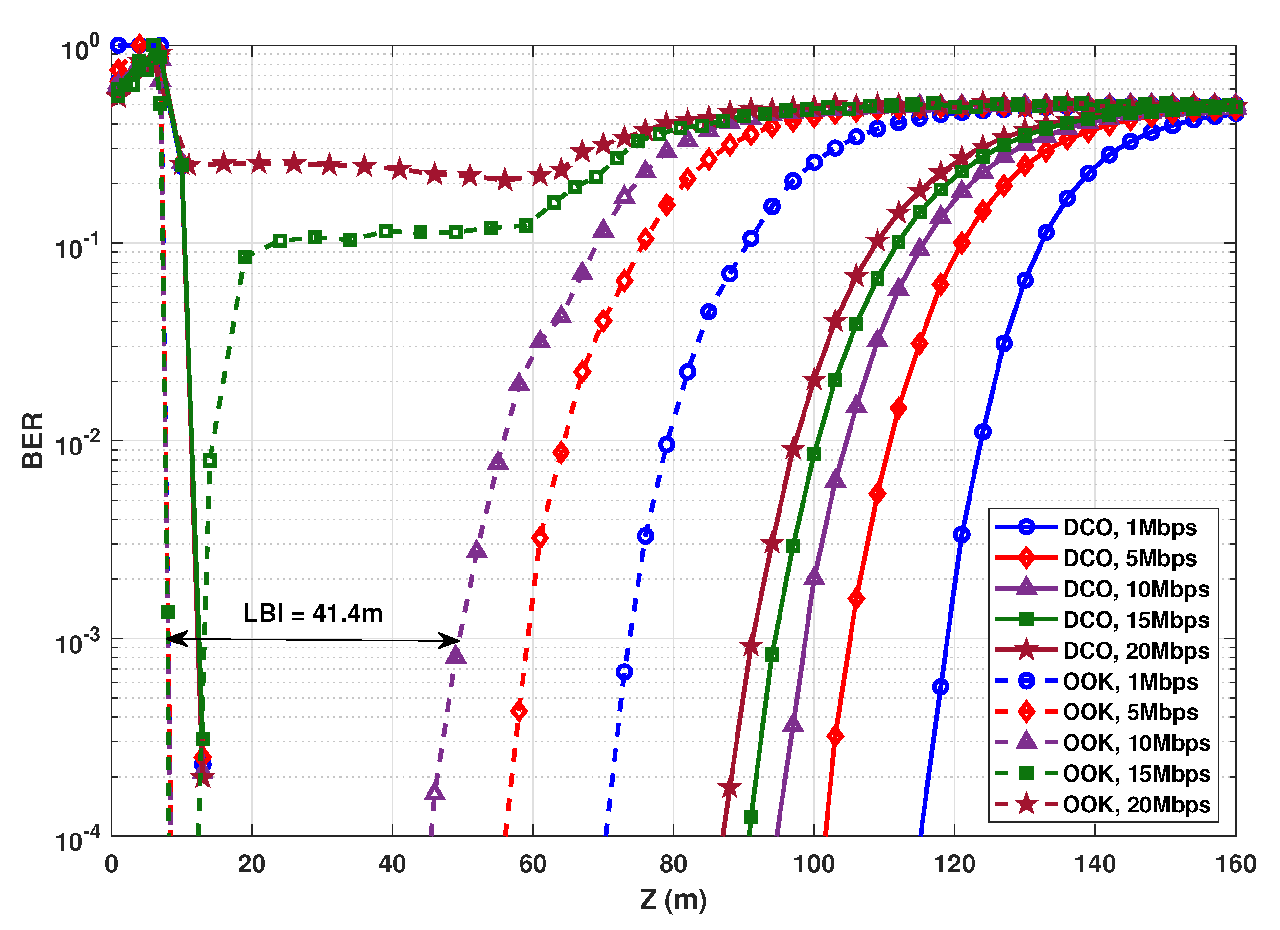
6.2. Comparison with OOK
6.3. Clipping Effect on the Link Performance
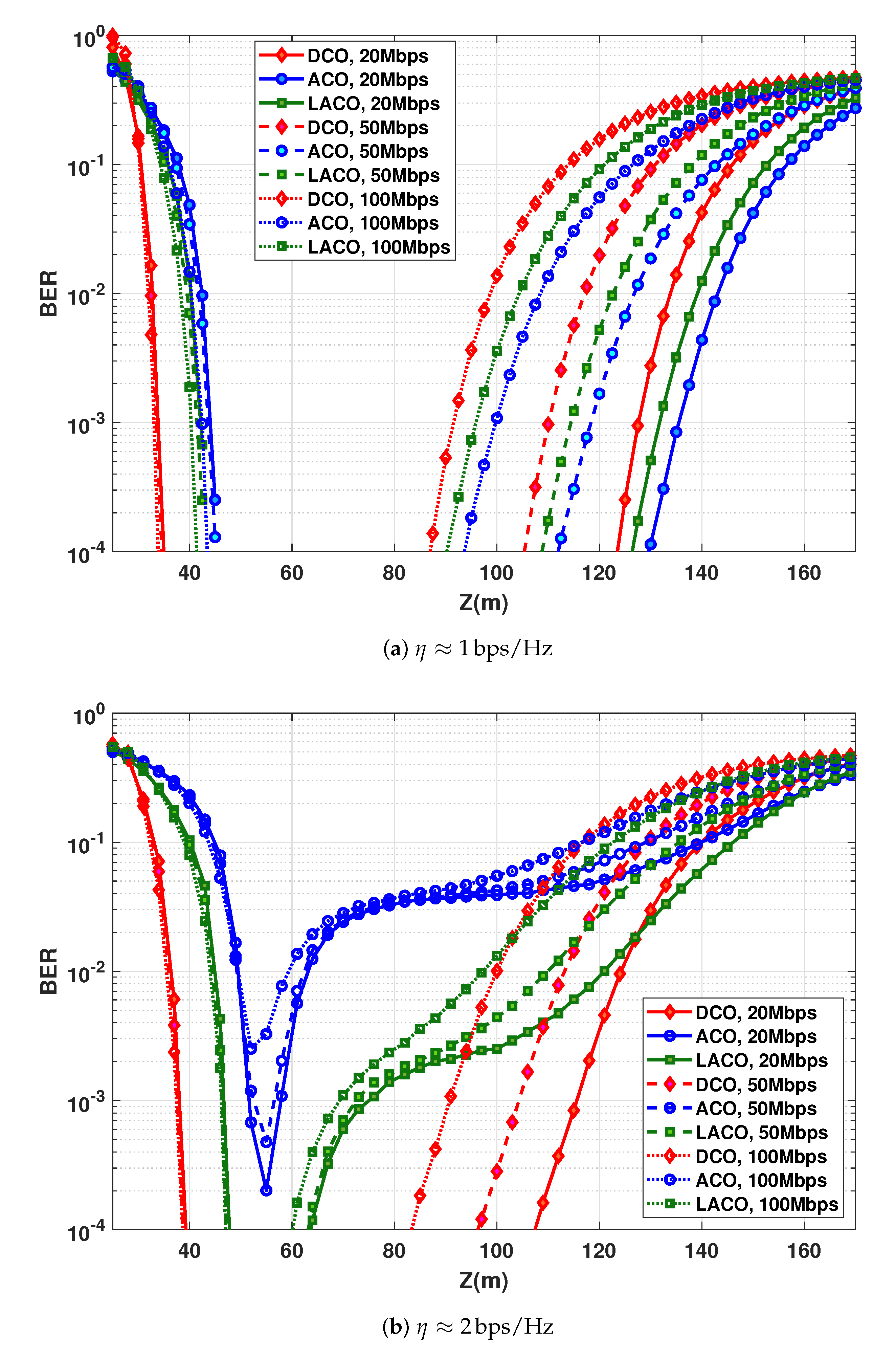
6.4. Impact of Data Rate and Transmit Power
6.5. Relaxing the Transmit Power Constraint
6.6. Impact of QAM Constellation Size
6.7. Increasing Link Span Using Multiple LEDs
6.8. Impact of Bias Selection for DCO-OFDM
7. Discussions and Conclusions
7.1. Main Conclusions
7.2. Considered Assumptions
Author Contributions
Funding
Acknowledgments
Conflicts of Interest
Appendix A. Calculating the Optimal Bias for DCO-OFDM
Appendix B. Performance of DCO-OFDM with Optimal and Non-Optimal DC Bias

Appendix C. Required Precision for Calculating the Optimal Bias for DCO-OFDM


References
- Hanson, F.; Radic, S. High bandwidth underwater optical communication. Appl. Opt. 2008, 47, 277–283. [Google Scholar] [CrossRef]
- Cochenour, B.M.; Mullen, L.J.; Laux, A.E. Characterization of the Beam-Spread Function for Underwater Wireless Optical Communications Links. IEEE J. Ocean. Eng. 2008, 33, 513–521. [Google Scholar] [CrossRef]
- Khalighi, M.A.; Gabriel, C.; Hamza, T.; Bourennane, S.; Léon, P.; Rigaud, V. Underwater Wireless Optical Communication; Recent Advances and Remaining Challenges. In Proceedings of the 2014 16th International Conference on Transparent Optical Networks (ICTON), Graz, Austria, 6–10 July 2014; pp. 1–4. [Google Scholar]
- Khalighi, M.A.; Gabriel, C.J.; Pessoa, L.M.; Silva, B. Visible Light Communications: Theory and Applications; Underwater Visible Light Communications, Channel Modeling and System Design; CRC-Press: Boca Raton, FL, USA, 2017; pp. 337–372. [Google Scholar]
- Sun, X.; Kang, C.H.; Kong, M.; Alkhazragi, O.; Guo, Y.; Ouhssain, M.; Weng, Y.; Jones, B.H.; Ng, T.K.; Ooi, B.S. A Review on Practical Considerations and Solutions in Underwater Wireless Optical Communication. J. Light. Technol. 2020, 38, 421–431. [Google Scholar] [CrossRef]
- Khalighi, M.A.; Hamza, T.; Bourennane, S.; Léon, P.; Opderbecke, J. Underwater Wireless Optical Communications Using Silicon Photo-multipliers. IEEE Photonics J. 2017, 9, 1–10. [Google Scholar] [CrossRef]
- Li, Y.; Safari, M.; Henderson, R.; Haas, H. Nonlinear Distortion in SPAD-Based Optical OFDM Systems. In Proceedings of the Global Communications Conference (GLOBECOM), Workshop on Optical Wireless Communications, San Diego, CA, USA, 6–10 December 2015; pp. 1–6. [Google Scholar]
- Khalighi, M.A.; Long, S.; Bourennane, S.; Ghassemlooy, Z. PAM and CAP-based Transmission Schemes for Visible-Light Communications. IEEE Access 2017, 5, 27002–27013. [Google Scholar] [CrossRef]
- Khalighi, M.; Akhouayri, H.; Hranilovic, S. Silicon-Photomultiplier-Based Underwater Wireless Optical Communication Using Pulse-Amplitude Modulation. IEEE J. Ocean. Eng. 2020, 45, 1611–1621. [Google Scholar] [CrossRef]
- Hamza, T.; Khalighi, M. On Limitations of Using Silicon Photo-Multipliers for Underwater Wireless Optical Communications. In Proceedings of the 2019 2nd West Asian Colloquium on Optical Wireless Communications (WACOWC), Tehran, Iran, 27–28 April 2019; pp. 74–79. [Google Scholar]
- Nakamura, K.; Mizukoshi, I.; Hanawa, M. Optical wireless transmission of 405 nm, 1.45 Gbit/s optical IM/DD-OFDM signals through a 4.8 m underwater channel. Opt. Express 2015, 23, 1558–1566. [Google Scholar] [CrossRef] [PubMed]
- Oubei, H.M.; Duran, J.R.; Janjua, B.; Wang, H.Y.; Tsai, C.T.; Chi, Y.C.; Ng, T.K.; Kuo, H.C.; He, J.H.; Alouini, M.S.; et al. 4.8 Gbit/s 16-QAM-OFDM transmission based on compact 450-nm laser for underwater wireless optical communication. Opt. Express 2018, 26, 23397–23410. [Google Scholar]
- Goldsmith, A. Wireless Communications; Cambridge University Press: Cambridge, UK, 2005. [Google Scholar]
- Xu, J.; Song, Y.; Yu, X.; Lin, A.; Kong, M.; Han, J.; Deng, N. Underwater wireless transmission of high-speed QAM-OFDM signals using a compact red-light laser. Opt. Express 2016, 24, 8097–8109. [Google Scholar] [CrossRef]
- Wu, T.C.; Chi, Y.C.; Wang, H.Y.; Tsai, C.T.; Lin, G.R. Blue Laser Diode Enables Underwater Communication at 12.4 Gbps. Sci. Rep. 2017, 7, 1–10. [Google Scholar] [CrossRef]
- Xu, J.; Kong, M.; Lin, A.; Song, Y.; Yu, X.; Qu, F.; Han, J.; Deng, N. OFDM-based broadband underwater wireless optical communication system using a compact blue LED. Opt. Commun. 2016, 369, 100–105. [Google Scholar] [CrossRef]
- Chen, Y.; Kong, M.; Ali, T.; Wang, J.; Sarwar, R.; Han, J.; Guo, C.; Sun, B.; Deng, N.; Xu, J. 26 m/5.5 Gbps air-water optical wireless communication based on an OFDM-modulated 520-nm laser diode. Opt. Express 2017, 25, 14760–14765. [Google Scholar] [CrossRef] [PubMed]
- Wang, J.; Yang, X.; Lv, W.; Yu, C.; Wu, J.; Zhao, M.; Qu, F.; Xu, Z.; Han, J.; Xu, J. Underwater wireless optical communication based on multi-pixel photon counter and OFDM modulation. Opt. Commun. 2019, 451, 181–185. [Google Scholar] [CrossRef]
- Baykal, Y. Scintillations of LED sources in oceanic turbulence. Appl. Opt. 2016, 55, 8860–8863. [Google Scholar] [CrossRef]
- Zedini, E.; Oubei, H.M.; Kammoun, A.; Hamdi, M.; Ooi, B.S.; Alouini, M.S. Unified Statistical Channel Model for Turbulence-Induced Fading in Underwater Wireless Optical Communication Systems. IEEE Trans. Commun. 2019, 67, 2893–2907. [Google Scholar] [CrossRef]
- Ghassemlooy, Z.; Alves, L.N.; Zvànovec, S.; Khalighi, M.A. (Eds.) Visible Light Communications: Theory and Applications; CRC-Press: Boca Raton, FL, USA, 2017. [Google Scholar]
- Giles, J.W.; Bankman, I.N. Underwater Optical Communication Systems. Part 2: Basic Design considerations. In Proceedings of the MILCOM 2005—2005 IEEE Military Communications Conference, Atlantic City, NJ, USA, 17–20 October 2005; pp. 1700–1705. [Google Scholar]
- Sarbazi, E.; Safari, M.; Haas, H. Statistical Modeling of Single-Photon Avalanche Diode Receivers for Optical Wireless Communications. IEEE Trans. Commun. 2018, 66, 4043–4058. [Google Scholar] [CrossRef]
- IEEE Standard for Information Technology—Telecommunications and Information Exchange Between Systems Local and Metropolitan Area Networks–Specific Requirements—Part 11: Wireless LAN Medium Access Control (MAC) and Physical Layer (PHY) Specifications Amendment: Light Communications. 2018. Available online: https://standards.ieee.org/project/802_11bb.html (accessed on 23 October 2020).
- Wang, Q.; Qian, C.; Guo, X.; Wang, Z.; Cunningham, D.G.; White, I.H. Layered ACO-OFDM for intensity-modulated direct-detection optical wireless transmission. Opt. Express 2015, 23, 12382–12393. [Google Scholar] [CrossRef]
- Armstrong, J. OFDM for Optical Communications. IEEE/OSA J. Light. Technol. 2009, 27, 189–204. [Google Scholar] [CrossRef]
- Fernando, N.; Hong, Y.; Viterbo, E. Flip-OFDM for Unipolar Communication Systems. IEEE Trans. Commun. 2012, 60, 3726–3733. [Google Scholar] [CrossRef]
- Tsonev, D.; Sinanovic, S.; Haas, H. Novel Unipolar Orthogonal Frequency Division Multiplexing (U-OFDM) for Optical Wireless. In Proceedings of the 2012 IEEE 75th Vehicular Technology Conference (VTC Spring), Yokohama, Japan, 6–9 May 2012; pp. 1–5. [Google Scholar]
- Tsonev, D.; Haas, H. Avoiding spectral efficiency loss in unipolar OFDM for optical wireless communication. In Proceedings of the 2014 IEEE International Conference on Communications (ICC), Sydney, NSW, Australia, 10–14 June 2014; pp. 3336–3341. [Google Scholar]
- Islim, M.S.; Tsonev, D.; Haas, H. On the superposition modulation for OFDM-based optical wireless communication. In Proceedings of the 2015 IEEE Global Conference on Signal and Information Processing (GlobalSIP), Orlando, FL, USA, 14–16 December 2015; pp. 1022–1026. [Google Scholar]
- Lee, S.C.J.; Randel, S.; Breyer, F.; Koonen, A.M.J. PAM-DMT for Intensity-Modulated and Direct-Detection Optical Communication Systems. IEEE Photonics Technol. Lett. 2009, 21, 1749–1751. [Google Scholar] [CrossRef]
- Tsonev, D.; Videv, S.; Haas, H. Unlocking Spectral Efficiency in Intensity Modulation and Direct Detection Systems. IEEE J. Sel. Areas Commun. 2015, 33, 1758–1770. [Google Scholar] [CrossRef]
- Dissanayake, S.D.; Armstrong, J. Comparison of ACO-OFDM, DCO-OFDM and ADO-OFDM in IM/DD Systems. J. Light. Technol. 2013, 31, 1063–1072. [Google Scholar] [CrossRef]
- Ranjha, B.; Kavehrad, M. Hybrid Asymmetrically Clipped OFDM-Based IM/DD Optical Wireless System. IEEE/OSA J. Opt. Commun. Netw. 2014, 6, 387–396. [Google Scholar] [CrossRef]
- Li, B.; Feng, S.; Xu, W. Spectrum-efficient hybrid PAM-DMT for intensity-modulated optical wireless communication. Opt. Express 2020, 28, 12621–12637. [Google Scholar] [CrossRef]
- Lowery, A.J. Comparisons of spectrally-enhanced asymmetrically-clipped optical OFDM systems. Opt. Express 2016, 24, 3950–3966. [Google Scholar] [CrossRef]
- Sun, Y.; Yang, F.; Gao, J. Comparison of Hybrid Optical Modulation Schemes for Visible Light Communication. IEEE Photonics J. 2017, 9, 1–13. [Google Scholar] [CrossRef]
- Sun, Y.; Yang, F.; Cheng, L. An Overview of OFDM-Based Visible Light Communication Systems From the Perspective of Energy Efficiency Versus Spectral Efficiency. IEEE Access 2018, 6, 60824–60833. [Google Scholar] [CrossRef]
- Safari, M. Efficient Optical Wireless Communication in the Presence of Signal-Dependent Noise. In Proceedings of the 2015 IEEE International Conference on Communication Workshop (ICCW), London, UK, 8–12 June 2015; pp. 1387–1391. [Google Scholar]
- Armstrong, J.; Schmidt, B.J.C. Comparison of Asymmetrically Clipped Optical OFDM and DC-Biased Optical OFDM in AWGN. IEEE Commun. Lett. 2008, 12, 343–345. [Google Scholar] [CrossRef]
- Zhang, X.; Wang, Q.; Zhang, R.; Chen, S.; Hanzo, L. Performance Analysis of Layered ACO-OFDM. IEEE Access 2017, 5, 18366–18381. [Google Scholar] [CrossRef]
- Bai, R.; Hranilovic, S. Absolute Value Layered ACO-OFDM for Intensity-Modulated Optical Wireless Channels. IEEE Trans. Commun. 2020. In Press. [Google Scholar] [CrossRef]
- NICHIA Corporation. Specifications for blue LED: NSPB510AS. Available online: http://www.nichia.co.jp (accessed on 23 October 2020).
- Tsonev, D.; Sinanovic, S.; Haas, H. Complete Modeling of Nonlinear Distortion in OFDM-Based Optical Wireless Communication. IEEE/OSA J. Light. Technol. 2013, 31, 3064–3076. [Google Scholar] [CrossRef]
- Long, S.; Khalighi, M. Advantage of CAP Signaling for VLC Systems Under Non-Linear LED Characteristics. In Proceedings of the 2019 2nd West Asian Colloquium on Optical Wireless Communications (WACOWC), Tehran, Iran, 27–28 April 2019; pp. 21–25. [Google Scholar]
- Jiang, R.; Wang, Q.; Wang, F.; Dai, L.; Wang, Z. An optimal scaling scheme for DCO-OFDM based visible light communications. Opt. Commun. 2015, 356, 136–140. [Google Scholar] [CrossRef]
- Dimitrov, S.; Haas, H. Optimum Signal Shaping in OFDM-Based Optical Wireless Communication Systems. In Proceedings of the 2012 IEEE Vehicular Technology Conference (VTC Fall), Quebec City, QC, Canada, 3–6 September 2012; pp. 1–5. [Google Scholar]
- Zhang, M.; Zhang, Z. An Optimum DC-Biasing for DCO-OFDM System. IEEE Commun. Lett. 2014, 18, 1351–1354. [Google Scholar] [CrossRef]
- Hamamatsu. MPPC Modules Data-Sheet, GA Types, C13366 Series. Available online: https://www.hamamatsu.com/resources/pdf/ssd/c13366-1350ga_etc_kacc1228e.pdf (accessed on 23 October 2020).
- Xu, F.; Khalighi, M.A.; Bourennane, S. Impact of Different Noise Sources on the Performance of PIN- and APD-based FSO Receivers. In Proceedings of the 11th International Conference on Telecommunications, Graz, Austria, 15–17 June 2011; pp. 211–218. [Google Scholar]
- Hamza, T.; Khalighi, M.A.; Bourennane, S.; Léon, P.; Opderbecke, J. Investigation of Solar Noise Impact on the Performance of Underwater Wireless Optical Communication Links. Opt. Express 2016, 24, 25832–25845. [Google Scholar] [CrossRef] [PubMed]
- B-Series Fast, Blue-Sensitive Silicon Photomultiplier Sensors datasheet; SensL. (Rev. 3.1, Nov. 2015). 2013. Available online: http://www.sensl.com/downloads/ds/DS-MicroBseries.pdf (accessed on 23 October 2020).
- Léon, P.; Roland, F.; Brignone, L.; Opderbecke, J.; Greer, J.; Khalighi, M.A.; Hamza, T.; Bourennane, S.; Bigand, M. A New Underwater Optical Modem based on Highly Sensitive Silicon Photo-Multipliers. In Proceedings of the OCEANS 2017, Aberdeen, UK, 19–22 June 2017; pp. 1–6. [Google Scholar]


| Tx (LED) | Wavelength | 470 nm |
| 3 dB cut-off frequency | 10 MHz | |
| Lambertian order m | 45 | |
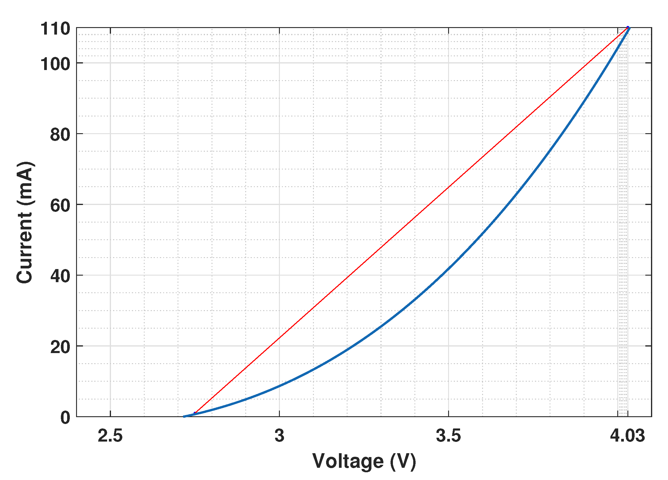
| I-V parameters (, ; , ) | ( V, V; 1 mA, 110 mA) | |
| Channel | Diffuse attenuation coefficient K | m−1 |
| Rx (SiPM) | Photon Detection Efficiency, | |
| Surface Area, | 9 mm2 | |
| Dark Current Rate, | 25 kHz | |
| Dead Time, | ns | |
| No. of SPADs, | 3600 | |
| Cross-Talk Prob., | ||
| After-Pulsing Prob., | % | |
| 3 dB Cut-Off Frequency | 4 MHz |
| (Mbps) | LBI (m) | (m) | |
|---|---|---|---|
| DCO | 1 | ||
| 5 | 105 | ||
| 10 | |||
| 15 | |||
| 20 | |||
| OOK | 1 | ||
| 5 | |||
| 10 | |||
| 15 | |||
| 20 | - | - |
| (Mbps) | LBI (m) | (m) | |
|---|---|---|---|
| DCO | 20 | ||
| 50 | |||
| 100 | |||
| ACO | 20 | ||
| 50 | 73 | ||
| 100 | |||
| LACO | 20 | ||
| 50 | |||
| 100 | 53 |
| (Mbps) | LBI (m) | (m) | |
|---|---|---|---|
| DCO | 20 | 81 | 95 |
| 50 | |||
| 100 | 48 | ||
| ACO | 20 | ||
| 50 | 73 | ||
| 100 | |||
| LACO | 20 | ||
| 50 | |||
| 100 |
| mW | mW | ||||
|---|---|---|---|---|---|
| (Mbps) | LBI (m) | (m) | LBI (m) | (m) | |
| DCO | 20 | ||||
| 50 | |||||
| 100 | 38 | ||||
| ACO | 20 | ||||
| 50 | − | − | |||
| 100 | − | − | |||
| LACO | 20 | ||||
| 50 | 42 | ||||
| 100 | 34 | ||||
| bps/Hz | bps/Hz | ||||
|---|---|---|---|---|---|
| (Mbps) | LBI (m) | (m) | LBI (m) | (m) | |
| DCO | 20 | ||||
| 50 | |||||
| 100 | |||||
| ACO | 20 | ||||
| 50 | |||||
| 100 | − | − | |||
| LACO | 20 | ||||
| 50 | |||||
| 100 | 23 | ||||
Publisher’s Note: MDPI stays neutral with regard to jurisdictional claims in published maps and institutional affiliations. |
© 2020 by the authors. Licensee MDPI, Basel, Switzerland. This article is an open access article distributed under the terms and conditions of the Creative Commons Attribution (CC BY) license (http://creativecommons.org/licenses/by/4.0/).
Share and Cite
Essalih, T.; Khalighi, M.A.; Hranilovic, S.; Akhouayri, H. Optical OFDM for SiPM-Based Underwater Optical Wireless Communication Links. Sensors 2020, 20, 6057. https://doi.org/10.3390/s20216057
Essalih T, Khalighi MA, Hranilovic S, Akhouayri H. Optical OFDM for SiPM-Based Underwater Optical Wireless Communication Links. Sensors. 2020; 20(21):6057. https://doi.org/10.3390/s20216057
Chicago/Turabian StyleEssalih, Taha, Mohammad Ali Khalighi, Steve Hranilovic, and Hassan Akhouayri. 2020. "Optical OFDM for SiPM-Based Underwater Optical Wireless Communication Links" Sensors 20, no. 21: 6057. https://doi.org/10.3390/s20216057
APA StyleEssalih, T., Khalighi, M. A., Hranilovic, S., & Akhouayri, H. (2020). Optical OFDM for SiPM-Based Underwater Optical Wireless Communication Links. Sensors, 20(21), 6057. https://doi.org/10.3390/s20216057