An fMRI Compatible Smart Device for Measuring Palmar Grasping Actions in Newborns

 ,
,  , , ,
, , ,  ,
,  ,
,  ,
,  ,
,  ,
, 
Abstract
1. Introduction
2. Basic Requirements and Components of the Smart Graspable Device
2.1. Technological and Clinical Requirements
2.2. Fiber Bragg Gratings Working Principles
2.3. Dragon Skin™ Silicones
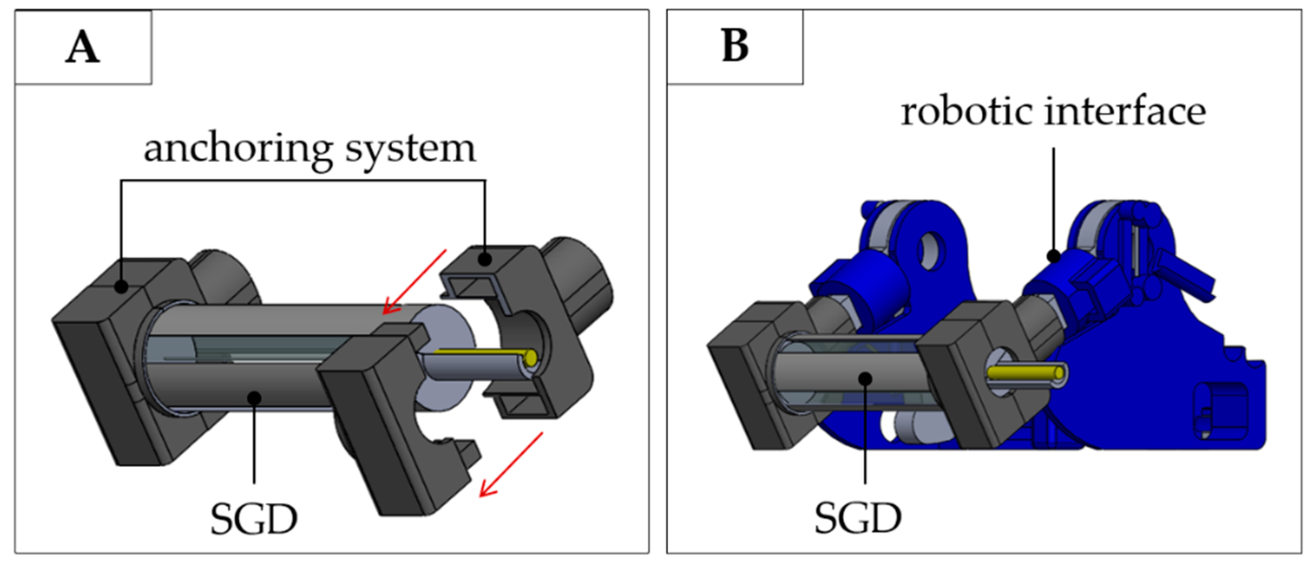
3. The Smart Graspable Device
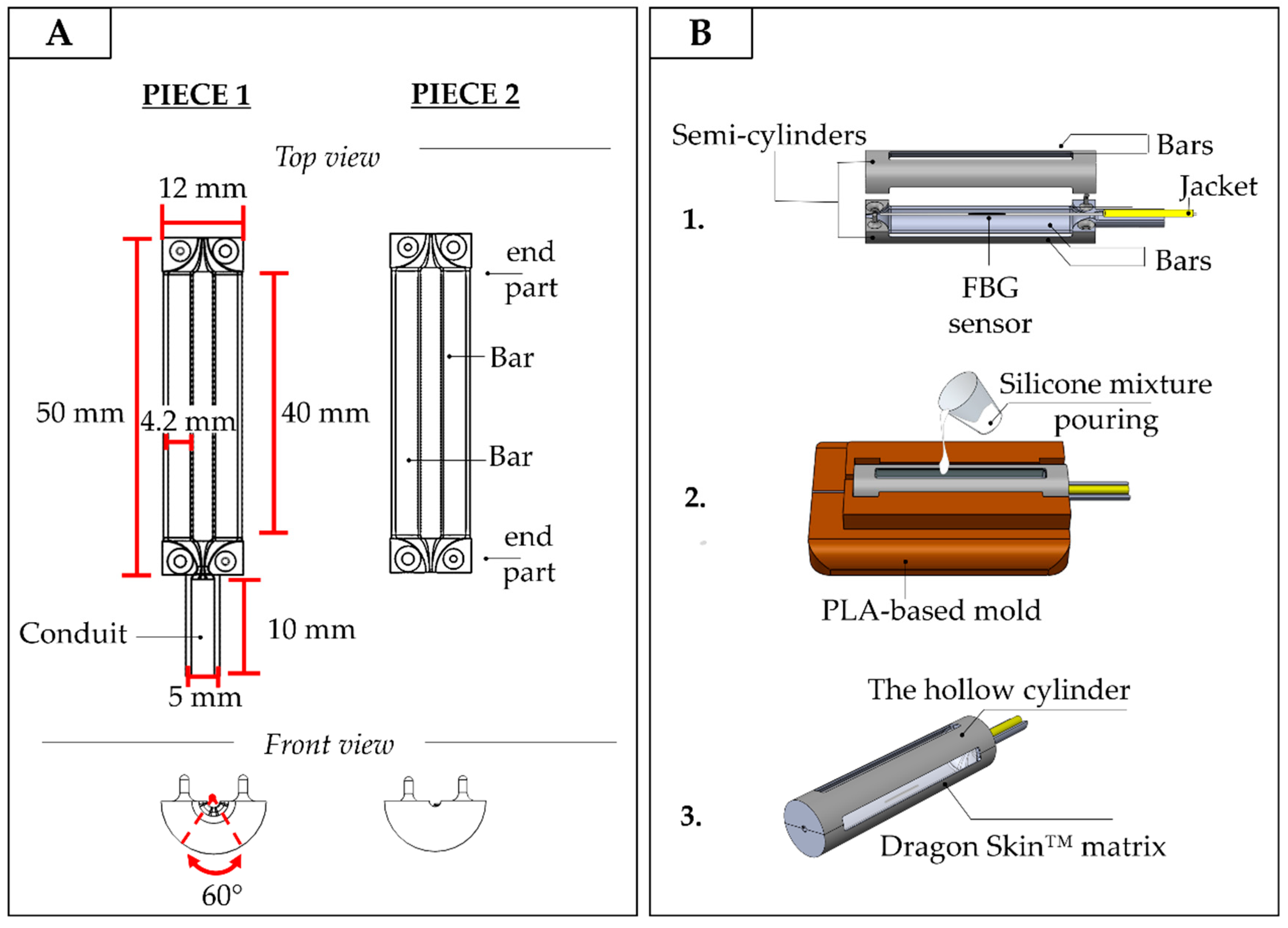
3.1. Design and Manufacturing of the Smart Graspable Device
- the optical fiber was tightly suspended inside the PLA structure by firmly gluing its two ends inside the small grooves fabricated at the center of the structure ends. This configuration utilized pre-tension to keep the FBG in a stretched state in order to improve its resolution and sensitivity (stage 1 in Figure 4B);
- the PLA structure was placed inside a mold to allow cavity filling without any silicone spilling. The silicone rubber was synthesized by mixing A and B liquid components of Dragon Skin™ polymer at a ratio of 1:1; the mix was degassed and poured into the cavity (stage 2 in Figure 4B);
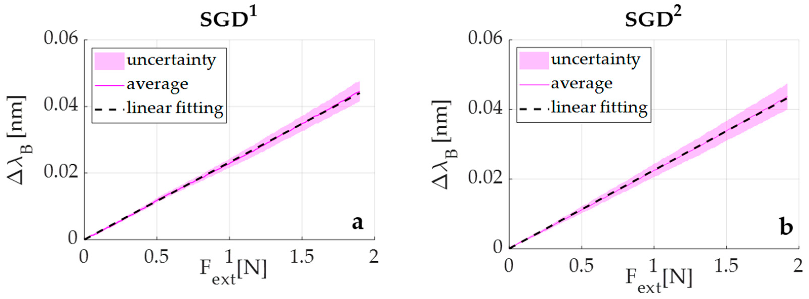
3.2. Metrological Characterization of the Smart Graspable Device
4. Experimental Validation of the Smart Graspable Device
4.1. Experimental Trial on a Newborn: Protocol and Results
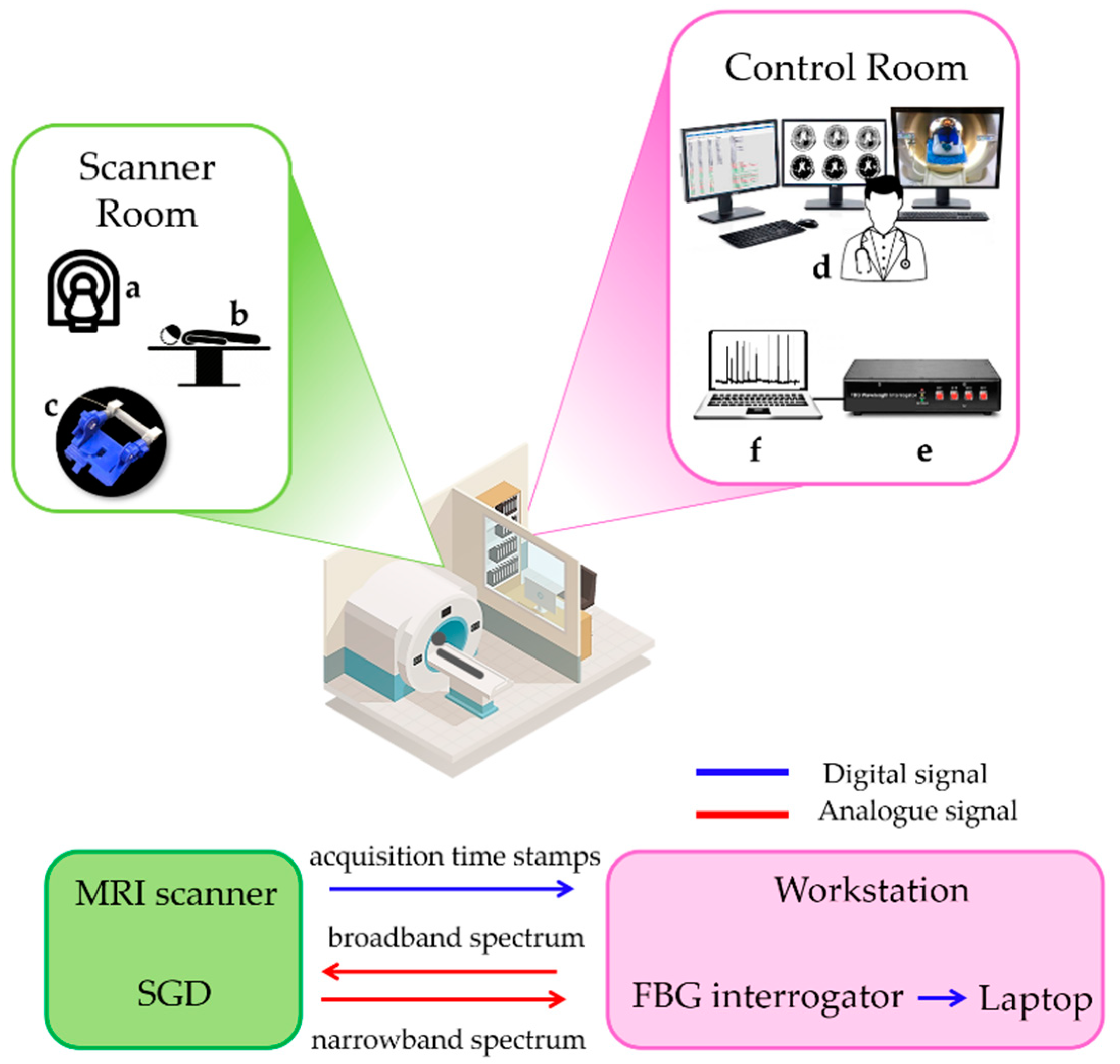
4.2. Experimental Trial on an Adult during fMRI: Protocol and Results
5. Discussion
6. Conclusions
Author Contributions
Funding
Conflicts of Interest
Ethical Statement
References
- Lejeune, F.; Audeoud, F.; Marcus, L.; Streri, A.; Debillon, T.; Gentaz, E. The manual habituation and discrimination of shapes in preterm human infants from 33 to 34+6 post-conceptional age. PLoS ONE 2010, 5, e9108. [Google Scholar] [CrossRef] [PubMed]
- Nelson, K.B.; Lynch, J.K. Stroke in newborn infants. Lancet Neurol. 2004, 3, 150–158. [Google Scholar] [CrossRef]
- Mercuri, E.; Ricci, D.; Pane, M.; Baranello, G. The neurological examination of the newborn baby. Early Hum. Dev. 2005, 81, 947–956. [Google Scholar] [CrossRef] [PubMed]
- Glick, T.H. Toward a more efficient and effective neurologic examination for the 21st century. Eur. J. Neurol. 2005, 12, 994–997. [Google Scholar] [CrossRef] [PubMed]
- Moraes, M.V.M.; Tudella, E.; Ribeiro, J.; Beltrame, T.S.; Krebs, R.J. Reliability of the M-FLEXTM: Equipment to measure palmar grasp strength in infants. Infant Behav. Dev. 2011, 34, 226–234. [Google Scholar] [CrossRef] [PubMed]
- Allievi, A.G.; Arichi, T.; Gordon, A.L.; Burdet, E. Technology-aided assessment of sensorimotor function in early infancy. Front. Neurol. 2014, 5, 197. [Google Scholar] [CrossRef] [PubMed]
- Molina, M.; Sann, C.; David, M.; Touré, Y.; Guillois, B.; Jouen, F. Active touch in late-preterm and early-term neonates. Dev. Psychobiol. 2015, 57, 322–335. [Google Scholar] [CrossRef] [PubMed]
- Allievi, A.G.; Melendez-Calderon, A.; Arichi, T.; Edwards, A.D.; Burdet, E. An fMRI compatible wrist robotic interface to study brain development in neonates. Ann. Biomed. Eng. 2013, 41, 1181–1192. [Google Scholar] [CrossRef]
- Dall’Orso, S.; Steinweg, J.; Allievi, A.G.; Edwards, A.D.; Burdet, E.; Arichi, T. Somatotopic mapping of the developing sensorimotor cortex in the preterm human brain. Cereb. Cortex 2018, 28, 2507–2515. [Google Scholar] [CrossRef]
- Stippich, C.; Freitag, P.; Kassubek, J.; Sörös, P.; Kamada, K.; Kober, H.; Scheffler, K.; Hopfengärtner, R.; Bilecen, D.; Radü, E.; et al. Motor, somatosensory and auditory cortex localization by fMRI and MEG. NeuroReport 1998, 9, 1953–1957. [Google Scholar] [CrossRef]
- Stippich, C.; Hofmann, R.; Kapfer, D.; Hempel, E.; Heiland, S.; Jansen, O.; Sartor, K. Somatotopic mapping of the human primary somatosensory cortex by fully automated tactile stimulation using functional magnetic resonance imaging. Neurosci. Lett. 1999, 277, 25–28. [Google Scholar] [CrossRef]
- Moore, C.I.; Stern, C.E.; Corkin, S.; Fischl, B.; Gray, A.C.; Rosen, B.R.; Dale, A.M. Segregation of somatosensory activation in the human rolandic cortex using fMRI. J. Neurophysiol. 2000, 84, 558–569. [Google Scholar] [CrossRef] [PubMed]
- Blatow, M.; Nennig, E.; Durst, A.; Sartor, K.; Stippich, C. fMRI reflects functional connectivity of human somatosensory cortex. Neuroimage 2007, 37, 927–936. [Google Scholar] [CrossRef] [PubMed]
- Molina, M.; Jouen, F. Weight perception in 12-month-old infants. Infant Behav. Dev. 2003, 26, 49–63. [Google Scholar] [CrossRef]
- Molina, M.; Jouen, F. Modulation of the palmar grasp behavior in neonates according to texture property. Infant Behav. Dev. 1998, 21, 659–666. [Google Scholar] [CrossRef]
- Del Maestro, M.; Cecchi, F.; Serio, S.M.; Laschi, C.; Dario, P. Sensing device for measuring infants’ grasping actions. Sens. Actuators A Phys. 2011, 165, 155–163. [Google Scholar] [CrossRef]
- Baldoli, I.; Cecchi, F.; Guzzetta, A.; Laschi, C. Sensorized graspable devices for the study of motor imitation in infants. In Proceedings of the Annual International Conference of the IEEE Engineering in Medicine and Biology Society, EMBS, Milan, Italy, 25–29 August 2015; pp. 7394–7397. [Google Scholar]
- Muhammad, T.; Lee, J.S.; Shin, Y.B.; Kim, S. A wearable device to measure the palmar grasp reflex of neonates in neonatal intensive care unit. Sens. Actuators A Phys. 2020, 304, 111905. [Google Scholar] [CrossRef]
- Cecchi, F.; Serio, S.M.; Del Maestro, M.; Laschi, C.; Sgandurra, G.; Cioni, G.; Dario, P. Design and development of “biomechatronic gym” for early detection of neurological disorders in infants. In Proceedings of the 2010 Annual International Conference of the IEEE Engineering in Medicine and Biology Society, EMBC’10, Buenos Aires, Argentina, 31 August–4 September 2010; pp. 3414–3417. [Google Scholar]
- Lo Presti, D.; Massaroni, C.; Leitao, C.S.J.; Domingues, M.F.; Sypabekova, M.; Barrera, D.; Floris, I.; Massari, L.; Oddo, C.M.; Sales, S.; et al. Fiber Bragg Gratings for medical applications and future challenges: A review. IEEE Access 2020, 8, 156863–156888. [Google Scholar] [CrossRef]
- Othonos, A. Fiber Bragg gratings. Rev. Sci. Instrum. 1997, 68, 4309–4341. [Google Scholar] [CrossRef]
- Gassert, R.; Burdet, E.; Chinzei, K. MRI-compatible robotics. IEEE Eng. Med. Biol. Mag. 2008, 27, 12–14. [Google Scholar] [CrossRef] [PubMed]
- Dempsey, M.F.; Condon, B.; Hadley, D.M. MRI safety review. Semin. Ultrasound CT MRI 2002, 23, 392–401. [Google Scholar] [CrossRef]
- Dempsey, M.F.; Condon, B. Thermal injuries associated with MRI. Clin. Radiol. 2001, 56, 457–465. [Google Scholar] [CrossRef] [PubMed]
- Krupa, K.; Bekiesińska-Figatowska, M. Artifacts in magnetic resonance imaging. Pol. J. Radiol. 2015, 80, 93–106. [Google Scholar] [PubMed]
- Hall, J.G.; Ursula, G.F.I.; Allanson, J.E. Oxford Medical Publications: Handbook of Normal Physical; Cambridge University Press: Cambridge, UK, 1989. [Google Scholar]
- Molina, M.; Jouen, F. Manual cyclical activity as an explanatory tool in neonates. Infant Behav. Dev. 2004, 27, 42–53. [Google Scholar] [CrossRef]
- Smooth-On Dragon Skin® High Performance Silicone Rubber. Available online: https://www.smooth-on.com/product-line/dragon-skin/ (accessed on 23 July 2020).
- Erdogan, T. Fiber grating spectra. J. Light. Technol. 1997, 15, 1277–1294. [Google Scholar] [CrossRef]
- Massaroni, C.; Zaltieri, M.; Lo Presti, D.; Tosi, D.; Schena, E. Fiber Bragg Grating Sensors for Cardiorespiratory Monitoring: A Review. IEEE Sens. J. 2020. [Google Scholar] [CrossRef]
- Lo Presti, D.; Carnevale, A.; D’Abbraccio, J.; Massari, L.; Massaroni, C.; Sabbadini, R.; Zaltieri, M.; Di Tocco, J.; Bravi, M.; Miccinilli, S.; et al. A multi-parametric wearable system to monitor neck movements and respiratory frequency of computer workers. Sensors 2020, 20, 536. [Google Scholar] [CrossRef]
- BSI Biological Evaluation of Medical Devices Part 10: Tests for Irritation and Skin Sensitization. Available online: https://www.iso.org/standard/40884.html (accessed on 25 August 2020).
- Mazurek, P.; Vudayagiri, S.; Skov, A.L. How to tailor flexible silicone elastomers with mechanical integrity: A tutorial review. Chem. Soc. Rev. 2019, 48, 1448–1464. [Google Scholar] [CrossRef]
- Silicone Thinner® Product Information | Smooth-On, Inc. Available online: https://www.smooth-on.com/products/silicone-thinner/ (accessed on 25 August 2020).
- ISO 7743:2011 Rubber, Vulcanized or Thermoplastic—Determination of Compression Stress-Strain Properties. Available online: https://www.iso.org/standard/72784.html (accessed on 25 August 2020).
- Willink, R.; Willink, R. Guide to the Expression of Uncertainty in Measurement. In Measurement Uncertainty and Probability; Cambridge University Press: Cambridge, UK, 2013; pp. 237–244. ISBN 9267101889. [Google Scholar]
- Jenkinson, M.; Beckmann, C.F.; Behrens, T.E.J.; Woolrich, M.W.; Smith, S.M. Review FSL. Neuroimage 2012, 62, 782–790. [Google Scholar] [CrossRef]
- Halverson, H.M. An experimental study of prehension in infants by means of systematic cinema records. Genet. Psychol. Monogr. 1931, 10, 107–286. [Google Scholar]
- Halverson, H.M. A further study of grasping. J. Gen. Psychol. 1932, 7, 34–64. [Google Scholar] [CrossRef]
- Halverson, H.M. Studies of the grasping responses of early infancy: I. Pedagog. Semin. J. Genet. Psychol. 1937, 51, 371–392. [Google Scholar] [CrossRef]
- Amiel-Tison, C.; Barrier, G.; Shnider, S.M.; Hughes, S.C.; Stefani, S.J. A new neurologic and adaptive capacity scoring system for evaluating obstetric medications in full-term newborns. Anesthesiol. J. Am. Soc. Anesthesiol. 1980, 53, S322. [Google Scholar] [CrossRef]
- Forssberg, H.; Kinoshita, H.; Eliasson, A.C.; Johansson, R.S.; Westling, G.; Gordon, A.M. Development of human precision grip—II. Anticipatory control of isometric forces targeted for object’s weight. Exp. Brain Res. 1992, 90, 393–398. [Google Scholar] [PubMed]
- Cecchi, F.; Serio, S.M.; Perego, P.; Mattoli, V.; Damiani, F.; Laschi, C.; Dario, P. A mechatronic toy for measuring infants’ grasping development. In Proceedings of the 2nd Biennial IEEE/RAS-EMBS International Conference on Biomedical Robotics and Biomechatronics, BioRob 2008, Scottsdale, AZ, USA, 19–22 October 2008; pp. 397–401. [Google Scholar]
- Cioni, G.; Bos, A.F.; Einspieler, C.; Ferrari, F.; Martijn, A.; Paolicelli, P.B.; Rapisardi, G.; Roversi, M.F.; Prechtl, H.F.R. Early neurological signs in preterm infants with unilateral intraparenchymal echodensity. Neuropediatrics 2000, 31, 240–251. [Google Scholar] [CrossRef]


Publisher’s Note: MDPI stays neutral with regard to jurisdictional claims in published maps and institutional affiliations. |
© 2020 by the authors. Licensee MDPI, Basel, Switzerland. This article is an open access article distributed under the terms and conditions of the Creative Commons Attribution (CC BY) license (http://creativecommons.org/licenses/by/4.0/).
Share and Cite
Lo Presti, D.; Dall’Orso, S.; Muceli, S.; Arichi, T.; Neumane, S.; Lukens, A.; Sabbadini, R.; Massaroni, C.; Caponero, M.A.; Formica, D.; et al. An fMRI Compatible Smart Device for Measuring Palmar Grasping Actions in Newborns. Sensors 2020, 20, 6040. https://doi.org/10.3390/s20216040
Lo Presti D, Dall’Orso S, Muceli S, Arichi T, Neumane S, Lukens A, Sabbadini R, Massaroni C, Caponero MA, Formica D, et al. An fMRI Compatible Smart Device for Measuring Palmar Grasping Actions in Newborns. Sensors. 2020; 20(21):6040. https://doi.org/10.3390/s20216040
Chicago/Turabian StyleLo Presti, Daniela, Sofia Dall’Orso, Silvia Muceli, Tomoki Arichi, Sara Neumane, Anna Lukens, Riccardo Sabbadini, Carlo Massaroni, Michele Arturo Caponero, Domenico Formica, and et al. 2020. "An fMRI Compatible Smart Device for Measuring Palmar Grasping Actions in Newborns" Sensors 20, no. 21: 6040. https://doi.org/10.3390/s20216040
APA StyleLo Presti, D., Dall’Orso, S., Muceli, S., Arichi, T., Neumane, S., Lukens, A., Sabbadini, R., Massaroni, C., Caponero, M. A., Formica, D., Burdet, E., & Schena, E. (2020). An fMRI Compatible Smart Device for Measuring Palmar Grasping Actions in Newborns. Sensors, 20(21), 6040. https://doi.org/10.3390/s20216040