Figure 1.
Design concept of lens shaping method.
Figure 1.
Design concept of lens shaping method.
Figure 2.
Lens shape based on the energy conservation law.
Figure 2.
Lens shape based on the energy conservation law.
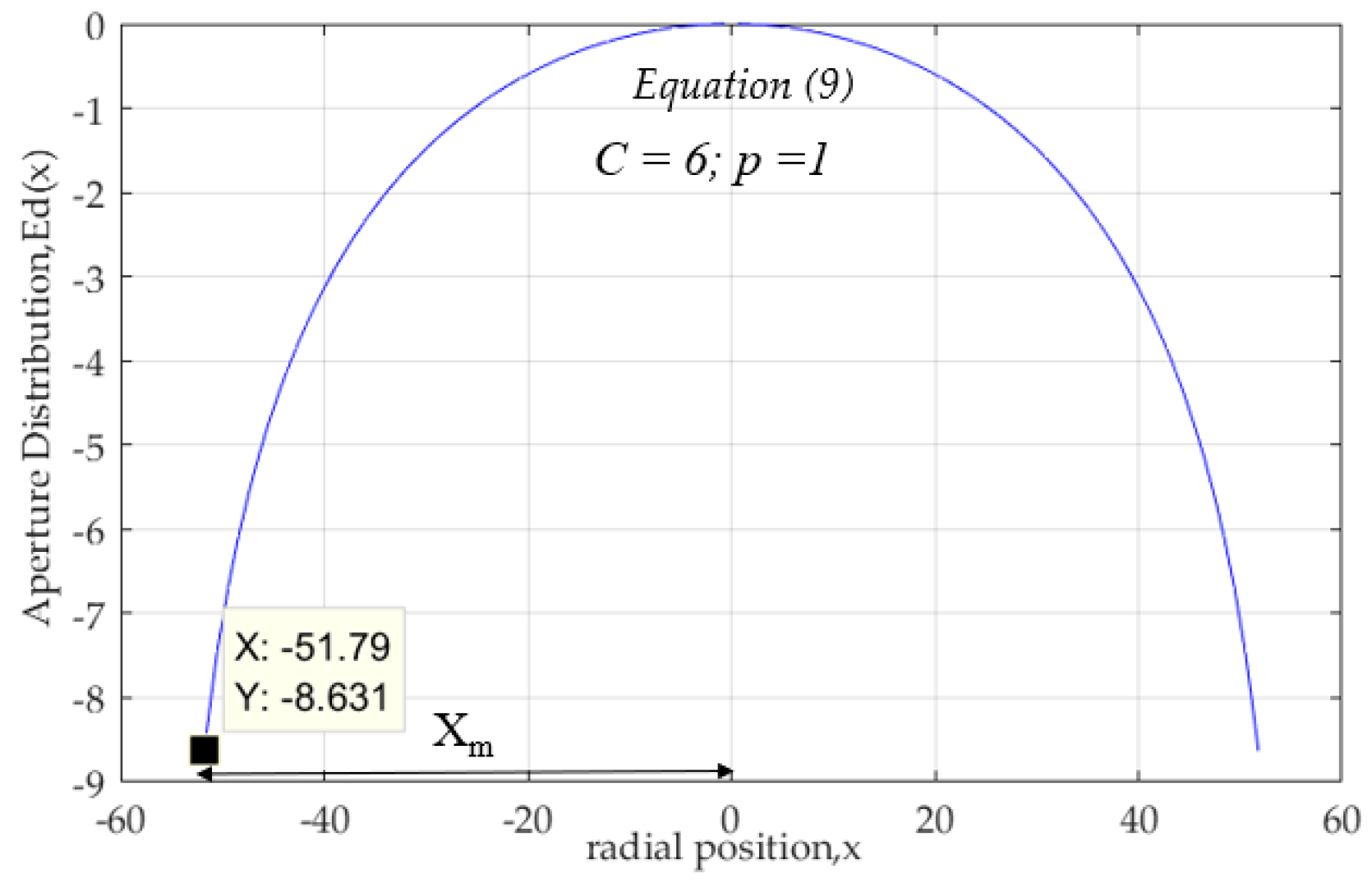
Figure 3.
Aperture distribution on x-z plane.
Figure 3.
Aperture distribution on x-z plane.
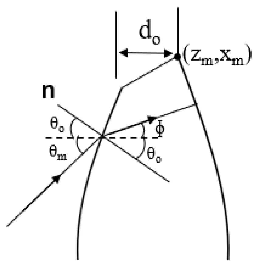
Figure 4.
Abbe’s sine condition lens.
Figure 4.
Abbe’s sine condition lens.
Figure 5.
Straight-line condition lens.
Figure 5.
Straight-line condition lens.
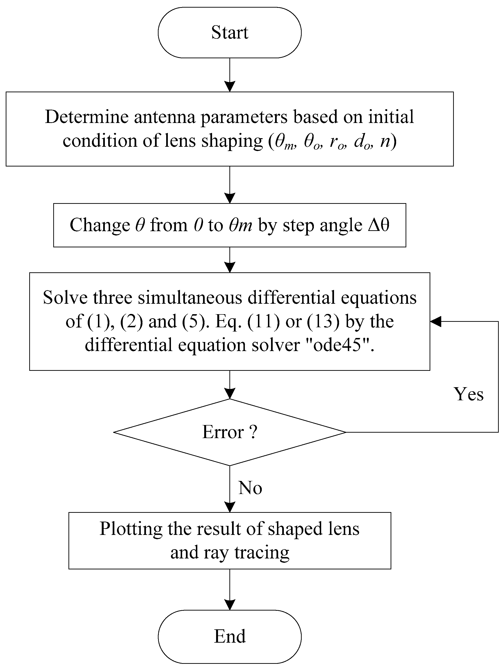
Figure 6.
Flow chart of ray tracing program for lens antenna shaping.
Figure 6.
Flow chart of ray tracing program for lens antenna shaping.
Figure 7.
Initial condition of lens shaping.
Figure 7.
Initial condition of lens shaping.
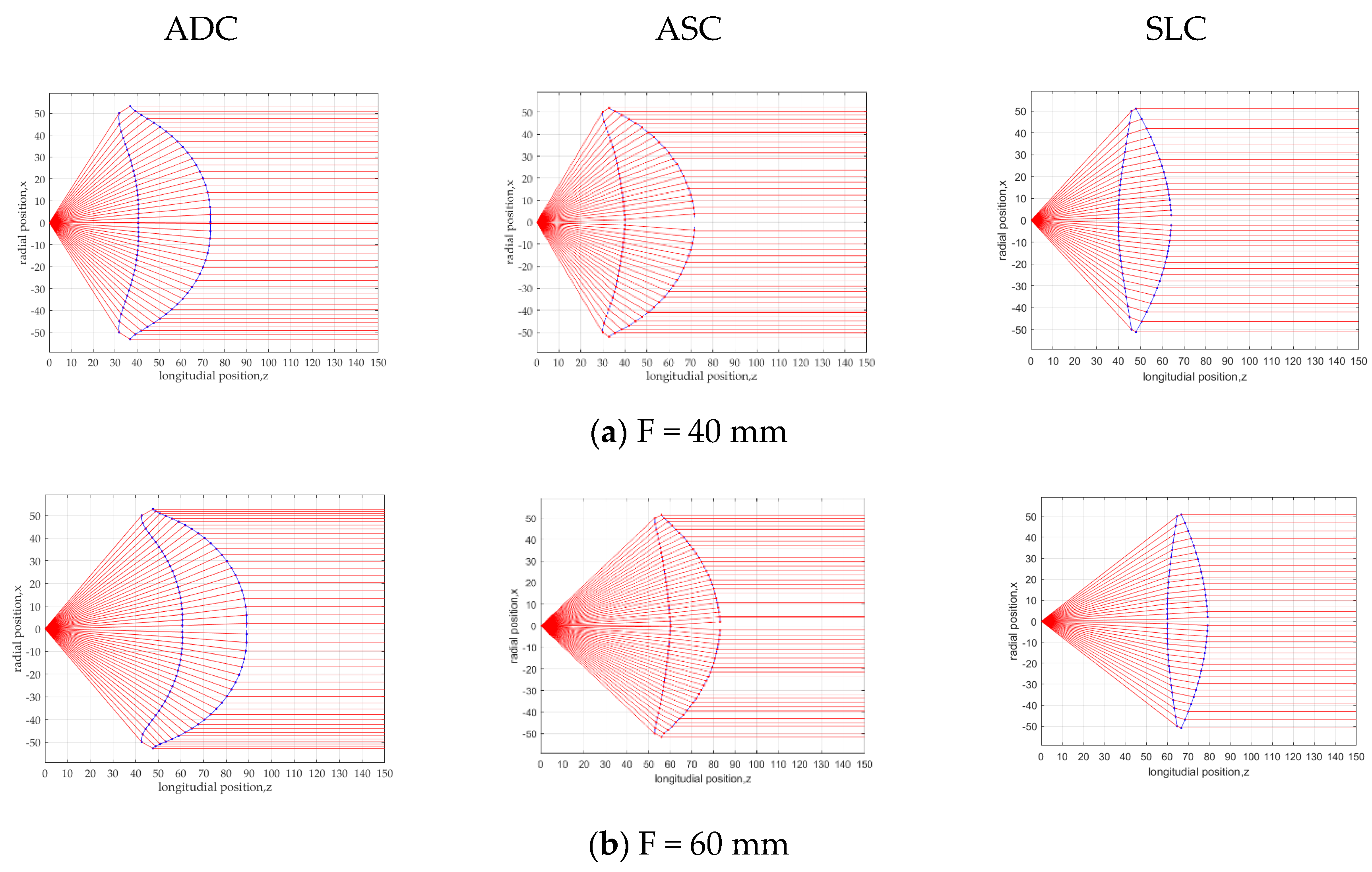
Figure 8.
Lens structure for ADC, ASC and SLC at a focal length of (a) F = 40 mm, (b) F = 60 mm.
Figure 8.
Lens structure for ADC, ASC and SLC at a focal length of (a) F = 40 mm, (b) F = 60 mm.
Figure 9.
Lens area ratio and thickness at focal length F = 40 mm, F = 60 mm and F = 100 mm.
Figure 9.
Lens area ratio and thickness at focal length F = 40 mm, F = 60 mm and F = 100 mm.
Figure 10.
Feed horn radiation pattern, Ep2(θ) = cos17θ, on x-z plane.
Figure 10.
Feed horn radiation pattern, Ep2(θ) = cos17θ, on x-z plane.
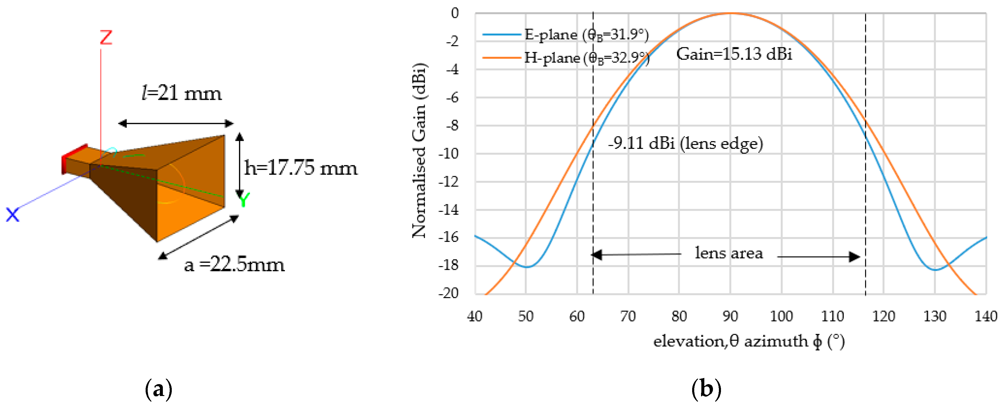
Figure 11.
(a) Dimension of feed horn antenna and (b) radiation pattern (y-z plane).
Figure 11.
(a) Dimension of feed horn antenna and (b) radiation pattern (y-z plane).
Figure 12.
Reflection coefficient of a 28.21 GHz feed horn antenna.
Figure 12.
Reflection coefficient of a 28.21 GHz feed horn antenna.
Figure 13.
Radiation pattern for ADC, ASC and SLC lens with theoretical gain value, GT = 29.34 dBi.
Figure 13.
Radiation pattern for ADC, ASC and SLC lens with theoretical gain value, GT = 29.34 dBi.
Figure 14.
Locus of feed position.
Figure 14.
Locus of feed position.
Figure 15.
(a) ADC structure; (b) Multi beam radiation patterns for ADC lens shape.
Figure 15.
(a) ADC structure; (b) Multi beam radiation patterns for ADC lens shape.
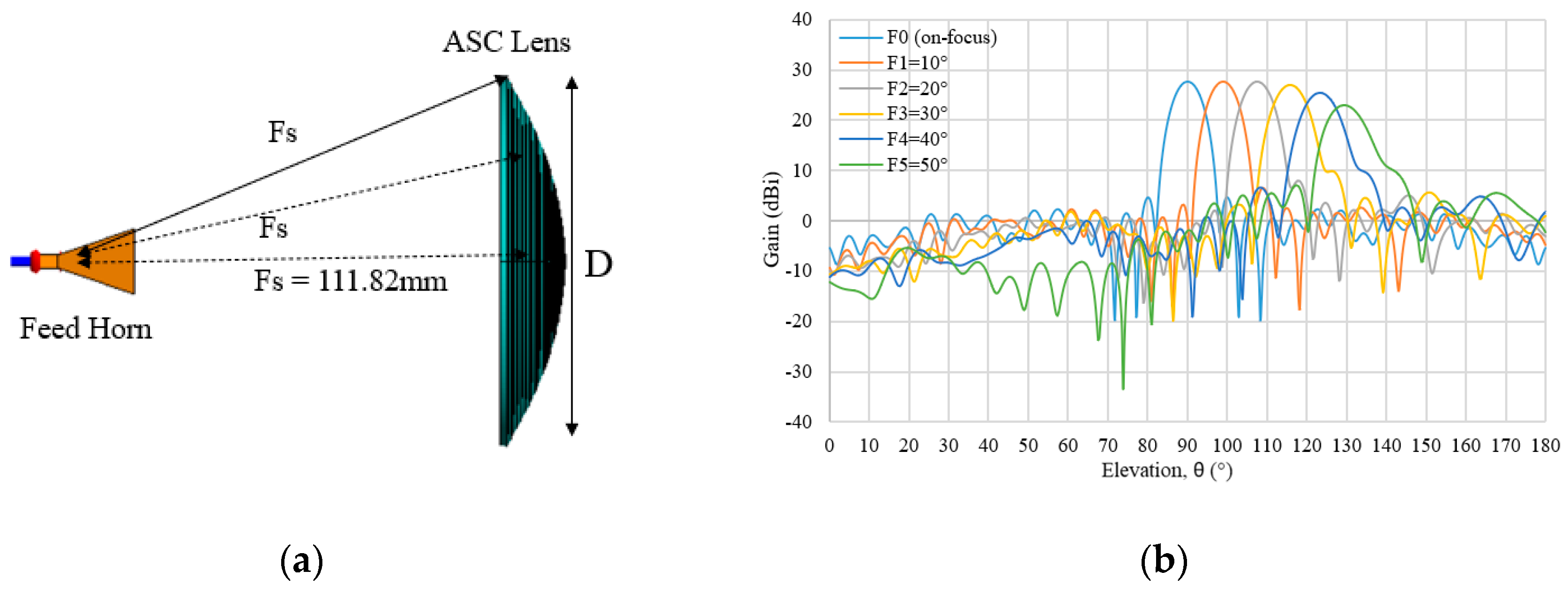
Figure 16.
(a) ASC structure; (b) Multi beam radiation pattern for ASC lens.
Figure 16.
(a) ASC structure; (b) Multi beam radiation pattern for ASC lens.
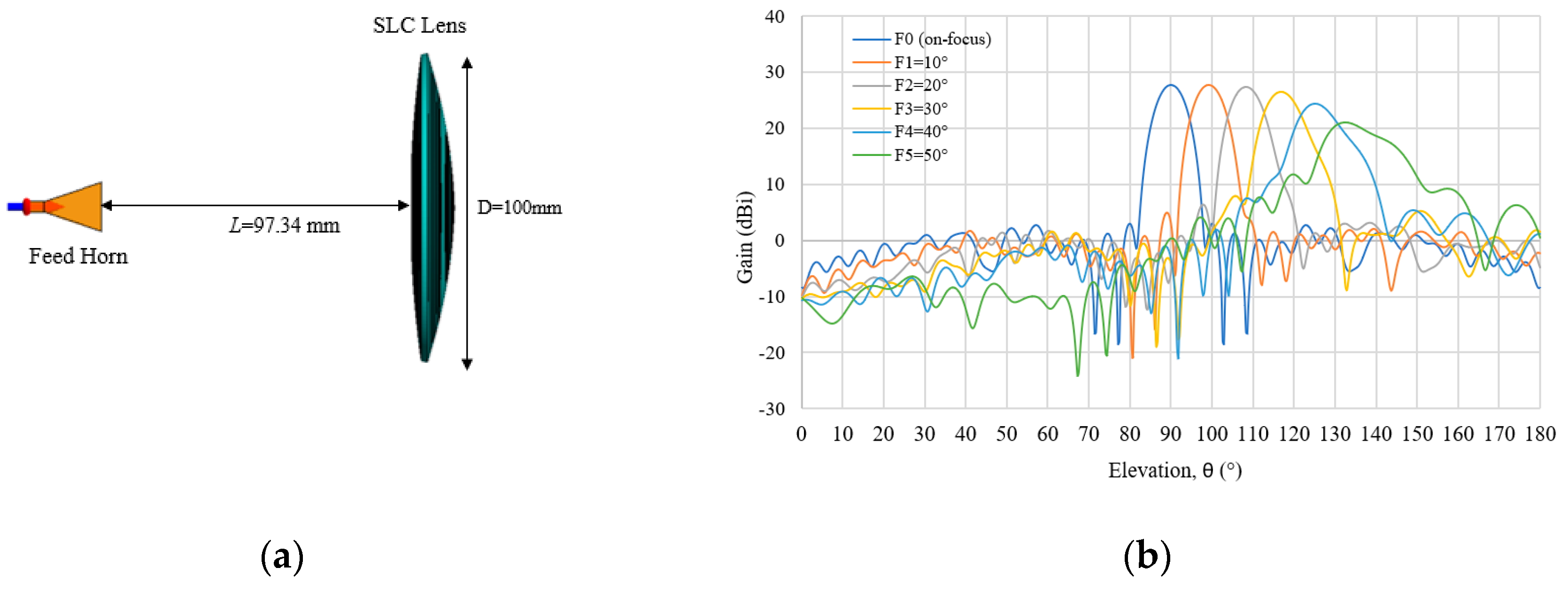
Figure 17.
(a) SLC structure; (b) Multi beam radiation pattern for SLC lens.
Figure 17.
(a) SLC structure; (b) Multi beam radiation pattern for SLC lens.
Figure 18.
SLC 2D radiation pattern at feed angle (a) θF = 0°, (b) θF = 20°, (c) θF = 40°.
Figure 18.
SLC 2D radiation pattern at feed angle (a) θF = 0°, (b) θF = 20°, (c) θF = 40°.
Figure 19.
Feed angle and beam direction of ADC, ASC and SLC.
Figure 19.
Feed angle and beam direction of ADC, ASC and SLC.
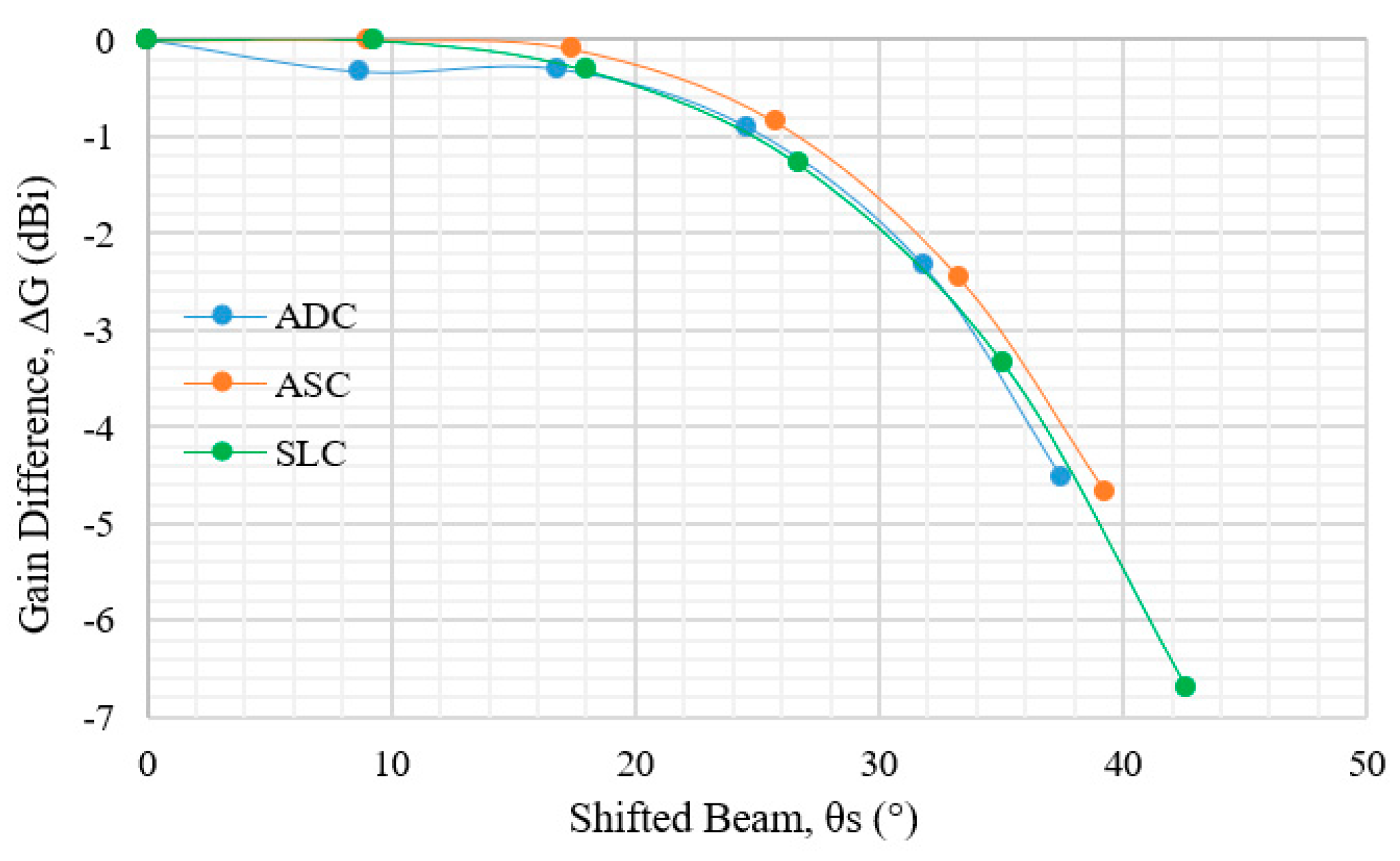
Figure 20.
Gain difference of each shifted beam for ADC, ASC and SLC.
Figure 20.
Gain difference of each shifted beam for ADC, ASC and SLC.
Table 1.
Dielectric lens antenna configuration.
Table 1.
Dielectric lens antenna configuration.
| Antenna Parameter | Dimension | Lens Shape | Dimension |
|---|
| General Specification | | Aperture Distribution (ADC) | |
| Operating Frequency, fo | 28.21 GHz | Focal Length, F | 106 mm |
| Max. angle, θm | 26.56° | Length from horn to lens edge, rm | 111.78 mm |
| Refractive index, n | 2 | Maximum radius of S2, Xm | 51.79 mm |
| Lens Diameter, D (10 λ) | 100 mm | Total electrical length, Lt | 266.98 mm |
| Initial condition of normal vector, θo | 10° | Lens Thickness, T | 17.00 mm |
| Initial condition at lens edge, do | 5 mm | Aperture distribution, E2d(x) | Equation (9) and Figure 3 |
| | | Abbe Sine Condition (ASC) | |
| Feed Horn {Ep2(θ)} | | Radius of circle, Fs | 111.82 mm |
| Equation (8) and Figure 10 | | Maximum radius of S2, Xm | 50.13 mm |
| | | Total electrical length, Lt | 252.84 mm |
| | | Lens Thickness, T | 14.80 mm |
| | | Straight Line Condition (SLC)—Proposed | |
| | | Distance to lens, L | 97.34 mm |
| | | Maximum radius of S2, Xm | 50.36 mm |
| | | Total electrical length, Lt | 253.89 mm |
| | | Lens Thickness, T | 13.83 mm |
Table 2.
Lens antenna parameter for F = 40 mm and F = 60 mm.
Table 2.
Lens antenna parameter for F = 40 mm and F = 60 mm.
| Antenna Parameter | ADC | ASC | SLC |
|---|
| | F = 40 | F = 60 | F = 40 | F = 60 | F = 40 | F = 60 |
|---|
| Max. angle, θm | 57.5 | 49.5 | 59.1 | 43.4 | 47.4 | 37.7 |
| m of Equation (8) | 5 | 10 | 5 | 10 | 5 | 10 |
| p of Equation (9) | 1 | 1 | 1 | 1 | 1 | 1 |
Table 3.
Simulation parameters of horn feed and dielectric lens antenna.
Table 3.
Simulation parameters of horn feed and dielectric lens antenna.
| Parameter | Specification |
|---|
| Computer | |
| Processor | Xeon 2.10 GHz |
| Random Access Memory | 512 GB |
| Electromagnetic Software | FEKO 2019.2 |
| Dielectric Lens Antenna | |
| Refractive index, n | 2 |
| Tan δ | 0.0004 |
| Mesh size | λ/8 |
| Number of meshes | 66,112 |
| Feed Horn | |
| Material | PEC |
| Mesh size | λ/12 |
| Number of meshes | 18,532 |
| Simulation Time (MoM) | 3H |
Table 4.
Lens antenna performance for ADC, ASC and SLC.
Table 4.
Lens antenna performance for ADC, ASC and SLC.
| Antenna Parameter | ADC | ASC | SLC |
|---|
| Gain of uniform aperture distribution, GT (dBi) | 29.34 | |
| Theoretical beam width, θBT | 6.25° |
| Simulated Beam Width, θBS | 6.55° | 6.40° | 6.54° |
| Simulated Gain, Gs (dBi) | 27.56 | 27.74 | 27.69 |
| Gain difference | −1.78 | −1.60 | −1.65 |
| Efficiency, η | 66.37% | 69.20% | 68.39% |
Table 5.
Feed Coordinate.
Table 5.
Feed Coordinate.
| Feed Angle (θF) | Feed Coordinate |
|---|
| | y | z |
|---|
| F1 = 10° | 4.49 | 16.84 |
| F2 = 20° | 17.03 | 30.20 |
| F3 = 30° | 35.06 | 37.50 |
| F4 = 40° | 55.05 | 37.72 |
| F5 = 50° | 73.45 | 31.65 |
Table 6.
Multi beam characteristics of ADC lens.
Table 6.
Multi beam characteristics of ADC lens.
| Feed Position | Feed Angle θF (°) | Shifted Beam θs (°) | HPBWθBS | Gain (dBi) | Gain Difference (dBi) |
|---|
| F0 | 0 | 0 | 6.54 | 27.55 | 0 |
| F1 | 10 | 8.7 | 6.66 | 27.22 | −0.33 |
| F2 | 20 | 16.8 | 7.00 | 27.25 | −0.30 |
| F3 | 30 | 24.6 | 7.57 | 26.65 | −0.90 |
| F4 | 40 | 31.8 | 8.00 | 25.23 | −2.32 |
| F5 | 50 | 37.5 | 8.03 | 23.03 | −4.52 |
Table 7.
Multi beam characteristics of ASC lens.
Table 7.
Multi beam characteristics of ASC lens.
| Feed Position | Feed Angle θF (°) | Shifted Beam θs (°) | HPBWθBS | Gain (dBi) | Gain Difference (dBi) |
|---|
| F0 | 0 | 0 | 6.40 | 27.77 | 0 |
| F1 | 10 | 9 | 6.50 | 27.77 | 0 |
| F2 | 20 | 17.4 | 6.83 | 27.68 | −0.09 |
| F3 | 30 | 25.8 | 7.33 | 26.92 | −0.85 |
| F4 | 40 | 33.3 | 7.89 | 25.31 | −2.46 |
| F5 | 50 | 39.3 | 8.55 | 23.09 | −4.68 |
Table 8.
Multi beam characteristics of SLC lens.
Table 8.
Multi beam characteristics of SLC lens.
| Feed Position | Feed Angle θF (°) | Shifted Beam θs (°) | HPBWθBS | Gain (dBi) | Gain Difference (dBi) |
|---|
| F0 | 0 | 0 | 6.54 | 27.69 | 0 |
| F1 | 10 | 9.3 | 6.63 | 27.69 | 0 |
| F2 | 20 | 18 | 7.00 | 27.38 | −0.31 |
| F3 | 30 | 26.7 | 7.83 | 26.41 | −1.28 |
| F4 | 40 | 35.1 | 9.13 | 24.35 | −3.34 |
| F5 | 50 | 42.6 | 14.33 | 21.00 | −6.69 |
Table 9.
Beam direction of ADC, ASC and SLC lenses.
Table 9.
Beam direction of ADC, ASC and SLC lenses.
| Feed Angle, θF | Beam Direction, θs |
|---|
| | ADC | ASC | SLC |
|---|
| 0 | 0 | 0 | 0 |
| 10 | 8.7 | 9 | 9.3 |
| 20 | 16.8 | 17.4 | 18 |
| 30 | 24.6 | 25.8 | 26.7 |
| 40 | 31.8 | 33.3 | 35.1 |
| 50 | 37.5 | 39.3 | 42.6 |

 ,
, 


