Tripping Avoidance Lower Extremity Exoskeleton Based on Virtual Potential Field for Elderly People


Abstract
:1. Introduction
2. Controller Design
3. Human–Exoskeleton Interactive Force and Virtual Force
3.1. Human–Exoskeleton Interactive Force
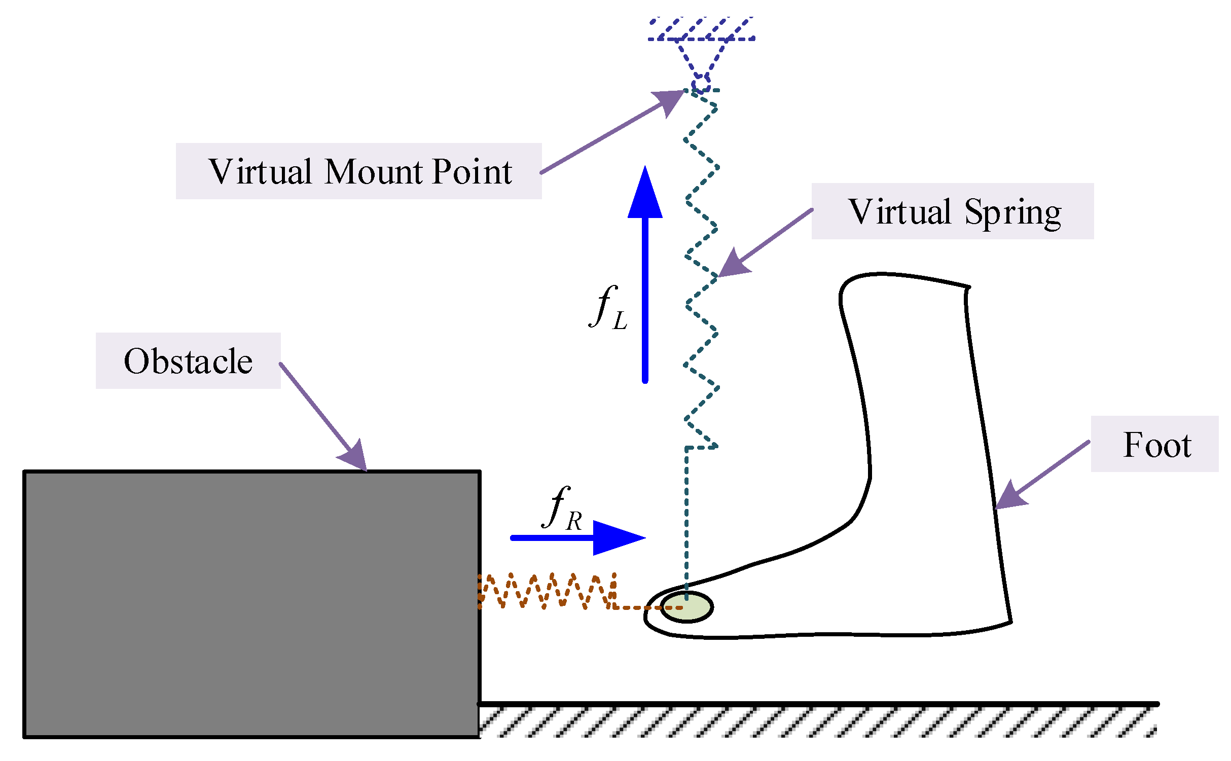
3.2. Virtual Force
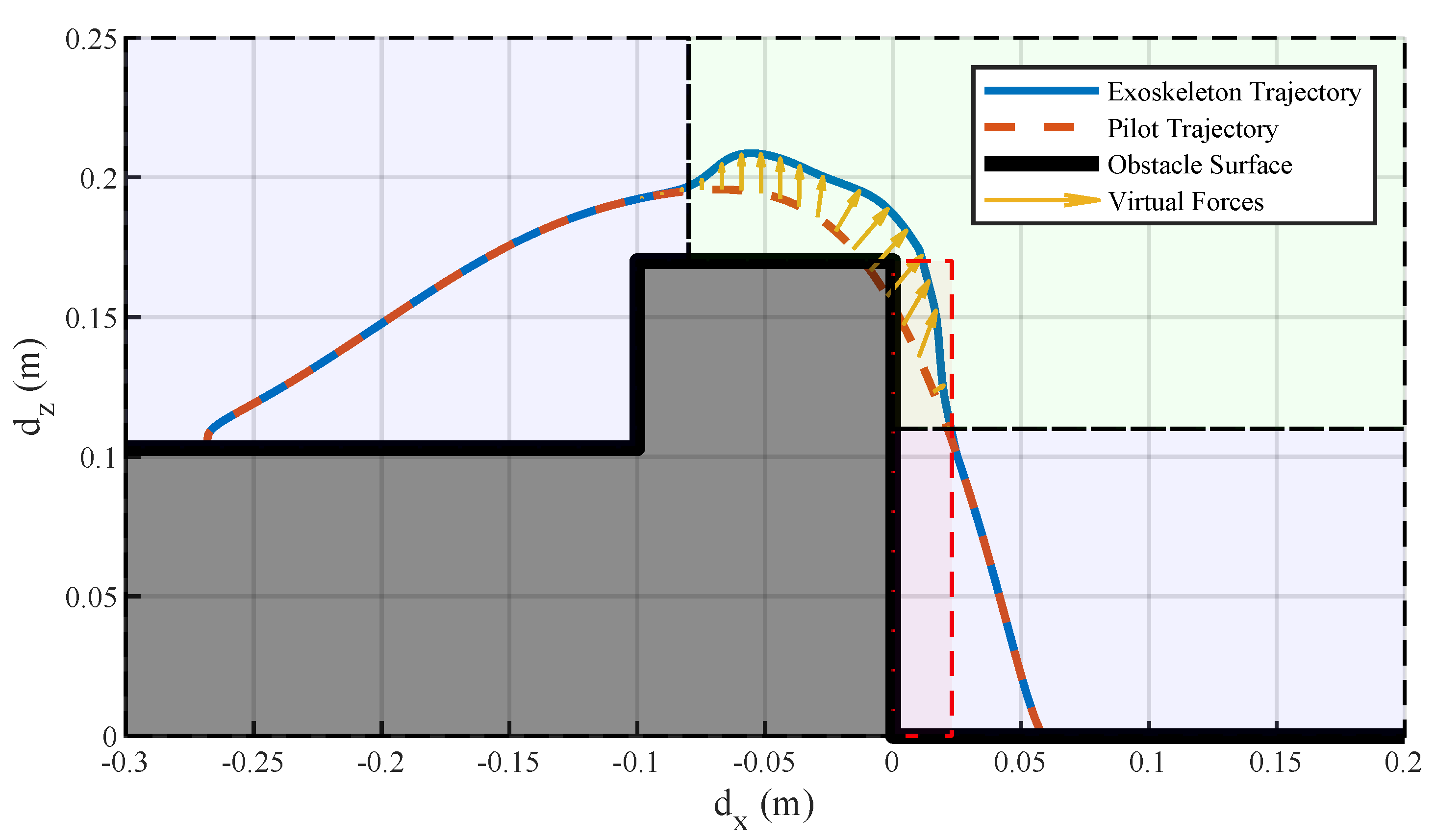
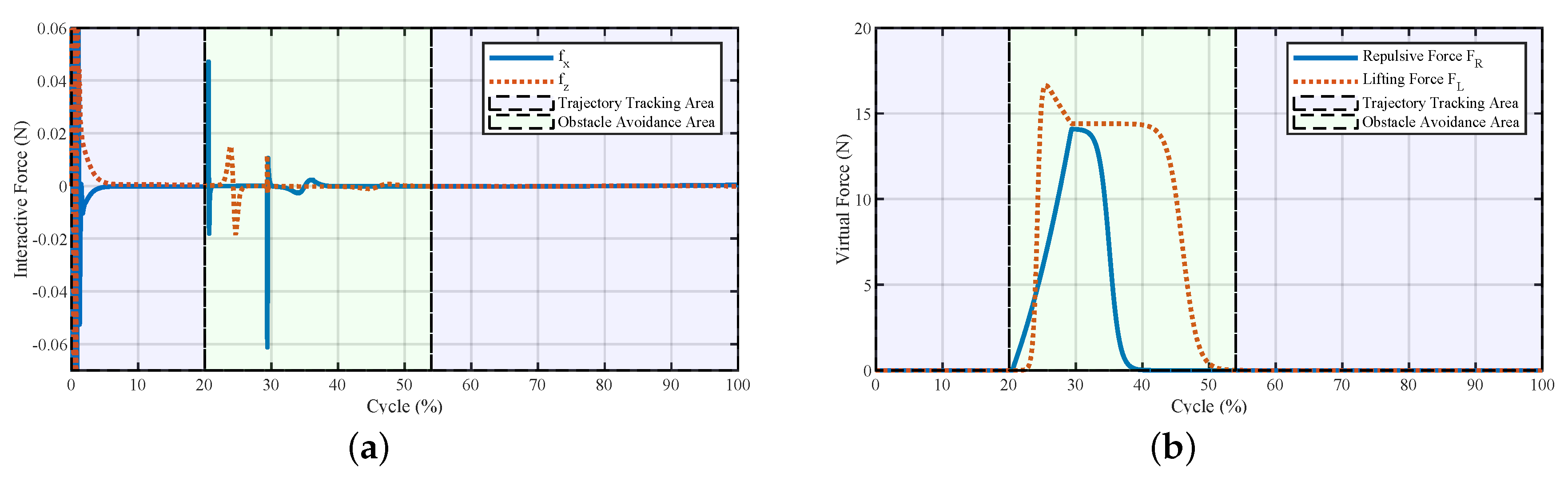
4. Simulation
5. Experiment
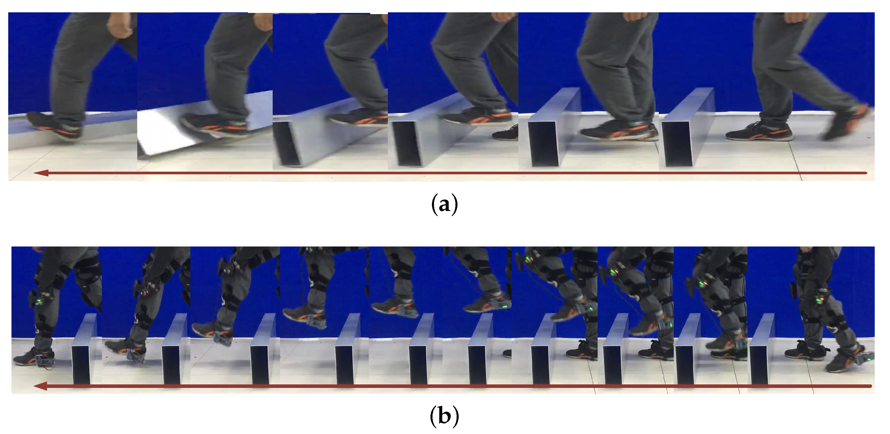
5.1. Step Over a Door Threshold
5.2. Step Over Obstacles
6. Discussion and Future Works
Author Contributions
Funding
Acknowledgments
Conflicts of Interest
References
- Seemongal-Dass, R.R.; James, T.E.; Atherley, C.E.; Chakravarty, M.; Sörman, A. Guidelines for prevention of falls in people aged over 65. BMJ 2001, 322, 554. [Google Scholar] [CrossRef] [PubMed]
- Wang, J.; Chen, Z.; Song, Y. Falls in aged people of the Chinese mainland: Epidemiology, risk factors and clinical strategies. Ageing Res. Rev. 2010, 9, S13–S17. [Google Scholar] [CrossRef]
- Pijnappels, M.; Bobbert, M.F.; Dieën, J.H.V. Push-off reactions in recovery after tripping discriminate young subjects, older non-fallers and older fallers. Gait Posture 2005, 21, 388–394. [Google Scholar] [CrossRef] [PubMed]
- Martelli, D.; Aprigliano, F.; Tropea, P.; Pasquini, G.; Micera, S.; Monaco, V. Stability against backward balance loss: Age-related modifications following slip-like perturbations of multiple amplitudes. Gait Posture 2017, 53, 207–214. [Google Scholar] [CrossRef] [PubMed]
- Blake, A.J.; Morgan, K.; Bendall, M.J.; Dallosso, H.; Ebrahim, S.B.J.; Arie, T.H.D.; Fentem, P.H.; Bassey, E.J. Falls by elderly people at home: Prevalence and associated factors. Age Ageing 1988, 17, 65–372. [Google Scholar] [CrossRef]
- Tinetti, M.E.; Speechley, M.; Ginter, S.F. Risk Factors for falls among elderly persons living in the community. N. Engl. J. Med. 1988, 319, 1701–1707. [Google Scholar] [CrossRef]
- Srygley, J.M.; Herman, T.; Giladi, N.; Hausdorff, J.M. Self-report of missteps in older adults: A valid proxy of fall risk? Arch. Phys. Med. Rehabil. 2009, 90, 786–792. [Google Scholar] [CrossRef] [Green Version]
- Senden, R.; Savelberg, H.H.C.M.; Adam, J.; Grimm, B.; Heyligers, I.C.; Meijer, K. The influence of age, muscle strength and speed of information processing on recovery responses to external perturbations in gait. Gait Posture 2014, 39, 513–517. [Google Scholar] [CrossRef]
- Shirota, C.; Simon, A.M.; Kuiken, T.A. Trip recovery strategies following perturbations of variable duration. J. Biomech. 2014, 47, 2679–2684. [Google Scholar] [CrossRef] [PubMed] [Green Version]
- Cordero, A.F.; Koopman, H.F.J.M.; der Helm, F.C.T.V. Multiple-step strategies to recover from stumbling perturbations. Gait Posture 2003, 18, 47–59. [Google Scholar] [CrossRef]
- Eng, J.J.; Winter, D.A.; Patla, A.E. Strategies for recovery from a trip in early and late swing during human walking. Exp. Brain Res. 1994, 102, 339–349. [Google Scholar] [CrossRef] [PubMed]
- Roos, P.E.; McGuigan, M.P.; Trewartha, G. The role of strategy selection, limb force capacity and limb positioning in successful trip recovery. Clin. Biomech. 2010, 25, 873–878. [Google Scholar] [CrossRef] [PubMed] [Green Version]
- Schillings, A.M.; Wezel, B.M.H.V.; Mulder, T.; Duysens, J. Muscular responses and movement strategies during stumbling over obstacles. J. Neurophysiol. 2000, 83, 2093–2102. [Google Scholar] [CrossRef] [PubMed] [Green Version]
- Den Bogert, A.J.V.; Pavol, M.J.; Grabiner, M.D. Response time is more important than walking speed for the ability of older adults to avoid a fall after a trip. J. Biomech. 2002, 35, 199–205. [Google Scholar] [CrossRef] [Green Version]
- Bair, W.N.; Prettyman, M.G.; Beamer, B.A.; Rogers, M.W. Kinematic and behavioral analyses of protective stepping strategies and risk for falls among community living older adults. Clin. Biomech. 2016, 36, 74–82. [Google Scholar] [CrossRef] [Green Version]
- Crenshaw, J.R.; Grabiner, M.D. The influence of age on the thresholds of compensatory stepping and dynamic stability maintenance. Gait Posture 2014, 40, 363–368. [Google Scholar] [CrossRef]
- Jung, M.M.; Ludden, G.D.S. Potential of exoskeleton technology to assist older adults with daily living. In Proceedings of the Extended abstracts of the 2018 CHI Conference on Human Factors in Computing Systems, Montreal, QC, Canada, 21–26 April 2018; pp. 2–7. [Google Scholar]
- Zoss, A.B.; Kazerooni, H.; Chu, A. Biomechanical design of the Berkeley lower extremity exoskeleton (BLEEX). IEEE/ASME Trans. Mechatron. 2006, 11, 128–138. [Google Scholar] [CrossRef]
- Karlin, S. Raiding Iron Man’s closet: A real-life Iron Man suit is almost ready to wear. IEEE Spectr. 2011, 48, 25. [Google Scholar] [CrossRef] [Green Version]
- Sankai, Y. HAL: Hybrid assistive limb based on cybernics. In Springer Tracts in Advanced Robotics; Springer: Berlin/Heidelberg, Germany, 2010; Volume 66, pp. 25–34. [Google Scholar]
- Fontana, M.; Vertechy, R.; Marcheschi, S.; Salsedo, F.; Bergamasco, M. The body extender: A full-body exoskeleton for the transport and handling of heavy loads. IEEE Robot. Autom. Mag. 2014, 21, 34–44. [Google Scholar] [CrossRef]
- Chu, G.; Hong, J.; Jeong, D.; Kim, D.; Kim, S.; Jeong, S.; Choo, J. The experiments of wearable robot for carrying heavy-weight objects of shipbuilding works. In Proceedings of the IEEE International Conference on Automation Science and Engineering, Taipei, Taiwan, 18–22 August 2014; pp. 978–983. [Google Scholar]
- Zhu, Y.; Zhang, G.; Zhang, C.; Liu, G.; Zhao, J. Biomechanical modeling and load-carrying simulation of lower limb exoskeleton. Biomed. Mater. Eng. 2015, 26, S729–S738. [Google Scholar] [CrossRef] [Green Version]
- Choo, J.; Park, J.H. Increasing payload capacity of wearable robots using linear actuators. IEEE/ASME Trans. Mechatron. 2017, 13, 1. [Google Scholar] [CrossRef]
- Kong, K.; Jeon, D. Design and control of an exoskeleton for the elderly and patients. IEEE/ASME Trans. Mechatron. 2006, 11, 428–432. [Google Scholar] [CrossRef]
- Bao, T.; Carender, W.J.; Kinnaird, C.; Barone, V.J.; Peethambaran, G.; Whitney, S.L.; Kabeto, M.; Seidler, R.D.; Sienko, K.H. Effects of long-term balance training with vibrotactile sensory augmentation among community-dwelling healthy older adults: A randomized preliminary study. J. Neuroeng. Rehabil. 2018, 15, 1–13. [Google Scholar] [CrossRef] [PubMed] [Green Version]
- Takahashi, K.Z.; Lewek, M.D.; Sawicki, G.S. A neuromechanics-based powered ankle exoskeleton to assist walking post-stroke: A feasibility study. J. Neuroeng. Rehabil. 2015, 12, 23. [Google Scholar] [CrossRef] [PubMed] [Green Version]
- Esquenazi, A.; Talaty, M.; Packel, A.; Saulino, M. The Rewalk powered exoskeleton to restore ambulatory function to individuals with thoracic-level motor-complete spinal cord injury. Am. J. Phys. Med. Rehabil. 2012, 91, 911–921. [Google Scholar] [CrossRef] [PubMed] [Green Version]
- Strausser, K.; Kazerooni, H. The development and testing of a human machine interface for a mobile medical exoskeleton. In Proceedings of the IEEE International Conference on Intelligent Robots and Systems, San Francisco, CA, USA, 25–30 September 2011; pp. 4911–4916. [Google Scholar]
- Woods, C.; Callagher, L.; Jaffray, T. Walk tall: The story of Rex Bionics. J. Manag. Organ. 2018, 1–14. [Google Scholar] [CrossRef]
- Kazerooni, H. The Berkeley lower extremity exoskeleton. J. Dyn. Syst. Meas. Control 2006, 21, 291–301. [Google Scholar]
- Yamamoto, K.; Ishii, M.; Noborisaka, H.; Hyodo, K. Stand alone wearable power assisting suit— Sensing and control systems. In Proceedings of the International Workshop on Robot and Human Interactive Communication, Okayama, Japan, 22 September 2004; pp. 661–666. [Google Scholar]
- Lucchesi, N.; Marcheschi, S.; Borelli, L.; Salsedo, F.; Fontana, M.; Bergamasco, M. An approach to the design of fully actuated body extenders for material handling. In Proceedings of the IEEE International Workshop on Robot and Human Interactive Communication, Viareggio, Italy, 13–15 September 2010; pp. 482–487. [Google Scholar]
- Hayashi, T.; Kawamoto, H.; Sankai, Y. Control method of robot suit HAL working as operator’s muscle using biological and dynamical information. In Proceedings of the IEEE/RSJ International Conference on Intelligent Robots and Systems, Edmonton, AB, Canada, 2–6 August 2005; Volume 2, pp. 3455–3460. [Google Scholar]
- Kwa, H.K.; Noorden, J.H.; Missel, M.; Craig, T.; Pratt, J.E.; Neuhaus, P.D. Development of the IHMC mobility assist exoskeleton. In Proceedings of the IEEE International Conference on Robotics and Automation, Kobe, Japan, 12–17 May 2009; pp. 2556–2562. [Google Scholar]
- Tsukahara, A.; Kawanishi, R.; Hasegawa, Y.; Sankai, Y. Sit-to-stand and stand-to-sit transfer support for complete paraplegic patients with robot suit HAL. Adv. Robot. 2010, 24, 1615–1638. [Google Scholar] [CrossRef] [Green Version]
- Talaty, M.; Esquenazi, A.; Briceno, J.E. Differentiating ability in users of the ReWalkTM powered exoskeleton: An analysis of walking kinematics. In Proceedings of the IEEE International Conference on Rehabilitation Robotics, Seattle, WA, USA, 24–26 June 2013; pp. 1–5. [Google Scholar]
- Hyon, S.H.; Morimoto, J.; Matsubara, T.; Noda, T.; Kawato, M. XoR: Hybrid drive exoskeleton robot that can balance. In Proceedings of the IEEE International Conference on Intelligent Robots and Systems, San Francisco, CA, USA, 25–30 September 2011; pp. 3975–3981. [Google Scholar]
- Chuy, O.; Hirata, Y.; Kosuge, K. Control of walking support system based on variable center of rotation. In Proceedings of the IEEE/RSJ International Conference on Intelligent Robots and Systems, Sendai, Japan, 28 September–2 October 2004; Volume 3, pp. 2289–2294. [Google Scholar]
- Ikehara, T.; Nagamura, K.; Ushida, T.; Tanaka, E.; Saegusa, S.; Kojima, S.; Yuge, L. Development of closed-fitting-type walking assistance device for legs and evaluation of muscle activity. In Proceedings of the IEEE International Conference on Rehabilitation Robotics, Zurich, Switzerland, 29 June–1 July 2011; pp. 1–7. [Google Scholar]
- Yang, Z.; Zhu, Y.; Yang, X.; Zhang, Y. Impedance control of exoskeleton suit based on RBF adaptive network. In Proceedings of the IEEE Conference on Intelligent Human-Machine Systems and Cybernetics, Hangzhou, China, 26–27 August 2009; pp. 182–187. [Google Scholar]
- Byju, A.G.; Nussbaum, M.A.; Madigan, M.L. Alternative measures of toe trajectory more accurately predict the probability of tripping than minimum toe clearance. J. Biomech. 2016, 49, 4016–4021. [Google Scholar] [CrossRef] [Green Version]
- Feng, G. A compensating scheme for robot tracking based on neural networks. Robot. Auton. Syst. 1995, 15, 199–206. [Google Scholar] [CrossRef]
- He, W.; Chen, Y.; Yin, Z. Adaptive neural network control of an uncertain robot with full-state constraints. IEEE Trans. Cybern. 2016, 46, 620–629. [Google Scholar] [CrossRef] [PubMed]
- Park, H.; Lee, J.M. Adaptive impedance control of a haptic interface. Mechatronics 2004, 14, 237–253. [Google Scholar] [CrossRef]
- Wang, H.; Low, K.H.; Wang, M.Y. Environment estimation for enhanced impedance control. In Proceedings of the IEEE International Conference on Robotics and Automation, Nagoya, Japan, 21–27 May 1995; pp. 1854–1859. [Google Scholar]
- Love, L.; Book, W. Reference trajectory generation for force tracking impedance control by using neural network-based environment estimation. In Proceedings of the IEEE Conference on Robotics, Automation and Mechatronics, Bangkok, Thailand, 1–3 June 2006; pp. 1–6. [Google Scholar]
- Kincaid, D.; Cheney, W. Numerical Analysis–Mathematics of Scientific Computing. Math. Comput. 1992, 59, 297. [Google Scholar]
- Hamel, K.A.; Okita, N.; Higginson, J.S.; Cavanagh, P.R. Foot clearance during stair descent: Effects of age and illumination. Gait Posture 2005, 21, 135–140. [Google Scholar] [CrossRef]
- Lai, D.T.H.; Taylor, S.B.; Begg, R.K. Prediction of foot clearance parameters as a precursor to forecasting the risk of tripping and falling. Hum. Mov. Sci. 2012, 31, 271–283. [Google Scholar] [CrossRef]
- Loverro, K.L.; Mueske, N.M.; Hamel, K.A. Location of minimum foot clearance on the shoe and with respect to the obstacle changes with locomotor task. J. Biomech. 2013, 46, 1842–1850. [Google Scholar] [CrossRef] [Green Version]
- Kesler, R.M.; Horn, G.P.; Rosengren, K.S.; Hsiao-Wecksler, E.T. Analysis of foot clearance in firefighters during ascent and descent of stairs. Appl. Ergon. 2016, 52, 18–23. [Google Scholar] [CrossRef]
- Khatib, O. Real-time obstacle avoidance for manipulators and mobile robots. Int. J. Robot. Res. 1986, 5, 874–881. [Google Scholar] [CrossRef]
- Winter, D.A. Human balance and posture control during standing and walking. Gait Posture 1995, 3, 193–214. [Google Scholar] [CrossRef]
- Buurke, T.J.W.; Lamoth, C.J.C.; Vervoort, D.; van der Woude, L.H.V.; den Otter, R. Adaptive control of dynamic balance in human gait on a split-belt treadmill. J. Exp. Biol. 2018, 221. [Google Scholar] [CrossRef] [Green Version]


Publisher’s Note: MDPI stays neutral with regard to jurisdictional claims in published maps and institutional affiliations. |
© 2020 by the authors. Licensee MDPI, Basel, Switzerland. This article is an open access article distributed under the terms and conditions of the Creative Commons Attribution (CC BY) license (http://creativecommons.org/licenses/by/4.0/).
Share and Cite
Zhang, Z.; Li, C.; Zheng, T.; Li, H.; Zhao, S.; Zhao, J.; Zhu, Y. Tripping Avoidance Lower Extremity Exoskeleton Based on Virtual Potential Field for Elderly People. Sensors 2020, 20, 5844. https://doi.org/10.3390/s20205844
Zhang Z, Li C, Zheng T, Li H, Zhao S, Zhao J, Zhu Y. Tripping Avoidance Lower Extremity Exoskeleton Based on Virtual Potential Field for Elderly People. Sensors. 2020; 20(20):5844. https://doi.org/10.3390/s20205844
Chicago/Turabian StyleZhang, Zongwei, Changle Li, Tianjiao Zheng, Hongwu Li, Sikai Zhao, Jie Zhao, and Yanhe Zhu. 2020. "Tripping Avoidance Lower Extremity Exoskeleton Based on Virtual Potential Field for Elderly People" Sensors 20, no. 20: 5844. https://doi.org/10.3390/s20205844
APA StyleZhang, Z., Li, C., Zheng, T., Li, H., Zhao, S., Zhao, J., & Zhu, Y. (2020). Tripping Avoidance Lower Extremity Exoskeleton Based on Virtual Potential Field for Elderly People. Sensors, 20(20), 5844. https://doi.org/10.3390/s20205844