Design, Fabrication, and Performance Evaluation of Portable and Large-Area Blackbody System

 , , , ,
Abstract
:1. Introduction
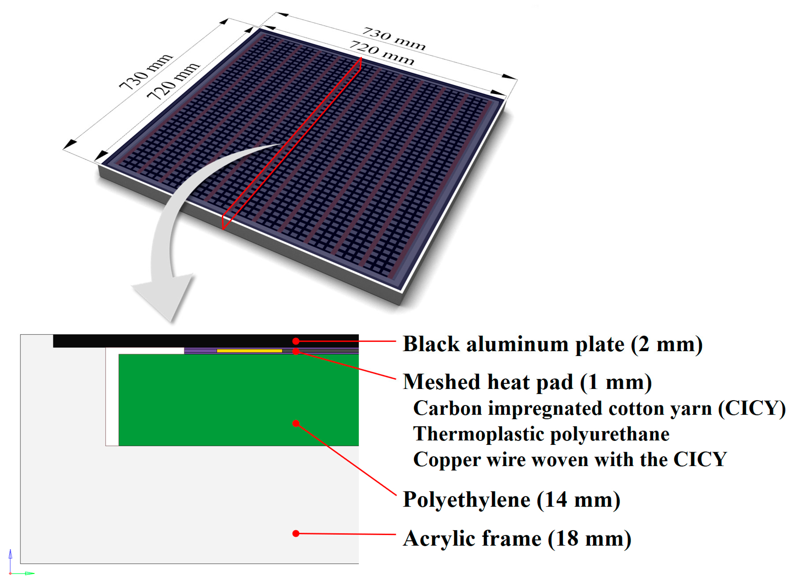
2. Design
3. Numerical Simulations
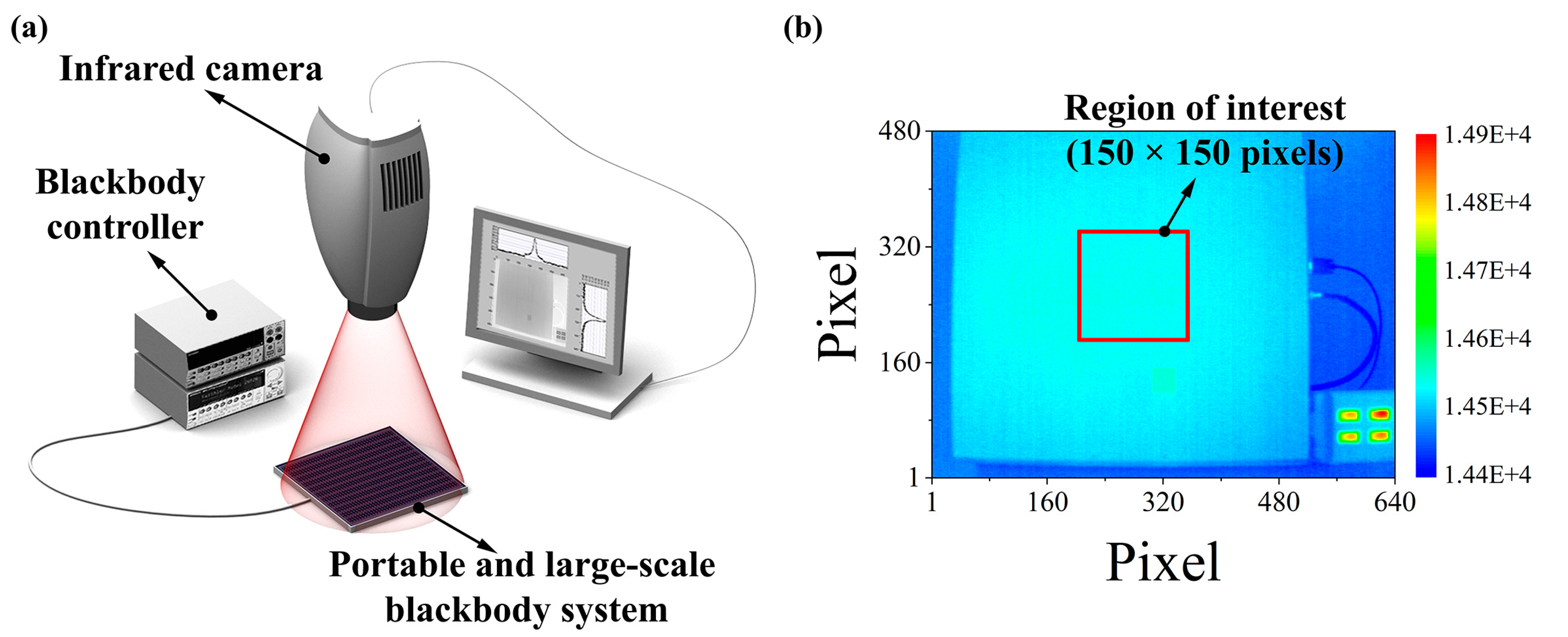
4. Experimental Performance Evaluation of Portable and Large-Area Blackbody System
5. Results and Discussion
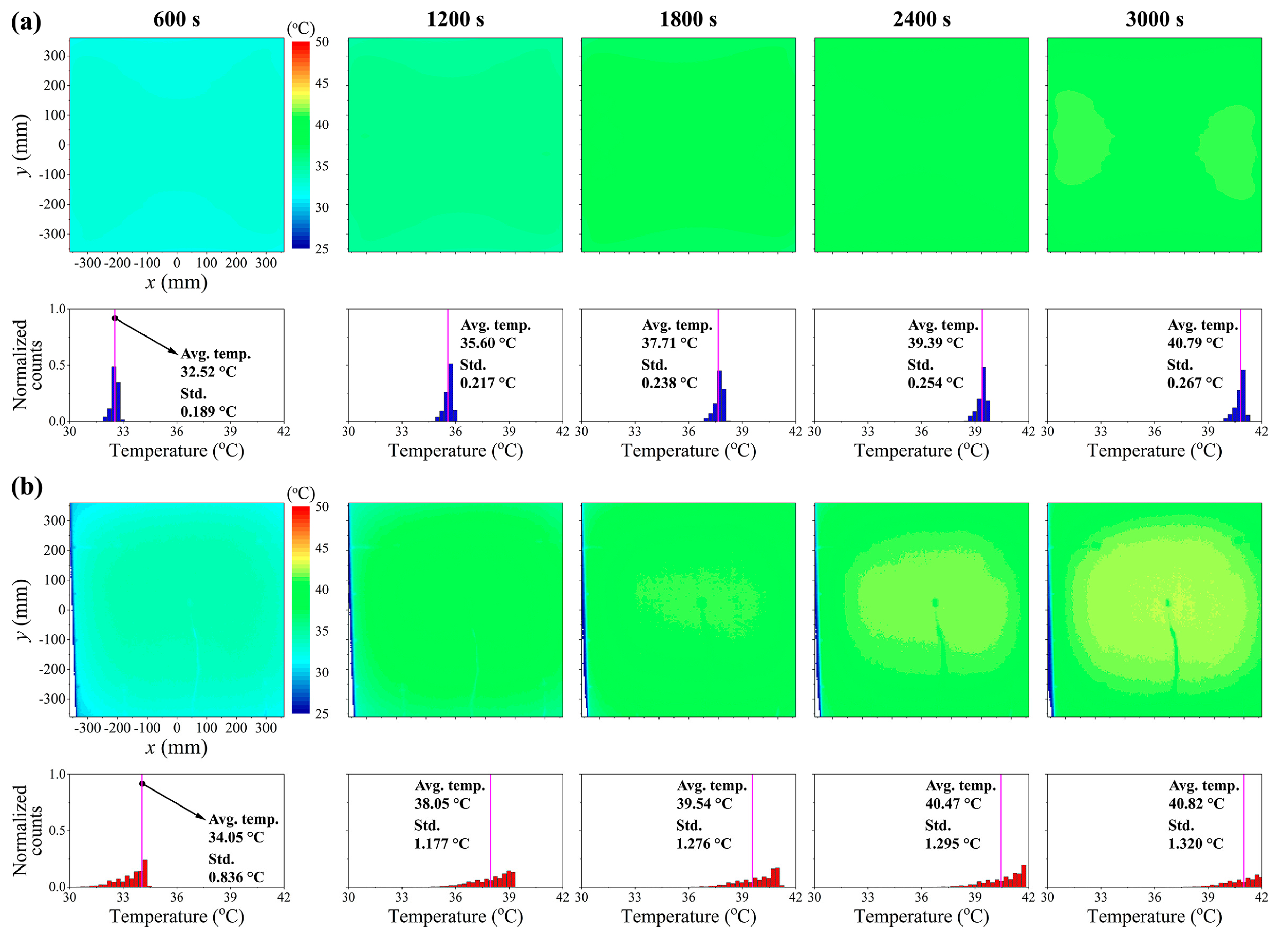
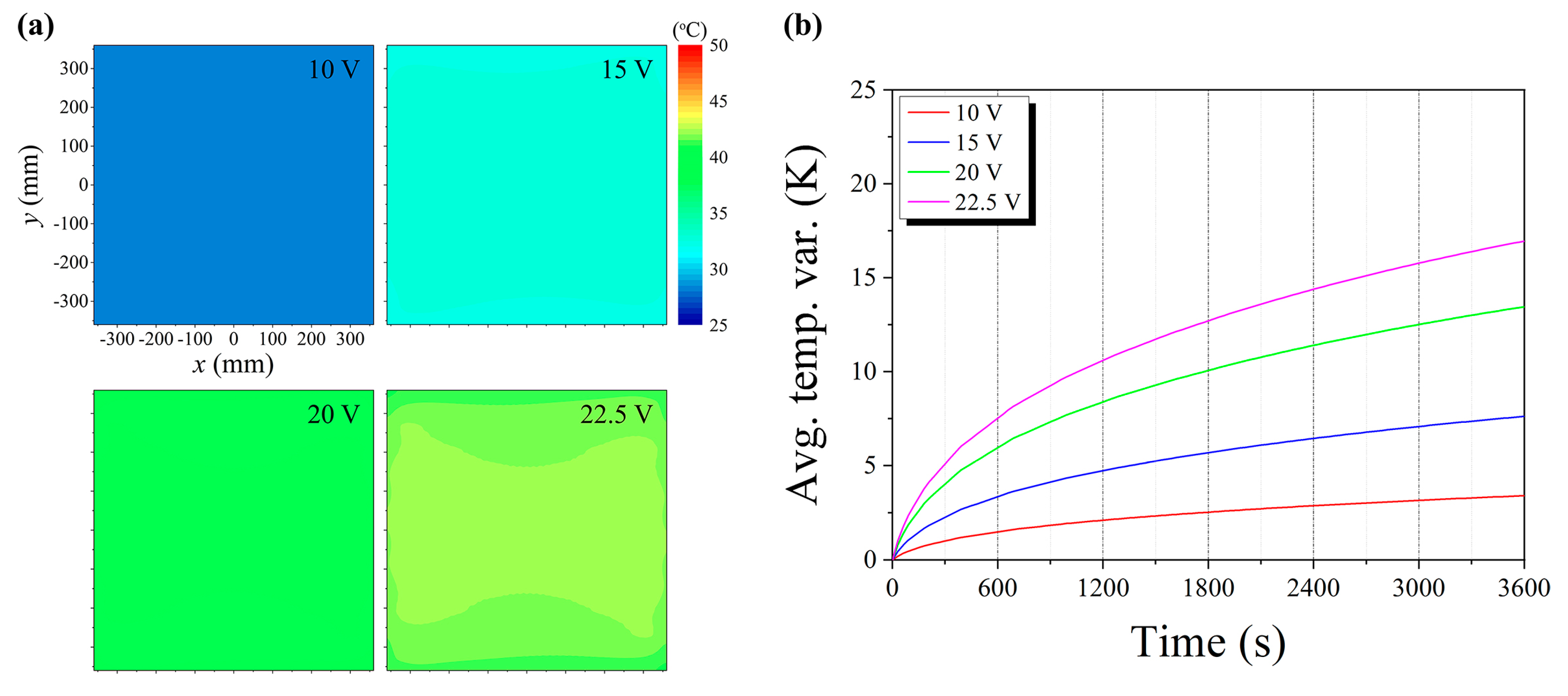
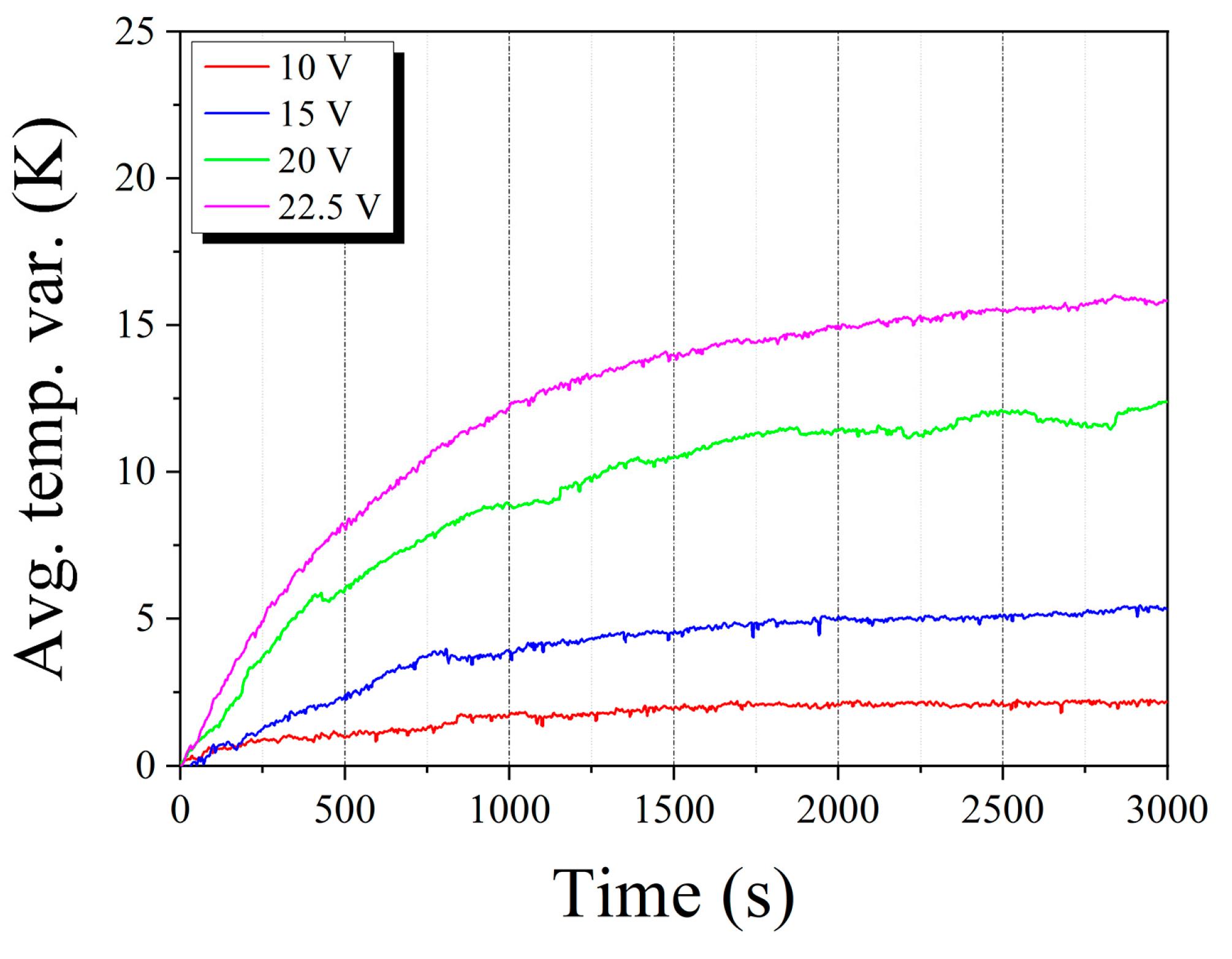
5.1. Transient Thermal Responses of Portable and Large-Area Blackbody System
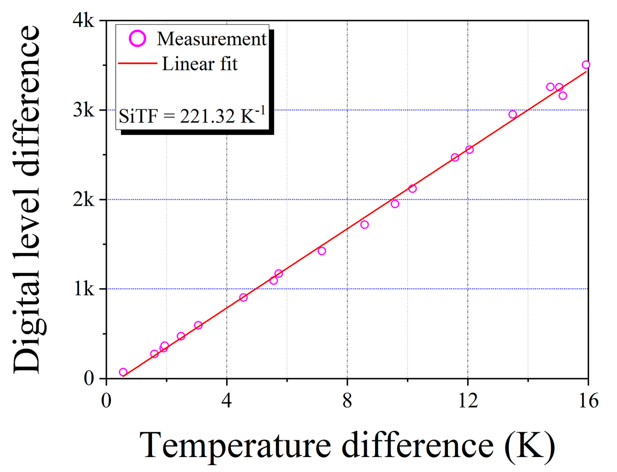
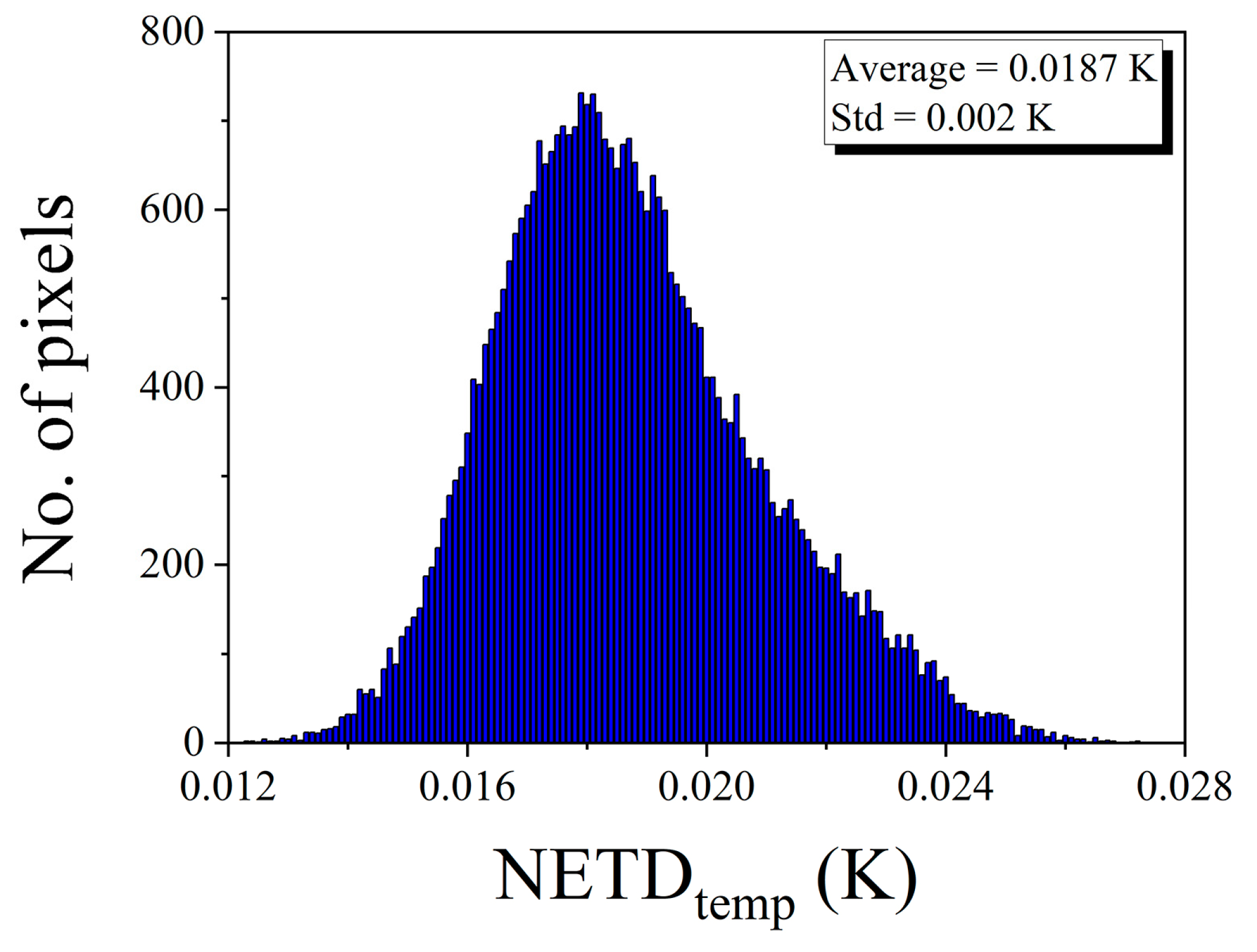
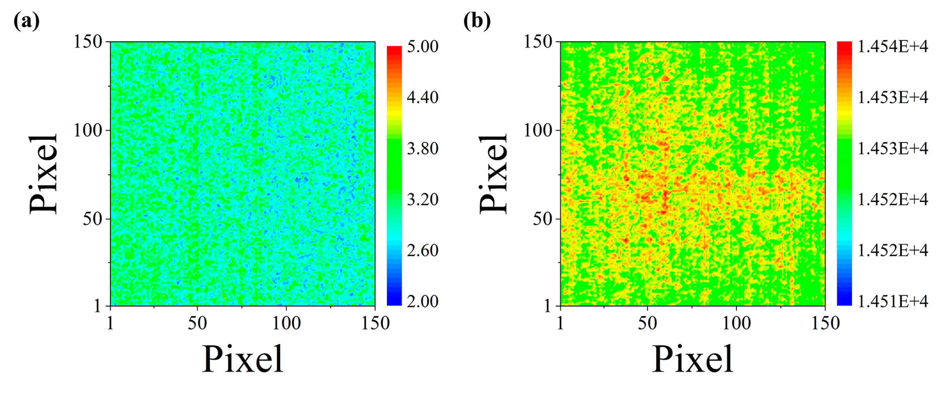
5.2. Signal Transfer Function (SiTF), Noise-Equivalent Temperature Difference (NETD), and Emissivity of Portable and Large-Area Blackbody System
6. Conclusions
Author Contributions
Funding
Conflicts of Interest
References
- Zhang, C.; Kovacs, J.M. The application of small unmanned aerial systems for precision agriculture: A review. Precis. Agric. 2012, 13, 693–712. [Google Scholar] [CrossRef]
- Ham, Y.; Han, K.K.; Lin, J.J.; Golparvar-Fard, M. Visual monitoring of civil infrastructure systems via camera-equipped Unmanned Aerial Vehicles (UAVs): A review of related works. Vis. Eng. 2016, 4, 1–8. [Google Scholar] [CrossRef] [Green Version]
- Nex, F.; Remondino, F. UAV for 3D mapping applications: A review. Appl. Geomat. 2014, 6, 1–15. [Google Scholar] [CrossRef]
- Abd-Elrahman, A.; Pearlstine, L.; Percival, F. Development of pattern recognition algorithm for automatic bird detection from unmanned aerial vehicle imagery. Surv. Land Inf. Sci. 2005, 65, 37–45. [Google Scholar]
- Hong, S.-J.; Han, Y.; Kim, S.-Y.; Lee, A.-Y.; Kim, G. Application of Deep-Learning Methods to Bird Detection Using Unmanned Aerial Vehicle Imagery. Sensors 2019, 19, 1651. [Google Scholar] [CrossRef] [Green Version]
- Ballester, C.; Jiménez-Bello, M.A.; Castel, J.R.; Intrigliolo, D.S. Usefulness of thermography for plant water stress detection in citrus and persimmon trees. Agric. For. Meteorol. 2013, 168, 120–129. [Google Scholar] [CrossRef]
- Chen, C. Determining the leaf emissivity of three crops by infrared thermometry. Sensors 2015, 15, 11387–11401. [Google Scholar] [CrossRef] [Green Version]
- Ihuoma, S.O.; Madramootoo, C.A. Recent advances in crop water stress detection. Comput. Electron. Agric. 2017, 141, 267–275. [Google Scholar] [CrossRef]
- Lee, A.-Y.; Kim, S.-Y.; Hong, S.-J.; Han, Y.; Choi, Y.; Kim, M.; Yun, S.K.; Kim, G. Phenotypic Analysis of Fruit Crops Water Stress Using Infrared Thermal Imaging. J. Biosyst. Eng. 2019, 44, 87–94. [Google Scholar] [CrossRef]
- Berni, J.A.J.; Zarco-Tejada, P.J.; Suarez, L.; Fereres, E. Thermal and narrowband multispectral remote sensing for vegetation monitoring from an unmanned aerial vehicle. IEEE Trans. Geosci. Remote Sens. 2009, 47, 722–738. [Google Scholar] [CrossRef] [Green Version]
- Bellvert, J.; Zarco-Tejada, P.J.; Girona, J.; Fereres, E. Mapping crop water stress index in a ‘Pinot-noir’ vineyard: Comparing ground measurements with thermal remote sensing imagery from an unmanned aerial vehicle. Precis. Agric. 2014, 15, 361–376. [Google Scholar] [CrossRef]
- Jha, S.N.; Narsaiah, K.; Basediya, A.L.; Sharma, R.; Jaiswal, P.; Kumar, R.; Bhardwaj, R. Measurement techniques and application of electrical properties for nondestructive quality evaluation of foods–A review. J. Food Sci. Technol. 2011, 48, 387–411. [Google Scholar] [CrossRef] [PubMed] [Green Version]
- Kim, G.; Lim, G.-H.; Park, J.; Kim, D.-Y.; Cho, B.-K. Application of infrared lock-in thermography for the quantitative evaluation of bruises on pears. Infrared Phys. Technol. 2014, 63, 133–139. [Google Scholar] [CrossRef]
- Baranowski, P.; Mazurek, W.; Walczak, R.T. The use of thermography for presowing evaluation of seed germination capacity. Acta Hortic. 2003, 604, 459–465. [Google Scholar] [CrossRef]
- Santesteban, L.G.; Di Gennaro, S.F.; Herrero-Langreo, A.; Miranda, C.; Royo, J.B.; Matese, A. High-resolution UAV-based thermal imaging to estimate the instantaneous and seasonal variability of plant water status within a vineyard. Agric. Water Manag. 2017, 183, 49–59. [Google Scholar] [CrossRef]
- Ribeiro-Gomes, K.; Hernández-López, D.; Ortega, J.; Ballesteros, R.; Poblete, T.; Moreno, M. Uncooled thermal camera calibration and optimization of the photogrammetry process for UAV applications in agriculture. Sensors 2017, 17, 2173. [Google Scholar] [CrossRef]
- Honkavaara, E.; Saari, H.; Kaivosoja, J.; Pölönen, I.; Hakala, T.; Litkey, P.; Mäkynen, J.; Pesonen, L. Processing and assessment of spectrometric, stereoscopic imagery collected using a lightweight UAV spectral camera for precision agriculture. Remote Sens. 2013, 5, 5006–5039. [Google Scholar] [CrossRef] [Green Version]
- Xu, C.; Xie, J.; Wu, C.; Gao, L.; Chen, G.; Song, G. Enhancing the visibility of delamination during pulsed thermography of carbon fiber-reinforced plates using a stacked autoencoder. Sensors 2018, 18, 2809. [Google Scholar] [CrossRef]
- Tran, Q.H.; Huh, J.; Kang, C.; Lee, B.Y.; Kim, I.-T.; Ahn, J.-H. Detectability of subsurface defects with different width-to-depth ratios in concrete structures using pulsed thermography. J. Nondestruct. Eval. 2018, 37, 32. [Google Scholar] [CrossRef]
- Lapworth, K.C.; Quinn, T.J.; Allnutt, L.A. A black-body source of radiation covering a wavelength range from the ultraviolet to the infrared. J. Phys. E Sci. Instrum. 1970, 3, 2. [Google Scholar] [CrossRef]
- Lee, S.-Y.; Kim, G.-H.; Lee, Y.-S.; Kim, G. Thermal performance analysis of vacuum variable-temperature blackbody system. Infrared Phys. Technol. 2014, 64, 97–102. [Google Scholar] [CrossRef]
- Chu, B.; Machin, G. A low-temperature blackbody reference source to −40 °C. Meas. Sci. Technol. 1999, 10, 1–6. [Google Scholar] [CrossRef]
- Palchetti, L.; Bianchini, G.; Castagnoli, F. Design and characterisation of blackbody sources for infrared wide-band Fourier transform spectroscopy. Infrared Phys. Technol. 2008, 51, 207–215. [Google Scholar] [CrossRef]
- Morozova, S.P.; Parfentiev, N.A.; Lisiansky, B.E.; Sapritsky, V.I.; Dovgilov, N.L.; Melenevsky, U.A.; Gutschwager, B.; Monte, C.; Hollandt, J. Vacuum variable-temperature blackbody VTBB100. Int. J. Thermophys. 2008, 29, 341–351. [Google Scholar] [CrossRef]
- Fowler, J.B. A Third Generation Water Bath Based Blackbody Source. J. Res. Natl. Inst. Stand. Technol. 1995, 100, 591–599. [Google Scholar] [CrossRef]
- Sapritsky, V.I.; Mekhontsev, S.N.; Prokhorov, A.V.; Sudarev, K.A.; Khromchenko, V.B.; Samoilov, M.L. Precision large-area low- and medium-temperature blackbody sources. In Proceedings of the SPIE’s International Symposium on Optical Science, Engineering, and Instrumentation, San Diego, CA, USA, 19–24 July 1998. [Google Scholar]
- Park, C.-W.; Yoo, Y.S.; Kim, B.-H.; Chun, S.; Park, S.-N. Construction and Characterization of a Large Aperture Blackbody for Infrared Radiometer Calibration. Int. J. Thermophys. 2011, 32, 1622. [Google Scholar] [CrossRef]
- Miklavec, A.; Pušnik, I.; Batagelj, V.; Drnovšek, J. A large aperture blackbody bath for calibration of thermal imagers. Meas. Sci. Technol. 2012, 24, 2. [Google Scholar] [CrossRef]
- Bae, J.Y.; Lee, K.-Y.; Hwan, H.; Nam, K.-H.; Hong, S.-J.; Lee, A.-H.; Chang, K.S.; Kim, G.-H.; Kim, G. 3D defect localization on exothermic faults within multi-layered structures using lock-in thermography: An experimental and numerical approach. Sensors 2017, 17, 2331. [Google Scholar] [CrossRef] [Green Version]
- Nix, F.C.; MacNair, D. The thermal expansion of pure metals: Copper, gold, aluminum, nickel, and iron. Phys. Rev. 1941, 60, 597–605. [Google Scholar] [CrossRef]
- Feder, R.; Nowick, A.S. Use of thermal expansion measurements to detect lattice vacancies near the melting point of pure lead and aluminum. Phys. Rev. 1958, 109, 1959–1963. [Google Scholar] [CrossRef]
- Gibbons, D.F. Thermal expansion of some crystals with the diamond structure. Phys. Rev. 1958, 112, 136–140. [Google Scholar] [CrossRef]
- McBride, B.J.; Gordon, S.; Reno, M.A. Thermodynamic Data for Fifty Reference Elements; National Aeronautics and Space Administration: Washington, DC, USA, 2001; pp. 18–19.
- Ho, C.Y.; Powell, R.W.; Liley, P.E. Thermal conductivity of the elements. J. Phys. Chem. Ref. Data 1972, 1, 279–421. [Google Scholar] [CrossRef] [Green Version]
- Gultekin, A.; Aydin, M.; Sisman, A. Thermal performance analysis of multiple borehole heat exchangers. Energy Conv. Manag. 2016, 122, 544–551. [Google Scholar] [CrossRef]
- Biedermann, A.; Kudoke, C.; Merten, A.; Minogue, E.; Rotermund, U.; Seifert, H.; Hans-Peter, E.; Ulrich, H.; Jochen, F. Heat-transfer mechanisms in polyurethane rigid foam. High Temp.-High Press. 2001, 33, 699–706. [Google Scholar] [CrossRef]


| Density, ρ (kg/m3) | Specific Heat Capacity, Cp (J/kg·K) | Thermal Conductivity, k (W/m·K) | Electric Conductivity, σ (S/m) | Dielectric Constant | |
|---|---|---|---|---|---|
| Black aluminum plate [30,31,32,33,34] | Temperature-dependent ρ; 2736.893 − (6.011681 × 10⁻³ × T) − (7.012444 × 10⁻⁴ × T2) + (1.3582 × 10⁻⁶ × T3) − (1.367828 × 10⁻⁹ × T4) + (5.177991 × 10⁻¹³ × T5) Temperature-dependent Cp; 595.6585 + (1.513029 × T) − (2.070065 × 10⁻³ × T2) + (1.303608 × 10⁻⁶ × T3) Temperature-dependent k; 39.646 + (1.684 × T) − (5.4134 × 10⁻³ × T2) + (8.4313 × 10⁻⁶ × T3) − (6.537 × 10⁻⁹ × T4) + (2.002 × 10⁻¹² × T5) | ||||
| Polyethylene [35] | 930 | 1900 | 0.38 | - | - |
| Acrylic frame | 1190 | 1470 | 0.18 | - | - |
| Carbon-impregnated cotton yarn (CICY) | 50 | 0.5 | 3000 | 1550 | 1 |
| Thermoplastic polyurethane [36] | 1250 | 1674 | Temperature-dependent k; 0.197 + (3.349 × 10⁻⁴ × T) | - | - |
| Copper wire woven with the CICY | 100 | 100 | 30,000 | 2300 | 1 |
Publisher’s Note: MDPI stays neutral with regard to jurisdictional claims in published maps and institutional affiliations. |
© 2020 by the authors. Licensee MDPI, Basel, Switzerland. This article is an open access article distributed under the terms and conditions of the Creative Commons Attribution (CC BY) license (http://creativecommons.org/licenses/by/4.0/).
Share and Cite
Bae, J.Y.; Choi, W.; Hong, S.-J.; Kim, S.; Kim, E.; Lee, C.-H.; Han, Y.-h.; Hur, H.; Lee, K.-S.; Chang, K.S.; et al. Design, Fabrication, and Performance Evaluation of Portable and Large-Area Blackbody System. Sensors 2020, 20, 5836. https://doi.org/10.3390/s20205836
Bae JY, Choi W, Hong S-J, Kim S, Kim E, Lee C-H, Han Y-h, Hur H, Lee K-S, Chang KS, et al. Design, Fabrication, and Performance Evaluation of Portable and Large-Area Blackbody System. Sensors. 2020; 20(20):5836. https://doi.org/10.3390/s20205836
Chicago/Turabian StyleBae, Ji Yong, Won Choi, Suk-Ju Hong, Sangyeon Kim, Eungchan Kim, Chang-Hyup Lee, Yun-hyeok Han, Hwan Hur, Kye-Sung Lee, Ki Soo Chang, and et al. 2020. "Design, Fabrication, and Performance Evaluation of Portable and Large-Area Blackbody System" Sensors 20, no. 20: 5836. https://doi.org/10.3390/s20205836
APA StyleBae, J. Y., Choi, W., Hong, S.-J., Kim, S., Kim, E., Lee, C.-H., Han, Y.-h., Hur, H., Lee, K.-S., Chang, K. S., Kim, G.-H., & Kim, G. (2020). Design, Fabrication, and Performance Evaluation of Portable and Large-Area Blackbody System. Sensors, 20(20), 5836. https://doi.org/10.3390/s20205836