Article

Crack Protective Layered Architecture of Lead-Free Piezoelectric Energy Harvester in Bistable Configuration

Faculty of Mechanical Engineering, Brno University of Technology, Technicka 2896/2, 616 69 Brno, Czech Republic
*
Author to whom correspondence should be addressed.
Sensors 2020, 20(20), 5808; https://doi.org/10.3390/s20205808
Submission received: 4 September 2020 / Revised: 8 October 2020 / Accepted: 9 October 2020 / Published: 14 October 2020
(This article belongs to the Special Issue Composite Materials for Sensor and Energy Harvesting Applications)

Abstract

:
Kinetic piezoelectric energy harvesters are used to power up ultra-low power devices without batteries as an alternative and eco-friendly source of energy. This paper deals with a novel design of a lead-free multilayer energy harvester based on BaTiO3 ceramics. This material is very brittle and might be cracked in small amplitudes of oscillations. However, the main aim of our development is the design of a crack protective layered architecture that protects an energy harvesting device in very high amplitudes of oscillations. This architecture is described and optimized for chosen geometry and the resulted one degree of freedom coupled electromechanical model is derived. This model could be used in bistable configuration and the model is extended about the nonlinear stiffness produced by auxiliary magnets. The complex bistable vibration energy harvester is simulated to predict operation in a wide range of frequency excitation. It should demonstrate typical operation of designed beam and a stress intensity factor was calculated for layers. The whole system, without presence of cracks, was simulated with an excitation acceleration of amplitude up to 1g. The maximal obtained power was around 2 mW at the frequency around 40 Hz with a maximal tip displacement 7.5 mm. The maximal operating amplitude of this novel design was calculated around 10 mm which is 10-times higher than without protective layers.

1. Introduction

Many energy harvesting devices have been developed in recent years in order to provide autonomous source of energy for autonomous IoT applications. A piezoelectric transducer is widely discussed for electro-mechanical conversion of common motion into the useful electricity [1]. A wide range of piezoelectric materials has been studied enormously for energy harvesting applications [2]. The most popular materials are lead zircon titanite PZT, BaTiO3, and like polyvinylidene fluoride (PVDF). The recent development is forced to focus on lead free ceramic materials and composites for energy harvesting devices [3]. Mainly, barium titanite ceramics are discussed in the case of lead-free applications [4]. Piezoelectric properties of the lead-free ceramic materials, e.g., BCZT ceramics [5], are sensitive to fabrication and processing methods. Alternatives to ceramic materials are provided by polymers like polyvinylidene fluoride (PVDF) [6].
Designs of kinetic energy harvesting devices for various applications were developed by many researchers [7]. Their desing depends on specific requirements and specific conditions where energy harvesting devices operate [8]. The piezoelectric energy harvesters were developed for many engineering applications ranging from biomedical devices [9] and wearable electronic devices [10] to mobile electronics and self-powered wireless network nodes, e.g., in aircraft applications [11].
A cantilever design of a piezoelectric energy harvesting system [12] in operational mode 31 is commonly used for kinetic energy harvesting devices. A model of piezoelectric cantilever structure can be used successfully for development of a specific design of energy harvesting system. The cantilever resonator commonly operates in a nonlinear manner but for a specific operation it can be linearised [13]. For a strong nonlinearity a model of Duffing energy harvester [14] could be used.
Non-linear vibration energy harvesting technologies with bistable operation were many times published and discussed. This well-known approach utilizes additional magnetoelastic forces to provide additional stiffness into the design structure of cantilever-based energy harvesters [15]. Several topologies of magnetic systems [16] can be used in the form of nonlinear stiffness force to design nonlinear vibration energy harvesting systems with one degree of freedom. Also, other concepts with two degrees of freedom design are feasible, e.g., the design published in [17]. However, a well-known concept used, consisting of two magnets, creates mainly wider bandwidth [18], lower operation frequency, and there is also the potential for chaotic operation in coloured noise excitation, e.g., [19,20].
Mainly, bistable piezoelectric energy harvesters provide a strong nonlinearity in displacement in a range of few millimetres [21]. Nevertheless, piezoceramic energy harvesters also have certain limitations concerning short lifetime because since piezoelectric ceramics are brittle [22]. Cracking of a piezoceramic layer due to an operation in high oscillation displacement (@ 4 mm) which was tested for wearable energy harvesting [10] with highlighted crack is shown in Figure 1. In this case of very high displacement, PVDF materials are usually used [23] due to their flexibility. However, piezoceramic materials have a higher d31 coefficient which is a key for an efficient energy harvesting; in case of lead-free solution BaTiO3 this d31 coefficient is more than two times higher than the one of PVDF.
The main aim of this paper is to present a concept of a novel, layered architecture of the lead-free BaTiO3 piezoceramic beam with protective layers for bistable operation of piezoelectric energy harvesters, which provide a maximal peak to peak displacement around 20 mm without a brittle fracture. This large oscillation range of bistable energy harvester allows to generate a much higher output power.

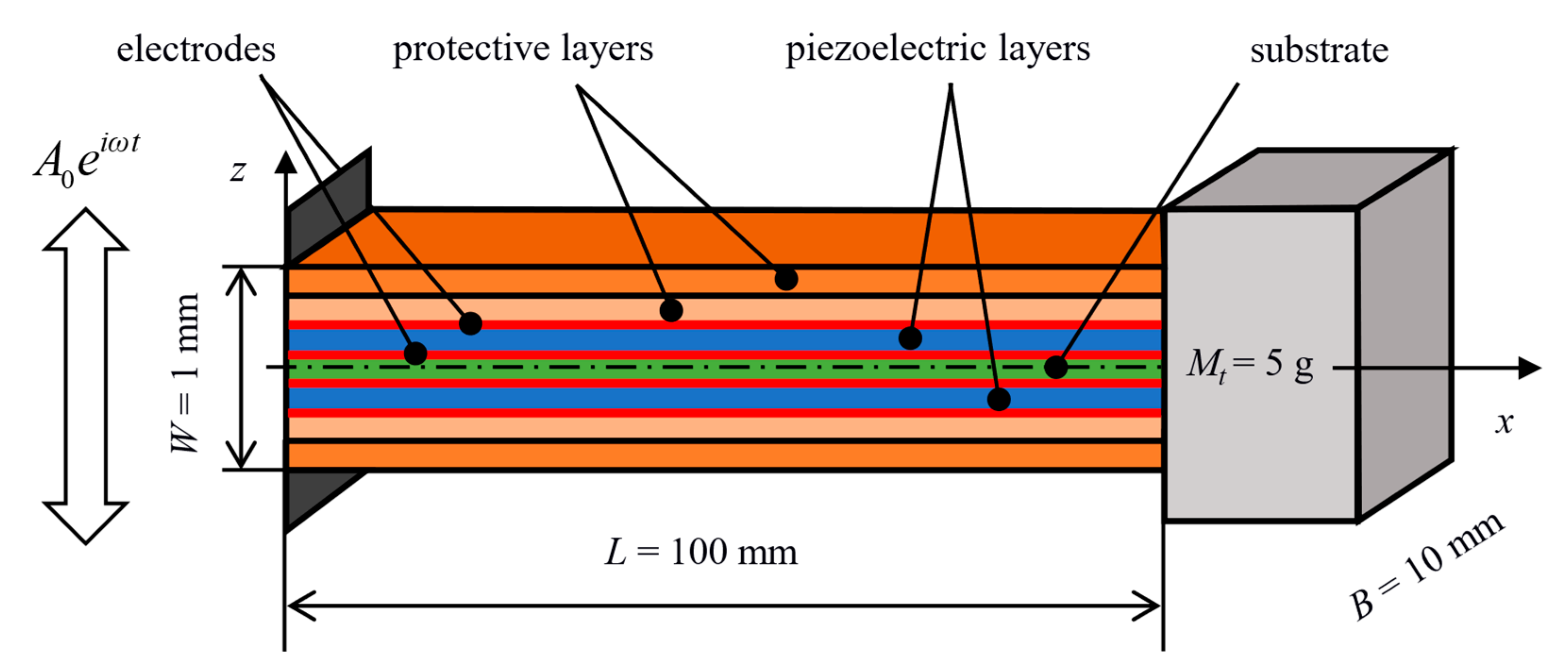
2. Bimorph Cantilever Beam Design

A bimorph configuration of a proposed piezoelectric energy harvester in the form of a geometrically symmetric multilayer ceramic structure is shown in Figure 2. This novel structure integrates protective ceramic layers on the outside of piezoelectric layers. The layers within the multilayer structure contain high thermal residual stresses which are induced upon manufacturing of the laminate due to a mismatch of thermal expansion coefficients of used materials. The basic idea of the multilayer design was firstly presented in the previous author’s work [24]. Unlike the traditional bimorph configuration (piezo–substrate–piezo) which is very prone to a brittle failure caused by unstable surface crack growth when excessively loaded, such a multilayer design with proper distribution of thermal residual stresses within the layers leads to a significant increase in the resistance of structure to surface crack propagation as presented in publications [25,26,27]. The residual stresses allow the multilayer harvester to withstand significantly higher mechanical loads (than traditional harvester designs) and simultaneously thus increase also the amount of generated electrical power.
As shown in Figure 2, the considered multilayer structure consists of seven layers: a substrate in the middle, a piezoelectric layer on each side of the substrate, followed by two protective layers. This number of layers was chosen to allow for a design of a relatively thin structure which is as compliant as possible. Dimensions of the structure were chosen to be L = 100 mm, B = 10 mm, and W = 1 mm. The free end also bears a tip mass Mt = 5 g. The piezoelectric layers are considered to be made from BaTiO3 and are electrically connected in parallel. The substrate together with protective layers are considered to be made from ZrO2 and ATZ (Alumina Toughened Zirconia). These materials were chosen due to their relatively close values of thermal expansion coefficient α and, as a consequence, moderate levels of thermal residual stresses σres are induced within the considered multilayer structure upon its fabrication. Material properties of the considered materials are listed in Table 1.

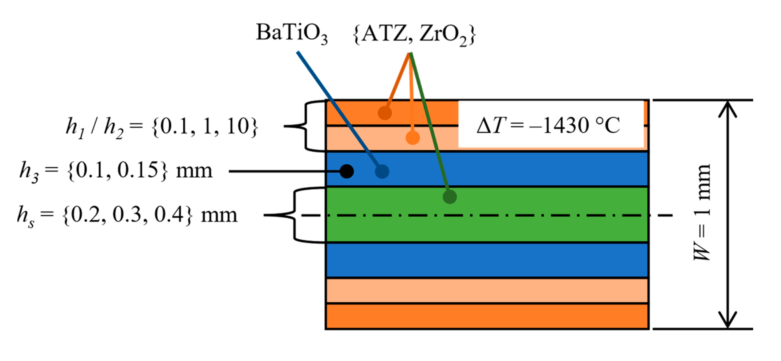
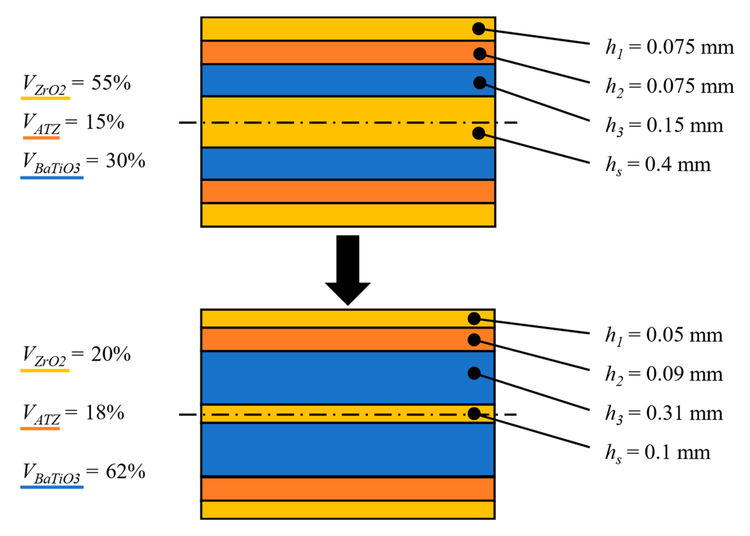
2.1. Optimization of the Layer Configuration within the Proposed Multilayer Structure

Individual layers of the multilayer structure need to have optimal thicknesses and materials without changing the total thickness of the structure in order to make the structure more resistant to a brittle failure via reasonably high levels of thermal residual stresses (induced upon the laminate fabrication). The aim of the optimization is to make the outer protective layers highly resistant to surface crack propagation to prevent potential surface cracks from expanding into the BaTiO3 layer, and thus causing a malfunction of the system. At the same time, BaTiO3 layers should be as thick as possible to minimise their capacitance so that the amount of generated electrical power is not suppressed.
Optimal thickness of each layer and sequence of used materials was sought similarly as in [24] to achieve both a reasonably low level of residual stresses σres within the layers and at the same time to obtain the highest possible resistance to surface crack propagation quantified with the so-called apparent fracture toughness [30]. The apparent fracture can be effectively calculated by employing the weight function method described in [31], evaluating the apparent fracture toughness using the distribution of thermal residual stresses within the layers and a so-called weight function. Upon calculation, the crack path is assumed to not be affected by thermal residual stresses (i.e., the crack is assumed to grow perpendicular to the structure’s surface). Thermal residual stresses σres, which are required for determining the apparent fracture toughness, can be quantified within i-th layer using relations from classical laminate theory [32] as:
σ r e s , i = E i 1 ν i ( α ¯ α i ) Δ T , where α ¯ = i = 1 N E i α i h i 1 ν i / i = 1 N E i h i 1 ν i
Here, Ei, νi, and αi is the elastic modulus, Poisson’s ratio and thermal expansion coefficient of the i-th layer respectively and ΔT is the temperature difference between the room and the zero-strain (reference) temperature. The term α ¯ represents the apparent thermal expansion coefficient of the whole laminate and hi is the thickness of the i-th layer. The distribution of σres is assumed to not be affected by piezoelectric properties of BaTiO3 layers. The apparent fracture toughness KR,eff can then be calculated using the weight function approach [31] as:
K R , e f f ( a ) = K c , 0 0 a h ( z , a ) σ r e s ( z ) d z
where Kc,0 is the intrinsic fracture toughness of current layer, a is the crack length, and h(z, a) is a weight function defined, e.g., in [33].
As stated above, the aim of the optimization is to achieve both highest possible values of KR,eff in the protective layers and at the same time keep the values of σres within the layers at a reasonably low level by changing thicknesses and material order of the substrate and protective layers without changing the total thickness of the structure. The optimization process was split into two phases. During the first phase which is schematically shown in Figure 3, the individual materials within outer protective layers and the substrate were changed from ATZ to ZrO2. The thickness ratio h1/h2 of the outer protective layers was changed in such a manner that either both layers were equally thick or one of them was significantly thicker. The thickness of BaTiO3 layers hp could take values from a discrete set {0.1, 0.15} mm and the thickness of substrate hs could take values from a discrete set {0.2, 0.3, 0.4} mm. The whole structure was subjected to a temperature change ΔT = −1430 °C. This value represents a common temperature difference between the zero-strain temperature and the room temperature [34]. The first phase showed that the best results which are presented in Figure 4, i.e., reasonably low level of thermal residual stresses and sufficiently high apparent fracture toughness in outer protective layers, are achieved when both outer protective layers are equally thick (h1/h2 = 1), BaTiO3 layers being 0.15 mm thick and ZrO2 substrate being 0.4 mm thick. Other combinations lead either to high thermal residual stresses within ATZ and BaTiO3 layers or no increase in apparent fracture toughness (KR,eff was not higher than the intrinsic fracture toughness Kc,0 of a particular material) of outer protective layers.
During the second phase of the optimization, the volumetric fractions Vi of used materials were changed so that the BaTiO3 layers were as thick as possible in order to reduce their capacitance. The resulting, optimised configuration is shown in Figure 5. ZrO2 layers including the substrate were made thinner to allow for thicker BaTiO3 layers due to their similar thermal expansion coefficients α.
As depicted in Figure 6a, for a temperature difference of ΔT = −1430 °C between zero-strain and room temperature we receive a composition with a relatively low level of tensile residual stresses of 141 MPa within BaTiO3 layers and high compressive stresses of −433 MPa in ATZ layers. The Figure 6b shows a significant increase of apparent fracture toughness in ATZ protective layers, compared with the intrinsic value of 3.2, the actual value of 11.73 means almost four-times improved resistance to unstable surface crack propagation. Note that the increase in thickness of BaTiO3 layers led to a much higher apparent fracture toughness in ATZ protective layers and substantially lower tensile residual stresses within BaTiO3 layers compared with the results from the first optimization phase (Figure 4).

3. 1DOF Model of Multilayer Piezoelectric Harvester

To determine the electromechanical response of the multilayer piezoelectric harvester, which is excited by ambient vibration with frequency ω, an appropriate computational model must be employed. The chosen dimensions of the considered harvester allow for applying the thin beam (Euler–Bernoulli) theory. Hence, if the beam is forced with a forcing frequency close to its first natural frequency ωr, its transverse displacement relative to the base w can be represented by its first, mass normalised, mode shape ϕ1 and a modal coordinate η as:
w ( x , t ) ϕ 1 ( x ) η ( t ) .
The first natural frequency ωr can be extracted from the following transcendental equation from [35]:
1 + cos λ 1 cosh λ 1 + λ 1 M t m L ( cos λ 1 sinh λ 1 sin λ 1 cosh λ 1 ) = 0
where Mt is the tip mass and m is mass of the composite beam per unit of its length which is simply defined as:
m = i = 1 N ρ i B h i
where N is a number of layers and ρi is a density of the i-th layer. λ1 is then defined as:
λ 1 2 = ω r m L 4 i = 1 N E i J i
where i = 1 N E i J i represents the bending stiffness of the composite beam as a sum of elastic modulus Ei and cross-sectional moment of inertia Ji of i-th layer referenced to the geometrical centre of the beam’s cross section. ϕ1 can then be extracted from:
ϕ 1 ( x ) = C 1 [ cos λ 1 L x cosh λ 1 L x + ς 1 ( sin λ 1 L x sinh λ 1 L x ) ]
where ς1 is defined as:
ς 1 = sin λ 1 sinh λ 1 + λ 1 M t m L ( cos λ 1 cosh λ 1 ) cos λ 1 + cosh λ 1 λ 1 M t m L ( sin λ 1 sinh λ 1 )
C1 in (7) represents a modal amplitude constant which should be evaluated from (9) so that the first mode shape is mass normalised:
0 L ϕ 1 ( x ) m ϕ 1 ( x ) d x + ϕ 1 ( L ) M t ϕ 1 ( L ) = 1 .
Then, since the considered multilayer harvester can be classified as a bimorph with added protective layers whose piezoelectric layers are connected electrically in parallel, one can utilise the single degree-of-freedom computational model from [35] whose governing equations are:
η ¨ ( t ) + 2 b r ω r η ˙ ( t ) + ω r 2 η ( t ) + κ U ( t ) = f ( t )
C p U ˙ ( t ) + U ( t ) R l = κ η ˙ ( t )
where br is a damping ratio, κ is the modal electromechanical coupling term, U is the voltage drop generated in piezoelectric layers, f is the modal forcing function, Cp is the capacitance of piezoelectric layers, and Rl is connected resistive load. κ is in [35] defined as:
κ = 2 e 31 B h p + h s 2 d ϕ 1 ( x ) d x | x = L
where e31 is piezoelectric modulus of BaTiO3 e 31 = E d 31 , hp is the thickness of BaTiO3 layers, and hs is the thickness of the substrate. Next, f is defined as:
f ( t ) = A 0 [ m 0 L ϕ 1 ( x ) d x + M t ϕ 1 ( L ) ] e i ω t
where A0 is the acceleration amplitude of kinematic excitation. Cp is simply defined as:
C p = 2 ϵ 33 S B L h p
where ϵ 33 S is a permittivity of the BaTiO3 measured at constant mechanical strain and defined as ϵ 33 S = ϵ 33 T d 31 e 31 .
Equations (10) and (11) can be modified for direct calculation of the relative beam’s free end displacement w(L) by rewriting (3) into:
η ( t ) = w ( L , t ) ϕ 1 ( L )
By substituting (15) into (10) and (11) we obtain a following system of ODEs with unknowns being w(L, t) and U(t)
m e f f w ¨ ( L , t ) + b e f f w ˙ ( L , t ) + k e f f w ( L , t ) + θ U ( t ) = m a c c z ¨ ( t )
U ˙ ( t ) = 1 C p ( θ w ˙ ( L , t ) U ( t ) R l )
where m e f f = 1 ϕ 1 ( L ) represents effective mass of the harvester, b e f f = 2 b r ω r ϕ 1 ( L ) is effective damping, k e f f = ω r 2 ϕ 1 ( L ) is effective stiffness of the beam, θ = κ ϕ 1 ( L ) = 2 e 31 B h p + h s 2 d ϕ 1 ( x ) d x | x = L ϕ 1 ( L ) is effective electromechanical coupling factor, m a c c = m ( z 0 0 L ϕ 1 ( x ) d x ) + M t ϕ 1 ( L ) z 0 is acceleration mass coefficient for calculation of effective force from the base acceleration, and z ¨ = A 0 e i ω t is the base acceleration.
Equations (16) and (17) use relative transverse displacement w as a function of time and position on the beam’s centreline to completely describe the centreline’s deformed shape. The 1DOF model uses only the tip displacement, therefore Equations (16) and (17) can be simplified with a substitution q(t) = w(L, t) where q(t) is the tip displacement as a function of time. This substitution leads to a common form of (16) and (17) which is used to simulate the electro-mechanical behaviour of a cantilever beam piezoceramic energy harvester:
m e f f q ¨ ( t ) + b e f f q ˙ ( t ) + k e f f q ( t ) + θ U ( t ) = m a c c z ¨ ( t )
U ˙ ( t ) = 1 C p ( θ q ˙ ( t ) U ( t ) R l )
Using the ODE system of a coupled electro-mechanical device (18) and (19), a Simulink model was created to simulate the behaviour of a multilayer cantilever beam under base excitation. Calculated coefficients of 1DOF coupled electro-mechanical model used in the simulation are written in Table 2. This model of a novel multilayer structure with crack protective layers can be used to design an extended model of a bistable vibration energy harvester with additional magnets. A similar 1DOF model was explained and experimentally verified in publication [36].

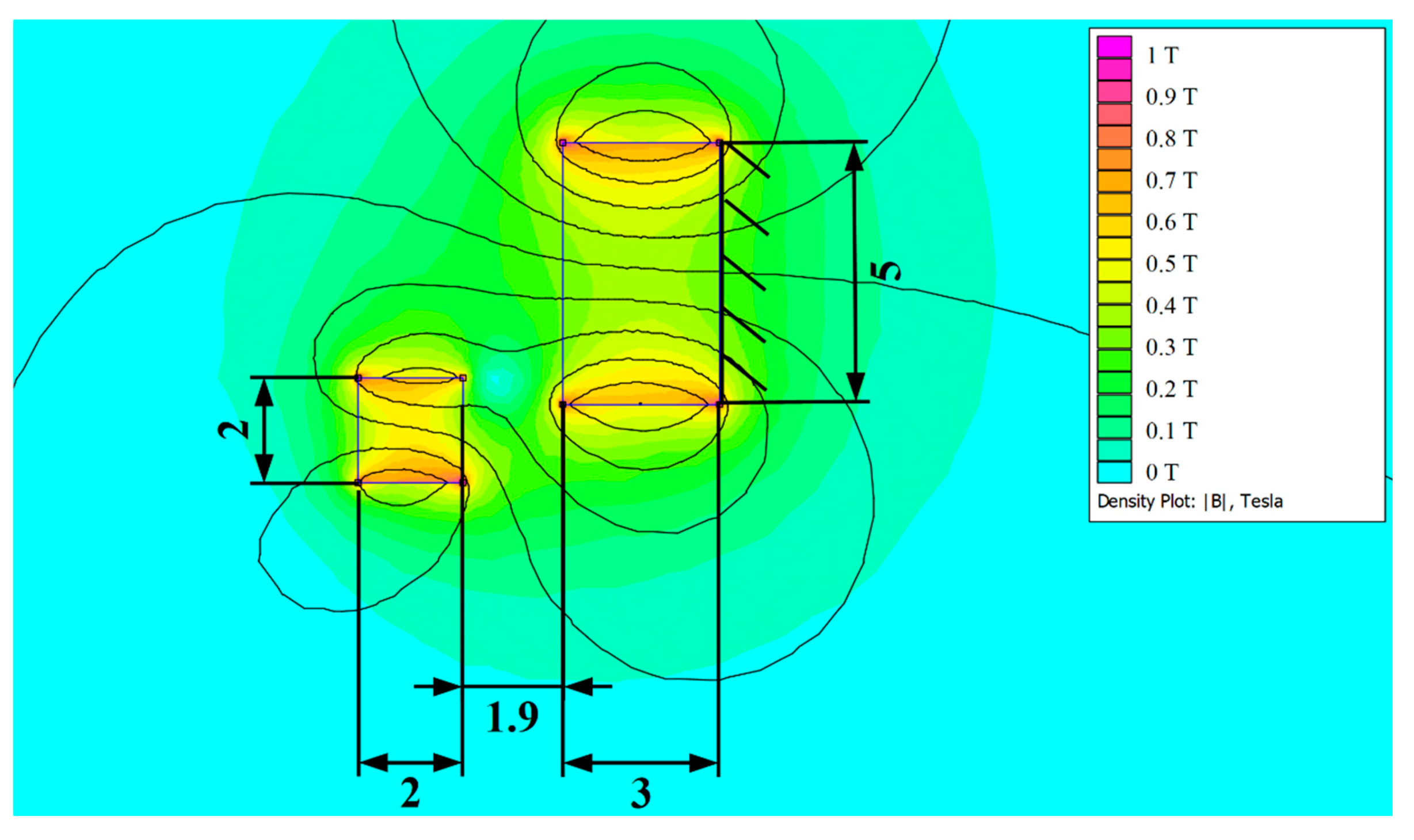
4. Design of Auxiliary Magnetic Spring and Model of Bistable Energy Harvester

The presented well-known system of auxiliary magnets provides a tailor-made design of a kinetic energy harvester based on the novel lead-free cantilever with protective layers. The main aim of this system is to present energy harvesting potential of the novel architecture design with crack protective layers. The used auxiliary magnetic system for a bistable energy harvester consists of an oscillating tip mass permanent magnet and a fixed permanent magnet. The system made use of rare earth magnets FeNB provides a magnetic spring in repulsive direction, which is commonly used to provide nonlinear behaviour to a wider bandwidth of vibration energy harvester. The topology of a bistable piezoceramic energy harvester is depicted in Figure 7. This device consists of the novel BaTiO3 piezoceramic layers (Section 2.1) and the auxiliary magnetic system which are analysed and designed for maximal effectivity of harvested power, exactly for the presented BaTiO3 architecture.
The presented linear behaviour of ODE coupled electro-mechanical system (18) and (19) is extended by nonlinear magnetic forces of the auxiliary magnetic system in Figure 7. The analysed magnetic force is a function of the tip mass displacement q. This magnetic force can be interpreted as a variable stiffness and together with the linear beam’s stiffness keff, it is summed with the nonlinear force from magnets, resulting in the total force. This resultant force affects the vibrations of the considered energy harvester and allow for calculation of oscillator’s potential energy via this resultant force.
Software FEMM 4.2 was used to calculate the magnetic force of the auxiliary magnetic system. This finite element method software can simulate the in-plane magnetic field, and thus calculate the force acting on the magnet. Results of the calculation of the magnetic field are demonstrated in Figure 8. The vertical component of the magnetic force is used in the ODE model (18). The horizontal component of the force is not considered, since it is compensated by the beam’s clamping and it does not affect the oscillations and electro-mechanical conversion.
Dimensions of the permanent magnets and the displacement between them modifies the magnetic force. An important indicator, or one could say a cost function, to design parameters is not this magnetic force, but the total force produced through summation of the magnetic force with the elastic force of the beam (Fbeam = keff.q). The total force is the main characteristic that might be used to estimate the behaviour of the energy harvester. It could provide stable behaviour with a hardening or softening characteristic, or bistable behaviour.
In this research, the bistable behaviour was the goal of auxiliary magnets design. The bistability might provide various operational modes, which are useable in energy harvesting [23]. The barrier between both stable positions is important in bistable design of energy harvester. If the barrier is high, the harvester oscillates around one stable position and does not change to the second one. Lower barrier might often cause repeated swinging between two stable positions. To illustrate the difference, Figure 9 compares a nonlinear oscillator with high and low barrier.
Nonlinear oscillator with low barrier seems to be more sufficient for energy harvesting. Swinging between two stable positions could bring more energy than oscillation around one stable position. Due to this fact, magnets were designed to produce this type of bistability with a low barrier. Design parameters were dimensions of magnets and distance between them. The final design of the magnetic system is demonstrated in Figure 10.
These designed auxiliary magnets produce bistable characteristic with low barrier, depicted in Figure 11. Behaviour of the designed system is modelled with Equations (18) and (19) from the previous section extended with the magnetic force represented as a nonlinear function of the tip displacement. The final system is described by these extended equations:
m e f f q ¨ ( t ) + b e f f q ˙ ( t ) + k e f f q ( t ) + F m a g ( q ) + θ U ( t ) = m a c c z ¨ ( t )
U ˙ ( t ) = 1 C p ( θ q ˙ ( t ) U ( t ) R l )
where Fmag is the force from auxiliary magnets, the same as in Figure 11.

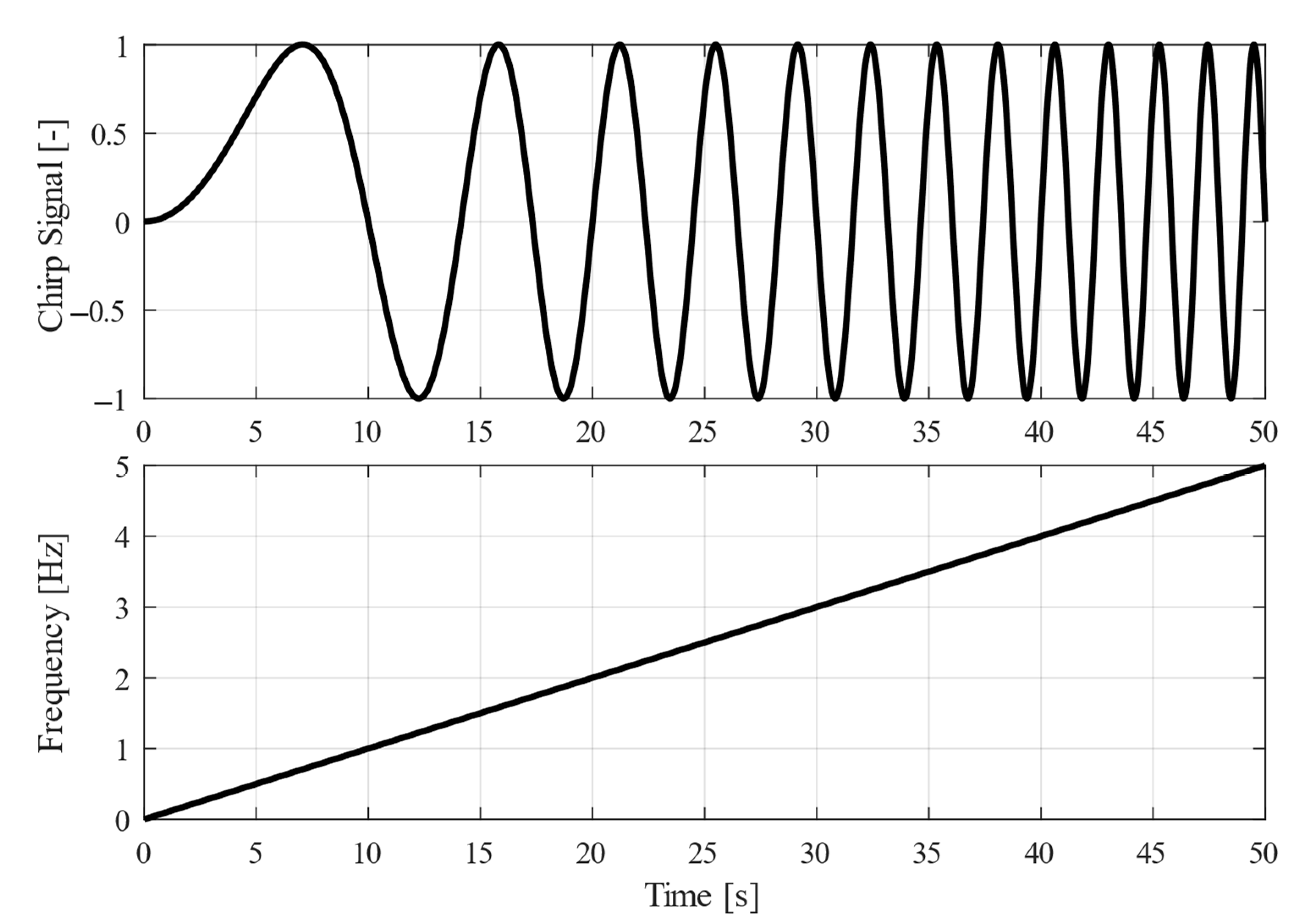
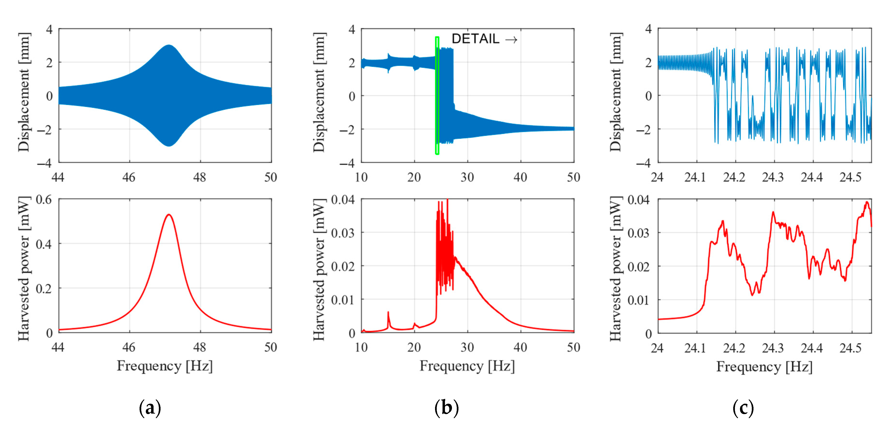
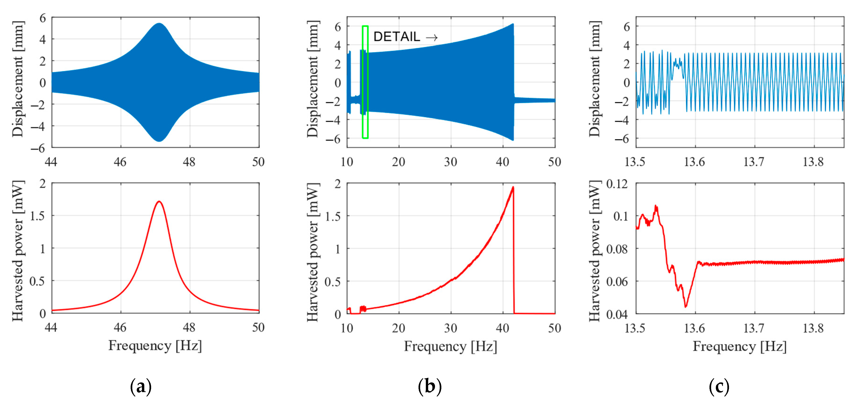
5. Simulation Results

The designed bistable energy harvesting system of the novel multilayer beam with auxiliary magnets was simulated to estimate its dynamic behaviour and to estimate the crack protection safety. The ambient excitation was modelled in a form of a chirp signal, which is a sine function with a constant amplitude and continuously changing frequency. The chirp signal is demonstrated in Figure 12. Parameters for the simulation are the initial frequency, the final frequency and the speed of change in frequency. The speed of change should be low enough to produce quasi stabilised oscillations. In these simulations, the changing frequency speed was 0.1 Hz/s.
The designed vibrational energy harvester (VEH) was tested with varying amplitude of vibrations to estimate the optimal operating range. Figure 13 depicts results from simulation with excitation amplitude 0.5 g, comparing the nonlinear (b) and linear (a) version, and the detail of oscillation between stable positions (c). The displacement plot is a direct tip displacement from the simulations. The harvested power is a moving average power calculated from the actual power on the resistor. The actual power is simply calculated from the voltage on the resistor and the resistance value bas follows:
P = 1 2 U ( t ) 2 R l .
The linear energy harvester has a higher power output with a maximum of 0.5 mW for 47 Hz. The nonlinear one has a lower power about 0.03 mW, however, it has a wider frequency range—from 25 to 35 Hz. Depending on the application, the nonlinear energy harvester might be used with an advantage to harvest energy from frequency changes in this range. The linear one can only harvest energy near its resonance of 47 Hz. However, one can say that at this amplitude of vibrations the nonlinear VEH does not bring a significant improvement.
On the other hand, the situation is completely different with a higher amplitude of excitation acceleration. Figure 14 represents operation with the excitation amplitude 0.9 g. The linear VEH has the same operation frequency 47 Hz and maximal power 1.8 mW. The nonlinear one has a wide operational range from about 20 to 42 Hz, where the power varies from the 0.2 to 2 mW. The maximum power of the nonlinear energy harvester is higher than of the linear one and also the operating range is wider. The nonlinear VEH brings a strong improvement for the amplitude of ambient vibrations: wider operational range and a higher amplitude. However, the important question in this part is the safety of the structure against the propagation of potential surface crack.

6. Estimation of Critical Tip Displacement Amplitude

The critical displacement of the beam’s free end is such a displacement amplitude upon which a potential surface crack propagates through the BaTiO3 layer, and thus causes a malfunction of the whole multilayer structure. To determine critical displacement amplitude of the harvester’s free end, the stress intensity factor Kappl at the tip of the crack within ATZ protective layers upon vibrations must not be higher than 11.7 MPa·m0.5 (see the end of Section 2.1). The stress intensity factor Kappl is defined through the weight function method as:
K a p p l ( a ) = 0 a h ( z , a ) σ x 0 ( z ) d z ,
where h(z, a) is a weight function defined in [33] and σx0(z) is the amplitude of bending stress distribution within the multilayer structure. The highest values of bending stress upon vibrations consisting solely of the first mode shape are found in the vicinity of the clamping at x = 0, which is, therefore, the most suitable location for potential surface cracks. The amplitude of bending stress distribution σx0(z) is, in the case of heterogenous multilayer structure, a layer-wise function and near the clamping at x = 0, it can be expressed in individual layers as:
σ x 0 , i ( z ) = E i d 2 w ( x ) d x 2 | x = 0 | z | ,
where subscript i denotes the i-th layer. Since the bending stress σx0(z) and stress intensity factor Kappl are assumed to vary linearly with the beam tip displacement, one can easily estimate the critical tip displacement amplitude using a safety factor kBF defined as:
k B F = K R , e f f ( a A T Z ) K a p p l ( a A T Z ) ,
where aATZ is the location of ATZ/BaTiO3 interface. If the calculated safety factor kBF is equal or lower than 1, then a potential surface crack will propagate through both protective layers and cause a brittle fracture of the whole multilayer structure.
For the results given in Section 5. where the harvester is kinematically excited with an acceleration amplitude of 0.9 g and its free end vibrates with a displacement total amplitude of 6 mm the amplitude of the bending stress within individual layers is shown in Figure 15a. The maximal stress values occur in ATZ layers since it is the stiffest material within the laminate. Figure 15b shows the corresponding stress intensity factor Kappl along with the apparent fracture toughness KR,eff calculated in Section 2.1. The stress intensity factor Kappl reaches the value of 7MPa·m0.5 at ATZ/BaTiO3 interface which gives a safety factor of 1.67. Therefore, the critical amplitude of the free end’s displacement upon which a brittle fracture occurs is approximately 10 mm. This means a significant increase in resistance against the surface crack propagation compared to a typical harvester from [10] whose critical amplitude of the free end displacement is about 3 mm.

7. Discussion

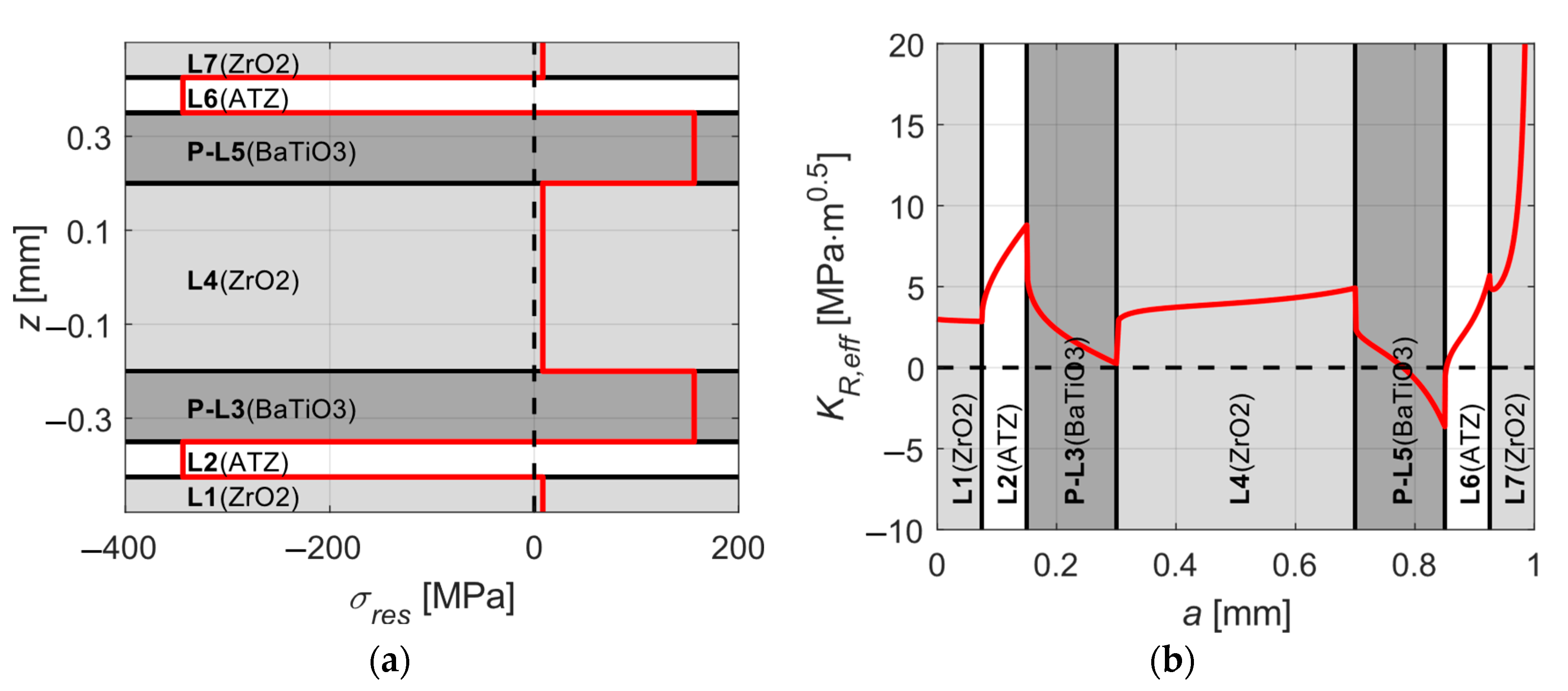
7.1. Effect of the Protective Layers

As shown in Section 2, the presented multilayer design of a piezoelectric harvester with high thermal residual stresses significantly increases the resistance to unstable surface crack propagation. In practice, this means that such a multilayer structure can withstand much larger deflections than its traditional counterparts having no protective layers with thermal compressive residual stresses.
On the other hand, as can be seen from Table 1, materials considered for protective layers commonly have higher elastic modulus than piezoelectric materials. If layers with such stiffer materials are too thick it may significantly increase the bending stiffness of the composite beam(which is undesirable for energy harvesting applications, since it lowers the amount of generated electrical power) and contrary when too thin protective layers are considered, the apparent fracture toughness of the structure is increased just slightly [32].
Therefore, the key task is to find a compromise between a very thin beam, which is desirable for energy harvesting applications but very prone to brittle failure, and a beam with thicker protective layers, which increase the beam’s resistance to unstable surface crack propagation but also significantly increase its bending stiffness, and thus lower the amount of generated electrical power.
Design used in this work was optimised to maximise the resistance to unstable surface crack propagation in the presented bistable operational mode. Thanks to this design, the critical tip displacement amplitude was simulated up to 15 mm peak to peak operation without a brittle fracture. Theoretically, the maximal tip displacement amplitude was increased to 10 mm (20 mm peak-to-peak) compared with the tip displacement amplitude of the VEH from [10] without protective layers, for which the cracking occurs at a tip displacement amplitude around 4 mm. The designed BaTiO3 beam without the protective layer might have critical tip displacement around 1 mm, which means about 10 times higher crack resistivity with layered architecture than without it.

7.2. PZT Solution vs. Proposed Lead-Free Design

In comparison with PZT energy harvesters, the designed lead-free harvester generates lower power due to significantly lower piezoelectric parameters. Commonly used commercial solution Midé V21BL [37] in the resonance operation frequency 40 Hz provides maximal power 0.9 mW upon excitation of 0.5 g. Presented and designed lead-free harvester provides output power around 0.5 mW, operated at 47 Hz for the same excitation of 0.5 g. Dimension of the Midé solution is 64 mm in length with a tip mass 4.8 g. The designed lead-free VEH is 100 mm long with a tip mass 5 g. The resonance frequencies are a slightly different, and this difference could be compensated by longer beam or thinner piezoceramic layers which decrease the natural frequency.

7.3. Effect of the Auxiliary Magnets Producing Nonlinear Behaviour

The nonlinear behaviour produced by the auxiliary magnets allows to bring a wider operating bandwidth and a higher maximal power. It is obvious that the linear energy harvester operates in one frequency with various amplitudes of excitation vibrations, whereas the nonlinear one operates in a threshold amplitude of excitation vibrations for a wide bandwidth, but for a lower amplitude, so its operation is unsuitable for the energy harvesting, since the generated power is very low.

8. Conclusions

In this article, the idea of crack protective layers was used to design the lead-free cantilever beam, which allows for higher amplitudes of oscillations, and thus to increase also the harvested power. The common lead-free BaTiO3 bimorph cantilever can only operate in low amplitudes of the excited oscillations due to a very brittle behaviour. The proposed design of a lead-free cantilever with protective layers allows to use this design for operation in an extended bistable system with significantly higher amplitudes. Due to the implementation of the proposed cantilever design, the auxiliary magnets were used to produce the energy harvesting system with two extended equilibrium distance of bistable system. Furthermore, the stress intensity factor at the tip of potential surface crack in the system, calculated for the maximal displacement demonstrates that the designed architecture is more resistant to surface crack propagation in the simulated operational range.
Designed and presented bistable kinetic energy harvester has lower electric outputs than commercial PZT energy harvesters. However, used BaTiO3 material is lead-free, which is very important recently. Moreover, the proposed design is improved by the protective layers allowing higher excitation amplitudes for which the power is just 50% lower than at commercial PZT solutions.
Manufacturing of the proposed composite structure is now under development and the manufacturing process and characterization of materials are published in papers [4,38,39]. The main aim of our future development is the realization of the experiment and to comspare obtained experimental results with other bistable PZT energy harvesting system.
The presented design of a bistable nonlinear system provides operation in a wide frequency bandwidth for an excitation amplitude close to 1 g. The effect of the nonlinearity is disputable for the low amplitude of vibrations. However, for the excitation amplitude around 1 g, the operational frequency bandwidth is in range from 20 to 40 Hz, what can be useful in some engineering application. The harvested power lies in the range between 0.2 and 2 mW, depending on the excitation frequency. The highest power of 2 mW could be used e.g. to power up some remote sensors with wireless data transfer. The presented approach brings this bistable energy harvesting technology near to its application in a data acquisition.

Author Contributions

Conceptualization, Z.H. and O.R.; methodology, Z.M.; software, Z.M. and O.R.; validation, O.S., Z.M., and Z.H.; formal analysis, O.R.; investigation, O.R.; resources, Z.H. and O.R.; writing—original draft preparation, Z.H., Z.M., O.S., and O.R.; writing—review and editing, O.S.; visualization, Z.M. and O.R.; supervision, Z.H. and O.S.; project administration, Z.H.; funding acquisition, Z.H. All authors have read and agreed to the published version of the manuscript.

Funding

This paper has been financially supported by the project “Novel material architectures for SMART piezoceramic electromechanical converters” GACR 17-08153S under the Czech Science Foundation.

Conflicts of Interest

The authors declare no conflict of interest. The funders had no role in the design of the study; in the collection, analyses, or interpretation of data; in the writing of the manuscript, or in the decision to publish the results.

References

  1. Caliò, R.; Rongala, U.; Camboni, D.; Milazzo, M.; Stefanini, C.; de Petris, G.; Oddo, C. Piezoelectric Energy Harvesting Solutions. Sensors 2014, 14, 4755–4790. [Google Scholar] [CrossRef] [PubMed] [Green Version]
  2. Bowen, C.R.; Kim, H.A.; Weaver, P.M.; Dunn, S. Piezoelectric and ferroelectric materials and structures for energy harvesting applications. Energy Environ. Sci. 2014, 7, 25. [Google Scholar] [CrossRef] [Green Version]
  3. Maurya, D.; Peddigari, M.; Kang, M.-G.; Geng, L.D.; Sharpes, N.; Annapureddy, V.; Palneedi, H.; Sriramdas, R.; Yan, Y.; Song, H.-C.; et al. Lead-free piezoelectric materials and composites for high power density energy harvesting. J. Mater. Res. 2018, 33, 2235–2263. [Google Scholar] [CrossRef] [Green Version]
  4. Tofel, P.; Machu, Z.; Chlup, Z.; Hadraba, H.; Drdlik, D.; Sevecek, O.; Majer, Z.; Holcman, V.; Hadas, Z. Novel layered architecture based on Al2O3/ZrO2/BaTiO3 for SMART piezoceramic electromechanical converters. Eur. Phys. J. Spec. Top. 2019, 228, 1575–1588. [Google Scholar] [CrossRef]
  5. Bai, Y.; Matousek, A.; Tofel, P.; Bijalwan, V.; Nan, B.; Hughes, H.; Button, T.W. (Ba,Ca)(Zr,Ti)O3 lead-free piezoelectric ceramics—The critical role of processing on properties. J. Eur. Ceram. Soc. 2015, 35, 3445–3456. [Google Scholar] [CrossRef]
  6. Sappati, K.K.; Bhadra, S. Piezoelectric polymer and paper substrates: A review. Sensors 2018, 18, 3605. [Google Scholar] [CrossRef] [PubMed] [Green Version]
  7. Khaligh, A. Kinetic Energy Harvesting Using Piezoelectric and Electromagnetic Technologies—State of the Art. IEEE Trans. Ind. Electron. 2010, 57, 850–860. [Google Scholar] [CrossRef]
  8. Hadas, Z.; Smilek, J.; Rubes, O. Analyses of electromagnetic and piezoelectric systems for efficient vibration energy harvesting. In Proceedings of the Volume 10246, Smart Sensors, Actuators, and MEMS VIII, Barcelona, Spain, 8–10 May 2017; Fonseca, L., Prunnila, M., Peiner, E., Eds.; p. 1024619. [Google Scholar]
  9. Gljušćić, P.; Zelenika, S.; Blažević, D.; Kamenar, E. Kinetic energy harvesting for wearable medical sensors. Sensors 2019, 19, 4922. [Google Scholar] [CrossRef] [Green Version]
  10. Bai, Y.; Tofel, P.; Hadas, Z.; Smilek, J.; Losak, P.; Skarvada, P.; Macku, R. Investigation of a cantilever structured piezoelectric energy harvester used for wearable devices with random vibration input. Mech. Syst. Signal Process. 2018, 106, 303–318. [Google Scholar] [CrossRef] [Green Version]
  11. Qing, X.; Li, W.; Wang, Y.; Sun, H. Piezoelectric transducer-based structural health monitoring for aircraft applications. Sensors 2019, 19, 545. [Google Scholar] [CrossRef]
  12. Ambrosio, R.; Jimenez, A.; Mireles, J.; Moreno, M.; Monfil, K.; Heredia, H. Study of Piezoelectric Energy Harvesting System Based on PZT. Integr. Ferroelectr. 2011, 126, 77–86. [Google Scholar] [CrossRef]
  13. Rubes, O.; Brablc, M.; Hadas, Z. Verified nonlinear model of piezoelectric energy harvester. In Proceedings of the MATEC Web of Conferences, Wuhan, China, 10–12 November 2018; Volume 211. [Google Scholar]
  14. Sebald, G.; Kuwano, H.; Guyomar, D.; Ducharne, B. Experimental Duffing oscillator for broadband piezoelectric energy harvesting. Smart Mater. Struct. 2011, 20, 102001. [Google Scholar] [CrossRef]
  15. Litak, G.; Friswell, M.I.; Adhikari, S. Magnetopiezoelastic energy harvesting driven by random excitations. Appl. Phys. Lett. 2010, 96, 214103. [Google Scholar] [CrossRef]
  16. Rubes, O.; Hadas, Z. Designing, modelling and testing of vibration energy harvester with nonlinear stiffness. In Proceedings of the SPIE—The International Society for Optical Engineering, Anaheim, CA, USA, 9–13 April 2017; Volume 10246. [Google Scholar]
  17. Gao, Y.J.; Leng, Y.G.; Fan, S.B.; Lai, Z.H. Performance of bistable piezoelectric cantilever vibration energy harvesters with an elastic support external magnet. Smart Mater. Struct. 2014, 23, 095003. [Google Scholar] [CrossRef]
  18. Ferrari, M.; Ferrari, V.; Guizzetti, M.; Andò, B.; Baglio, S.; Trigona, C. Improved energy harvesting from wideband vibrations by nonlinear piezoelectric converters. Sensors Actuators A Phys. 2010, 162, 425–431. [Google Scholar] [CrossRef] [Green Version]
  19. Litak, G.; Friswell, M.I.; Adhikari, S. Regular and chaotic vibration in a piezoelectric energy harvester. Meccanica 2015, 51, 1017–1025. [Google Scholar] [CrossRef] [Green Version]
  20. Harne, R.L.; Wang, K.W. Prospects for Nonlinear Energy Harvesting Systems Designed Near the Elastic Stability Limit When Driven by Colored Noise. J. Vib. Acoust. 2014, 136, 021009. [Google Scholar] [CrossRef]
  21. Rubes, O.; Hadas, Z. Design and Simulation of Bistable Piezoceramic Cantilever for Energy Harvesting from Slow Swinging Movement. In Proceedings of the—2018 IEEE 18th International Conference on Power Electronics and Motion Control, PEMC 2018, Budapest, Hungary, 26–30 August 2018; pp. 663–668. [Google Scholar]
  22. Erturk, A.; Hoffmann, J.; Inman, D.J. A piezomagnetoelastic structure for broadband vibration energy harvesting. Appl. Phys. Lett. 2009, 94, 254102–254105. [Google Scholar] [CrossRef]
  23. Zhang, X.; Yang, W.; Zuo, M.; Tan, H.; Fan, H.; Mao, Q.; Wan, X. An arc-shaped piezoelectric bistable vibration energy harvester: Modeling and experiments. Sensors 2018, 18, 4472. [Google Scholar] [CrossRef] [Green Version]
  24. Majer, Z.; Ševeček, O.; Machů, Z.; Štegnerová, K.; Kotoul, M. Optimization of Design Parameters of Fracture Resistant Piezoelectric Vibration Energy Harvester; Trans Tech Publications Ltd.: Schwiz, Switzerland, 2018; Volume 774, ISBN 9783035713503. [Google Scholar]
  25. SGLAVO, V.; BERTOLDI, M. Design and production of ceramic laminates with high mechanical resistance and reliability. Acta Mater. 2006, 54, 4929–4937. [Google Scholar] [CrossRef]
  26. Maca, K.; Pouchly, V.; Drdlik, D.; Hadraba, H.; Chlup, Z. Dilatometric study of anisotropic sintering of alumina/zirconia laminates with controlled fracture behaviour. J. Eur. Ceram. Soc. 2017, 37, 4287–4295. [Google Scholar] [CrossRef]
  27. Chang, Y.; Bermejo, R.; Ševeček, O.; Messing, G.L. Design of alumina-zirconia composites with spatially tailored strength and toughness. J. Eur. Ceram. Soc. 2015, 35, 631–640. [Google Scholar] [CrossRef]
  28. Bermejo, M.R. Structural Integrity of Alumina-Zirconia Multilayered Ceramics. Ph.D. Thesis, Universitat Politecnica de Catalunya, Barcelona, Spain, 2006. [Google Scholar]
  29. MatWeb BaTiO3 Datasheet. 2019. Available online: http://www.matweb.com/search/datasheet.aspx?matguid=216d8486b52746f88d8aad6f667720a0&ckck=1 (accessed on 1 June 2019).
  30. Fett, T.; Diegele, E.; Munz, D.; Rizzi, G. Weight functions for edge cracks in thin surface layers. Int. J. Fract. 1996, 81, 205–215. [Google Scholar] [CrossRef]
  31. Bueckner, H.F. Novel principle for the computation of stress intensity factors. Z. Fuer Angew. Math. Mech. 1970, 50, 529. [Google Scholar]
  32. Sestakova, L.; Bermejo, R.; Chlup, Z.; Danzer, R. Strategies for fracture toughness, strength and reliability optimisation of ceramic-ceramic laminates. Int. J. Mater. Res. 2011, 102, 613–626. [Google Scholar] [CrossRef]
  33. Fett, T.; Munz, D.; Yang, Y.Y. Applicability of the extended Petroski–Achenbach weight function procedure to graded materials. Eng. Fract. Mech. 2000, 65, 393–403. [Google Scholar] [CrossRef]
  34. Ševeček, O.; Kotoul, M.; Leguillon, D.; Martin, E.; Bermejo, R. Understanding the edge crack phenomenon in ceramic laminates. Frat. Integrita Strutt. 2015, 9, 362–370. [Google Scholar]
  35. Erturk, A. Electromechanical Modeling of Piezoelectric Energy Harvesters; Virginia Tech: Blacksburg, VA, USA, 2009. [Google Scholar]
  36. Rubes, O.; Brablc, M.; Hadas, Z. Nonlinear vibration energy harvester: Design and oscillating stability analyses. Mech. Syst. Signal Process. 2018, 125, 170–184. [Google Scholar] [CrossRef]
  37. Rubes, O.; Brablc, M.; Hadas, Z. Verified Nonlinear Model of Piezoelectric Energy Harvester. In Proceedings of the VETOMAC 2018, Lisbon, Portugal, 10–13 September 2018. [Google Scholar]
  38. Hadraba, H.; Chlup, Z.; Drdlík, D.; Šiška, F. Characterisation of mechanical and fracture behaviour of Al2O3/ZrO2/BaTiO3 laminate by indentation. J. Eur. Ceram. Soc. 2020, 40, 4799–4807. [Google Scholar] [CrossRef]
  39. Drdlik, D.; Chlup, Z.; Hadraba, H.; Drdlikova, K. Surface roughness improvement of near net shaped alumina by EPD. J. Aust. Ceram. Soc. 2020, 56, 721–727. [Google Scholar] [CrossRef]
Figure 1. A crack in piezoceramic layer due to operation in high oscillation amplitude (@ 4 mm).
Sensors 20 05808 g001
Figure 2. The considered multilayer piezoelectric harvester.
Sensors 20 05808 g002
Figure 3. Scheme of the first optimization phase.
Sensors 20 05808 g003
Figure 4. A ZrO2–ATZ (Alumina Toughened Zirconia)–BaTiO3 composition after the first phase optimization: (a) distribution of thermal residual stresses within the layers and (b) the apparent fracture toughness.
Sensors 20 05808 g004
Figure 5. The second phase of optimization showing the input configuration from the first optimization phase (top) and the resulting ideal layer composition for the multilayer piezoelectric harvester (bottom).
Sensors 20 05808 g005
Figure 6. The calculated outcome for the ideal layer configuration loaded with ΔT = −1430 °C: (a) Distribution of thermal residual stresses within the layers. (b) The apparent fracture toughness of the structure.
Sensors 20 05808 g006
Figure 7. Topology of used auxiliary magnets fixed on the novel multilayer piezoelectric cantilever beam.
Sensors 20 05808 g007
Figure 8. Magnetic Field Simulation of Auxiliary Magnets in Software FEMM 4.2.
Sensors 20 05808 g008
Figure 9. The magnetic force and potential energy in bistable oscillator with (a) huge barrier and (b) low barrier between two stable positions.
Sensors 20 05808 g009
Figure 10. Final design of the Auxiliary Magnetic System; dimensions are in (mm). The depth is 10 mm.
Sensors 20 05808 g010
Figure 11. (a) Final stiffness force and (b) potential energy of the designed oscillator.
Sensors 20 05808 g011
Figure 12. Chirp signal used for simulations.
Sensors 20 05808 g012
Figure 13. Sweep up with amplitude 0.5 g. (a) Linear, (b) nonlinear oscillator, and (c) detail of nonlinear oscillatations.
Sensors 20 05808 g013
Figure 14. Sweep up with amplitude 0.9 g. (a) Linear, (b) nonlinear oscillator, and (c) detail of nonlinear oscillations.
Sensors 20 05808 g014
Figure 15. (a) Amplitude of the bending stress within the laminate kinematically excited with an amplitude of 0.9 g. (b) Stress intensity factor Kappl (blue solid curve) corresponding to excitation amplitude 0.9 g and the apparent fracture toughness KR,eff (red dashed curve); brittle fracture of the whole structure occurs if Kappl > KR,eff in ATZ layer, i.e., if the blue solid curve appears in the red-filled area.
Sensors 20 05808 g015
Table 1. Mechanical and piezoelectric properties of used materials [24,28,29].
Materialρ
(kg/m3)
E
(GPa)
ν
(–)
α
(ppm/K)
Kc,0 (MPa·m0.5)d31
(C/N)
ϵ 33 T / ϵ 0
(–)
Sensors 20 05808 i001ATZ40503900.229.83.2
Sensors 20 05808 i002ZrO256802100.3110.33
Sensors 20 05808 i003BaTiO36020700.2211.50.7–58·10-121250
Table 2. 1DOF model parameters of the considered multilayer beam.
meff
(g)
beff
(Ns/m)
keff
(N/m)
macc
(g)
Cp
(nF)
θ
(μN/V)
Rl
(kΩ)
6.33.75·10-2555.87.175.624545

