A CMM-Based Method of Control Point Position Calibration for Light Pen Coordinate Measuring System
Abstract
1. Introduction
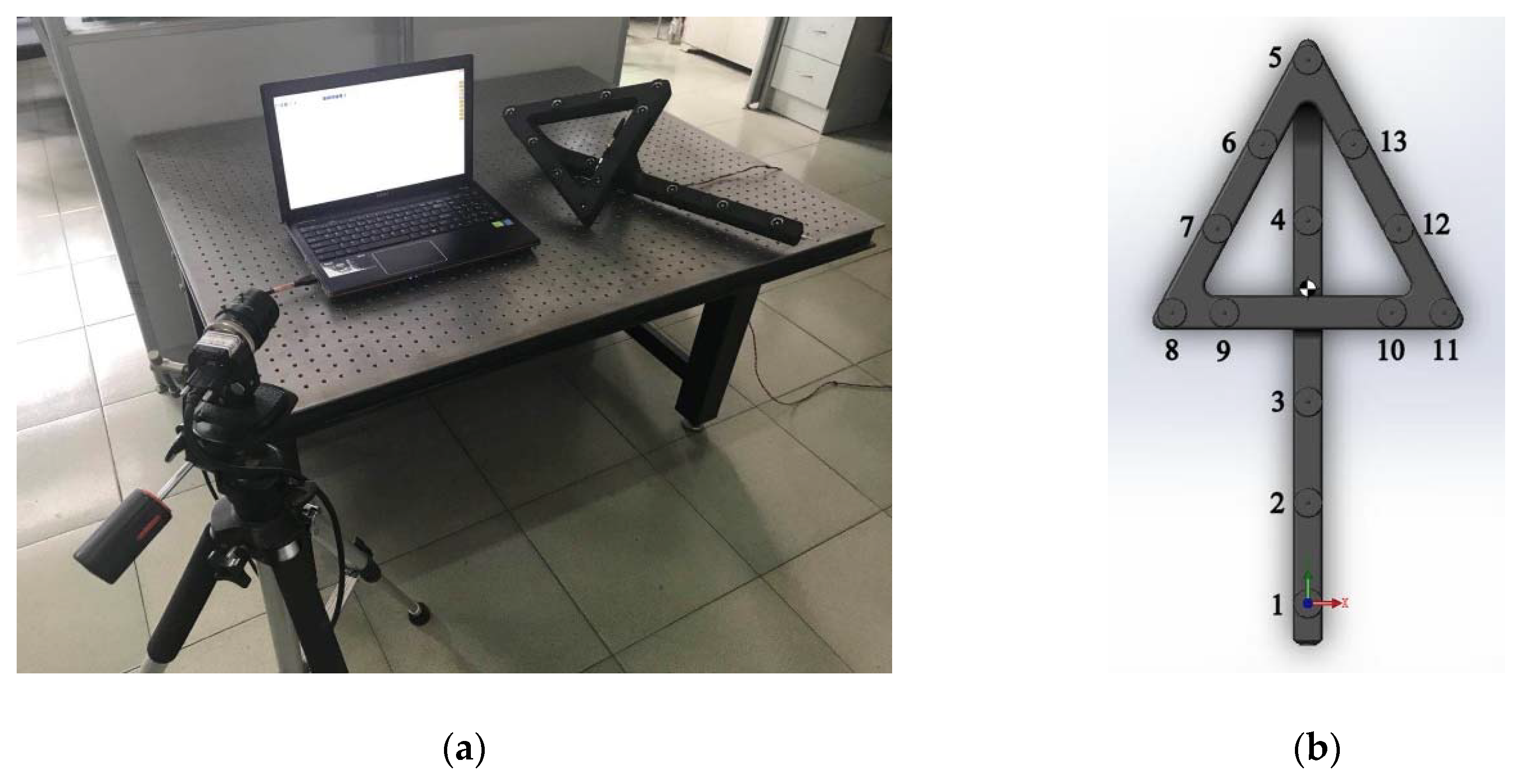
2. Brief Description of LPCMS
3. Control Point Position Calibration
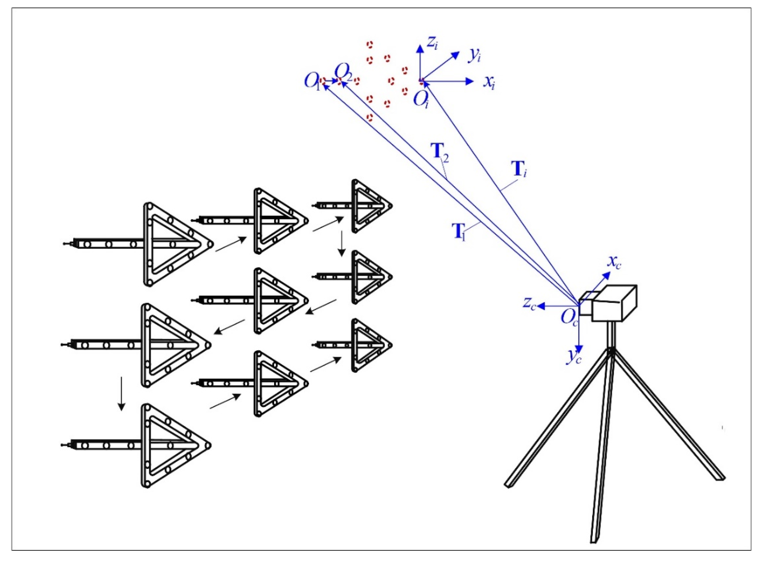
3.1. Calibration Procedure
3.2. Calibration Method Derivation
3.3. Algorithm Acceleration
3.4. Light Pen Coordinate System Establishement
- Determine the origin of . The first control point is used as the origin. Then a new set of translation vectors is calculated:
- Determine the z-axis of . The fifth to 13th control points are designed to be coplanar. Actually, they are not strictly coplanar because of the machining and installation error. Therefore, a plane is fitted using their new translation vectors . The direction of its unit normal vector, which can be denoted as , is used as the z-axis of .
- Determine the y-axis of . For the same reason, the first to fourth control points are not strictly collinear. They are projected to the plane fitted before. A line is fitted using the coordinates of their projections. The unit direction vector of this line is denoted as . Since the fitted line is in the plane, is satisfied. The direction of can be used as the y-axis of .
- Determining the x-axis of . Given the direction of y-axis and z-axis , the direction of x-axis, which is denoted as , can be determined by the cross product:
- Determining the relative positions of control points with coordinates in . With the origin and axes determined, the coordinates of control points in , which can be denoted as can be calculates as follows:
4. Experiment
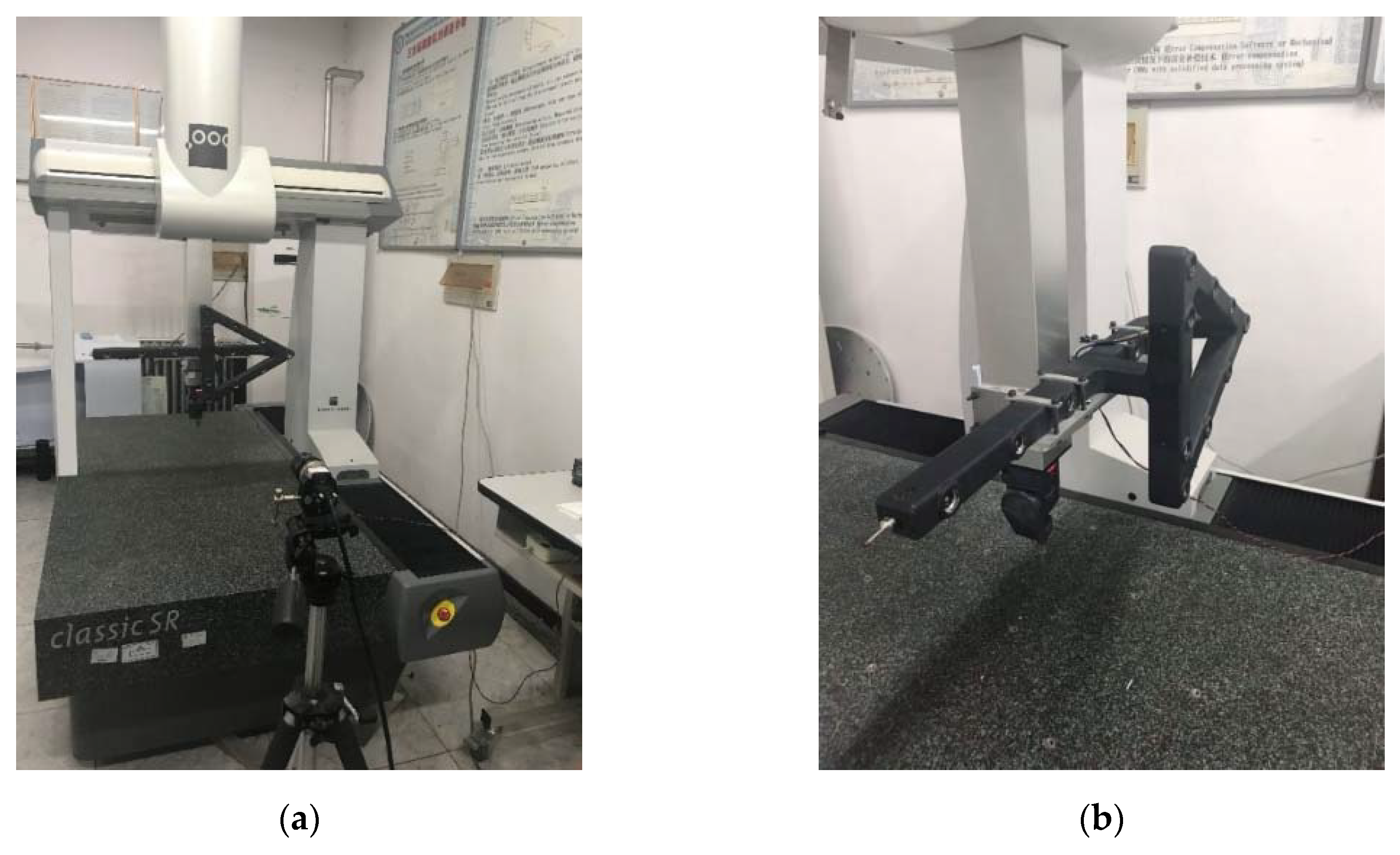
4.1. Actual Control Point Position Calibration Experiment
4.2. Simulation Experiment
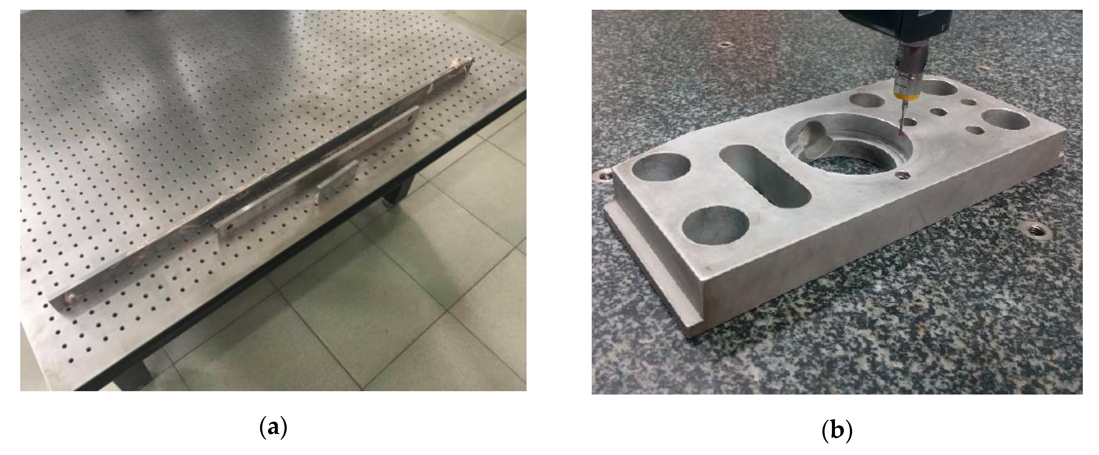
4.3. Measurement Experiment of LPCMS
5. Conclusions
Author Contributions
Funding
Conflicts of Interest
References
- Várady, T.; Martin, R.R.; Cox, J. Reverse engineering of geometric models—An introduction. Comput. Aided Des. 1997, 29, 255–268. [Google Scholar] [CrossRef]
- Brezina, I. Coordinate Measuring Machines and Systems. Measurement 1997, 20, 287. [Google Scholar] [CrossRef]
- Zhang, G.X. Coordinate Measuring Machines, 1st ed.; Tianjin University Press: Tainjin, China, 1999; pp. 18–27. [Google Scholar]
- Milroy, M.J.; Weir, D.J.; Bradley, D.C.; Vickers, G.W. Reverse engineering employing a 3D laser scanner: A case study. Int. J. Adv. Manuf. Technol. 1996, 12, 111–121. [Google Scholar] [CrossRef]
- Aguado, S.; Samper, D.; Santolaria, J.; Aguilar, J.J. Identification strategy of error parameter in volumetric error compensation of machine tool based on laser tracker measurements. Int. J. Mach. Tool. Manu. 2012, 53, 160–169. [Google Scholar] [CrossRef]
- Reich, C.; Ritter, R.; Thesing, J. 3-D shape measurement of complex objects by combining photogrammetry and fringe projection. Opt. Eng. 2000, 39, 224–231. [Google Scholar] [CrossRef]
- Liu, S.G.; Peng, K.; Huang, F.S.; Zhang, G.X.; Li, P. A porTable 3D vision coordinate measurement system using a light pen. Key Eng. Mater. 2005, 295, 331–336. [Google Scholar]
- Qin, D.H. Research on the Technology and System of Portable Light Pen Coordinate Measurement System. Ph.D. Thesis, Huazhong University of Science and Technology, Wuhan, China, 2009. [Google Scholar]
- Xie, Z.X.; Han, Z.H.; Gao, X. Key technologies of monocular vision measurement system with light pen. Chin. Opt. 2013, 6, 780–787. [Google Scholar]
- Liu, S.G.; Zhang, H.L.; Dong, Y.H.; Tang, S.L.; Jiang, Z.Z. Portable light pen 3D vision coordinate measuring system—Probe tip center calibration. Meas. Sci. Rev. 2013, 13, 194–199. [Google Scholar] [CrossRef]
- Fu, S.; Zhang, L.Y.; Ye, N.; Zhang, W.Z.; Liu, S.L. A flexible approach to light pen calibration for a monocular-vision-based coordinate measuring system. Meas. Sci. Technol. 2014, 25, 1–8. [Google Scholar] [CrossRef]
- Tsai, R. A versatile camera calibration technique for high-accuracy 3D machine vision metrology using off-the-shelf TV cameras and lenses. IEEE J. Robot. Autom. 1987, 3, 323–344. [Google Scholar] [CrossRef]
- Zhang, Z.Y. A flexible new technique for camera calibration. IEEE Trans. Pattern Anal. Mach. Intell. 2000, 22, 1330–1334. [Google Scholar] [CrossRef]
- Quan, L.; Lan, Z.D. Linear N-point camera pose determination. IEEE Trans. Pattern Anal. Mach. Intell. 1999, 21, 774–780. [Google Scholar] [CrossRef]
- Sezliski, R. Computer Vision: Algorithms and Applications, 1st ed.; Springer: New York, NY, USA, 2011; pp. 45–47. [Google Scholar]
- Lepetit, V.; Moreno-Noguer, F.; Fua, P. EPnP. An accurate O(n) solution to the PnP problem. Int. J. Comput. Vision. 2009, 81, 155–166. [Google Scholar] [CrossRef]
- Li, S.Q.; Xu, C.; Xie, M. A robust O(n) solution to the perspective-n-point problem. IEEE Trans. Pattern Anal. Mach. Intell. 2012, 34, 1444–1450. [Google Scholar] [CrossRef] [PubMed]
- Xu, D.; Li, Y.F.; Tan, M. A general recursive linear method and unique solution pattern design for the perspective-n-point problem. Image Vis. Comput. 2008, 26, 740–750. [Google Scholar] [CrossRef]
- Zhang, R.; Liu, S.G.; Wang, S.; Song, X.X. Stylus tip center position self-calibration based on invariable distances in light-pen systems. Sensors 2017, 17, 131. [Google Scholar] [CrossRef] [PubMed]
- Furukawa, Y.; Ponce, J. Accurate camera calibration from multi-view stereo and bundle adjustment. Int. J. Comput. Vis. 2008, 84, 257–268. [Google Scholar]
- Hartley, R.I.; Zisserman, A. Multiple View Geometry in Computer Vision, 2nd ed.; Cambridge University Press: New York, NY, USA, 2003; pp. 434–456. [Google Scholar]
- Nocedal, J.; Wright, S.J. Numerical Optimization, 2nd ed.; Springer: New York, NY, USA, 2006; pp. 270–302. [Google Scholar]
- Agarwal, S.; Snavely, N.; Seitz, S.M.; Szeliski, R. Bundle Adjustment in the Large. In Proceedings of the European Conference on Computer Vision, Part II, Heraklion, Crete, Greece, 5–11 September 2010; pp. 29–42. [Google Scholar]
- Jeong, Y. Pushing the envelope of modern methods for bundle adjustment. IEEE Trans. Pattern Anal. Mach. Intell. 2012, 34, 1605–1617. [Google Scholar] [PubMed]


| Calibration Method | Advantages | Disadvantages |
|---|---|---|
| Direct Measurement Method in [10] | Fast calibration speed; Easy operation; No need of calculation | Unable to locate luminous center; Low accuracy |
| Structure from Motion Method in [11] | No need of extra equipment; High flexibility; Able to calibrate in real-time | Complicated calculation; Low reliability |
| The Proposed Method | High accuracy; Simple calculation process; Able to process tremendous data | High time consumption; Complex calibration procedure |
| Control Point Index | |||
|---|---|---|---|
| 1 | −31.343 | −319.578 | 1542.853 |
| 2 | −130.327 | −317.944 | 1544.784 |
| 3 | −230.340 | −316.726 | 1546.672 |
| 4 | −410.261 | −314.924 | 1550.004 |
| 5 | −571.145 | −309.694 | 1452.690 |
| 6 | −486.863 | −266.087 | 1451.879 |
| 7 | −402.882 | −222.740 | 1451.028 |
| 8 | −318.265 | −179.508 | 1450.131 |
| 9 | −319.429 | −234.657 | 1449.130 |
| 10 | −322.394 | −394.058 | 1447.287 |
| 11 | −323.049 | −449.060 | 1446.452 |
| 12 | −405.913 | −402.371 | 1448.562 |
| 13 | −488.814 | −355.599 | 1450.688 |
| Control Point Index | |||
|---|---|---|---|
| 1 | 0.000 | 0.000 | 0.000 |
| 2 | −0.228 | 99.159 | −0.064 |
| 3 | −0.025 | 199.053 | −0.071 |
| 4 | 0.730 | 379.013 | −0.024 |
| 5 | −0.874 | 538.094 | 100.333 |
| 6 | −45.681 | 454.440 | 100.167 |
| 7 | −90.222 | 371.082 | 100.043 |
| 8 | −134.657 | 287.086 | 99.951 |
| 9 | −79.488 | 287.447 | 100.223 |
| 10 | 79.949 | 288.113 | 99.950 |
| 11 | 134.962 | 287.970 | 100.048 |
| 12 | 89.451 | 371.514 | 100.119 |
| 13 | 43.858 | 455.096 | 100.176 |
| Calibration Index | 1–4 1 | 1–5 | 5–8 | 5–11 | 8–11 | 1–8 | 1–11 |
|---|---|---|---|---|---|---|---|
| 1 | 379.014 | 547.369 | 284.435 | 284.629 | 269.620 | 332.471 | 333.393 |
| 2 | 379.022 | 547.385 | 284.446 | 284.611 | 269.599 | 332.476 | 333.425 |
| 3 | 379.012 | 547.355 | 284.461 | 284.603 | 269.625 | 332.483 | 333.420 |
| 4 | 379.030 | 547.344 | 284.447 | 284.622 | 269.615 | 332.450 | 333.409 |
| 5 | 379.005 | 547.363 | 284.452 | 284.631 | 269.603 | 332.456 | 333.396 |
| 6 | 379.024 | 547.359 | 284.458 | 284.615 | 269.621 | 332.464 | 333.433 |
| 7 | 379.019 | 547.388 | 284.432 | 284.623 | 269.608 | 332.469 | 333.401 |
| 8 | 379.008 | 547.354 | 284.441 | 284.618 | 269.619 | 332.472 | 333.422 |
| 9 | 379.027 | 547.376 | 284.459 | 284.607 | 269.618 | 332.456 | 333.411 |
| 10 | 379.016 | 547.371 | 284.429 | 284.614 | 269.603 | 332.448 | 333.430 |
| Ave | 379.018 | 547.366 | 284.446 | 284.617 | 269.613 | 332.465 | 333.414 |
| Std | 0.00818 | 0.01408 | 0.01158 | 0.00911 | 0.00909 | 0.01165 | 0.01417 |
| Range | 0.025 | 0.044 | 0.032 | 0.028 | 0.026 | 0.035 | 0.040 |
| Distance | 100 Gauge | 250 Gauge | 1000 Gauge | Cylinder | ||||
|---|---|---|---|---|---|---|---|---|
| Ave | Std | Ave | Std | Ave | Std | Ave | Std | |
| 2 m | 99.994 | 0.0025 | 250.009 | 0.0028 | 999.982 | 0.0062 | 63.502 | 0.0022 |
| 4 m | 100.002 | 0.0037 | 250.014 | 0.0049 | 999.994 | 0.0133 | 63.507 | 0.0027 |
| 6 m | 100.006 | 0.0048 | 249.983 | 0.0072 | 1000.015 | 0.0187 | 63.513 | 0.0042 |
| 8 m | 99.988 | 0.0056 | 250.003 | 0.0123 | 999.989 | 0.0227 | 63.505 | 0.0053 |
| 10 m | 99.992 | 0.0071 | 250.007 | 0.0158 | 999.979 | 0.0315 | 63.519 | 0.0085 |
| Distance | Method in [10] | Method in [11] | Proposed Method | |||
|---|---|---|---|---|---|---|
| Ave | Std | Ave | Std | Ave | Std | |
| 2 m | 250.033 | 0.0258 | 250.019 | 0.0121 | 250.009 | 0.0028 |
| 4 m | 249.976 | 0.0376 | 250.033 | 0.0213 | 250.014 | 0.0049 |
| 6 m | 249.982 | 0.0627 | 249.975 | 0.0381 | 249.983 | 0.0072 |
| 8 m | 250.041 | 0.1032 | 250.029 | 0.0419 | 250.003 | 0.0123 |
| 10 m | 249.963 | 0.1523 | 250.038 | 0.0688 | 250.007 | 0.0158 |
© 2020 by the authors. Licensee MDPI, Basel, Switzerland. This article is an open access article distributed under the terms and conditions of the Creative Commons Attribution (CC BY) license (http://creativecommons.org/licenses/by/4.0/).
Share and Cite
Wang, S.; Liu, S.; Mao, Q. A CMM-Based Method of Control Point Position Calibration for Light Pen Coordinate Measuring System. Sensors 2020, 20, 5592. https://doi.org/10.3390/s20195592
Wang S, Liu S, Mao Q. A CMM-Based Method of Control Point Position Calibration for Light Pen Coordinate Measuring System. Sensors. 2020; 20(19):5592. https://doi.org/10.3390/s20195592
Chicago/Turabian StyleWang, Sen, Shugui Liu, and Qing Mao. 2020. "A CMM-Based Method of Control Point Position Calibration for Light Pen Coordinate Measuring System" Sensors 20, no. 19: 5592. https://doi.org/10.3390/s20195592
APA StyleWang, S., Liu, S., & Mao, Q. (2020). A CMM-Based Method of Control Point Position Calibration for Light Pen Coordinate Measuring System. Sensors, 20(19), 5592. https://doi.org/10.3390/s20195592


