Application of FRAME for Simultaneous LIF and LII Imaging in Sooting Flames Using a Single Camera

 , , , , and
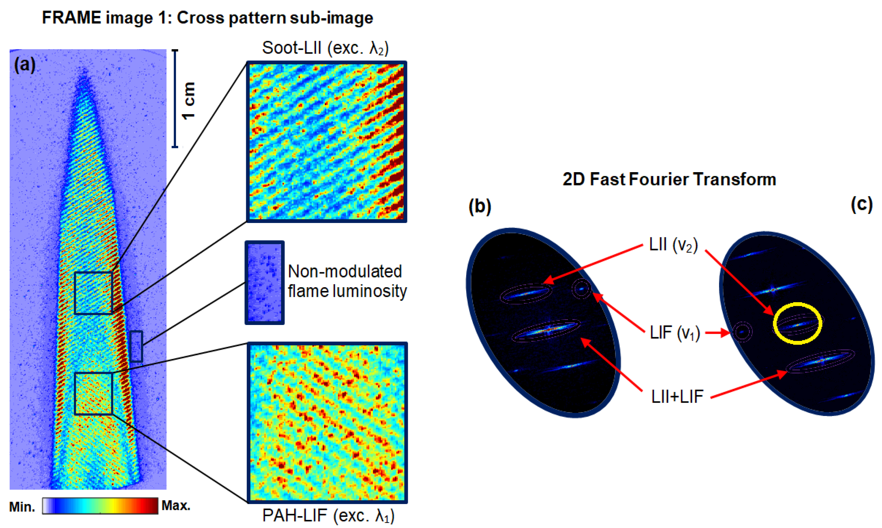
Abstract
1. Introduction
2. Frequency Recognition Algorithm for Multiple Exposures (FRAME)
3. Description of the Experiment
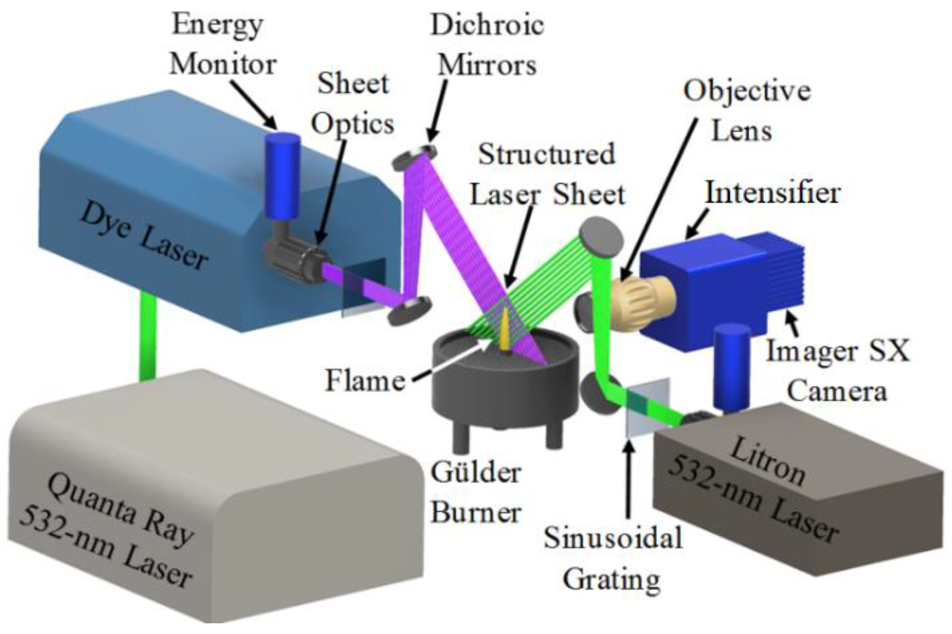
3.1. FRAME Optical Setup
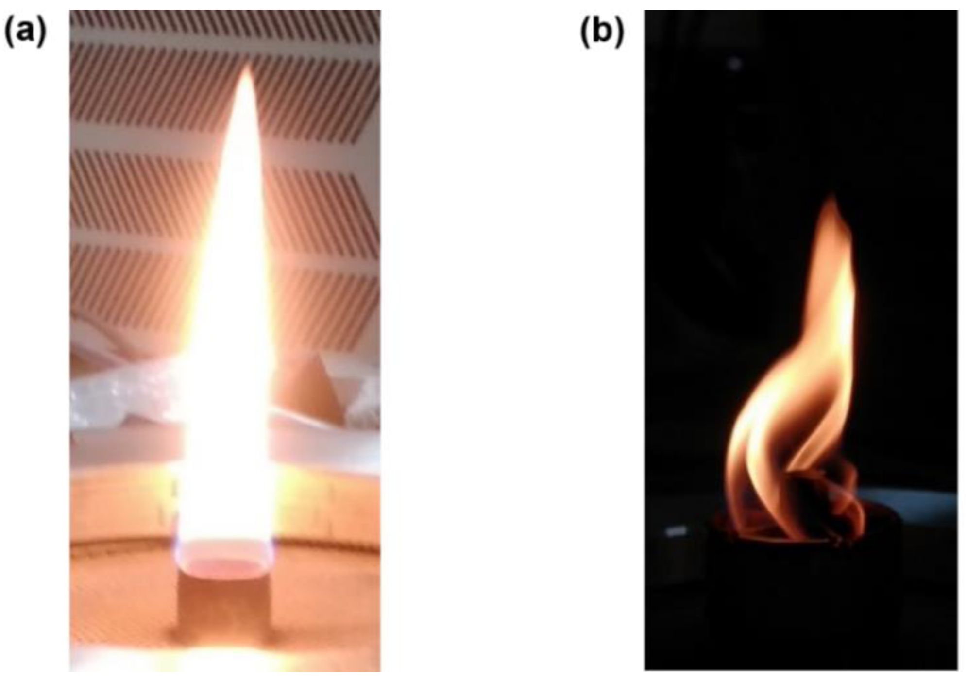
3.2. Details of the Burner and Flames
4. Results
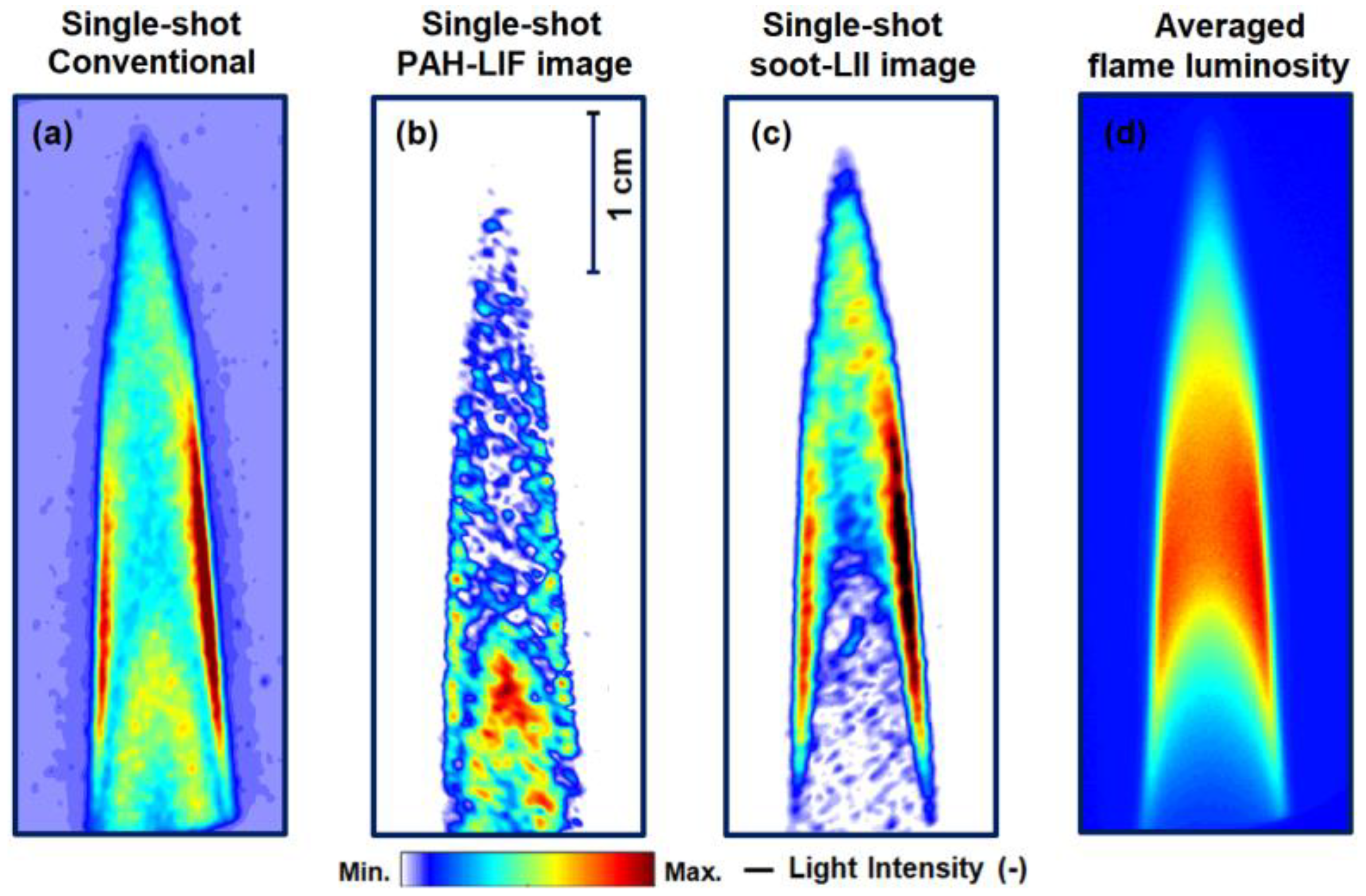
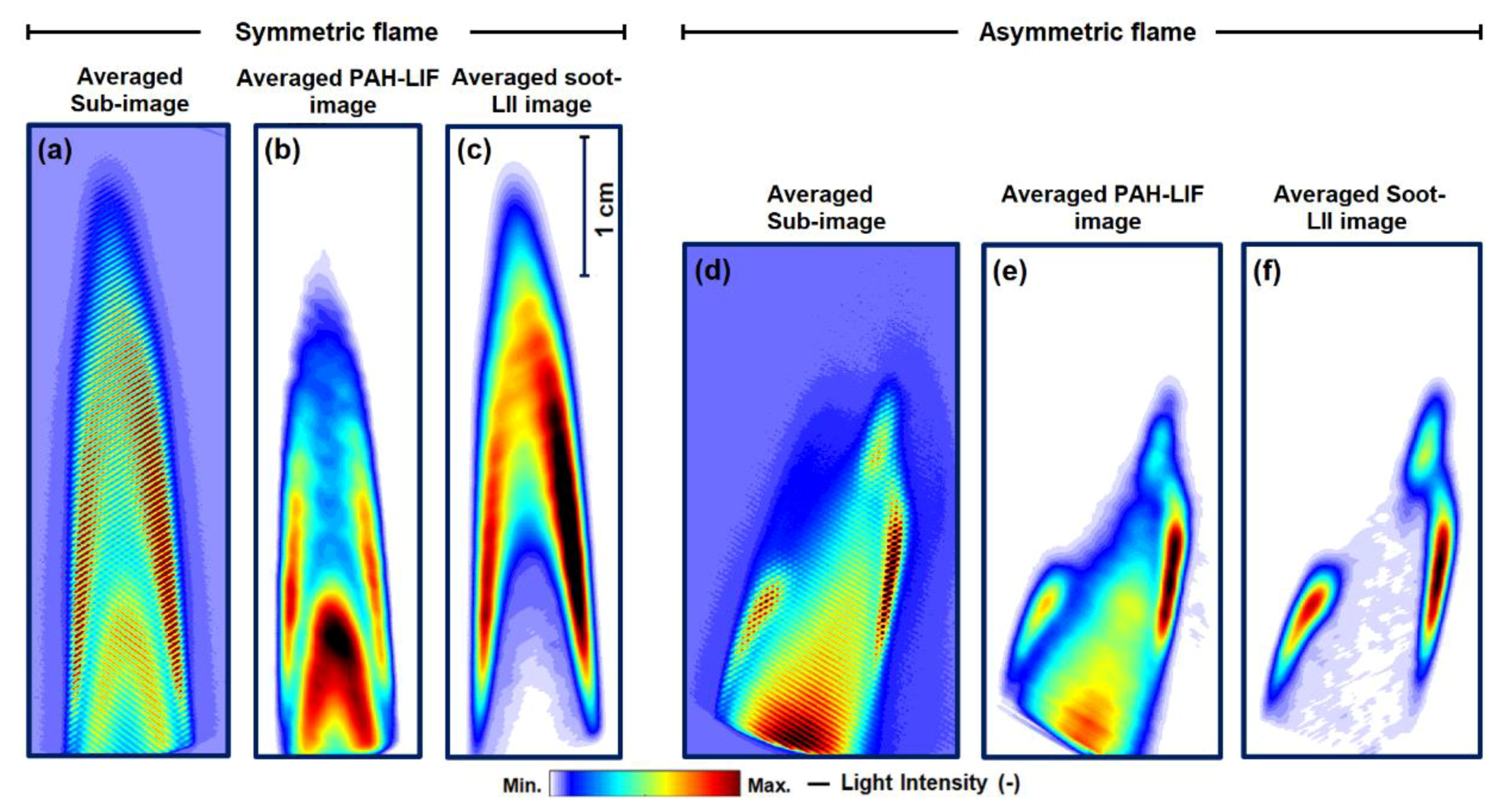
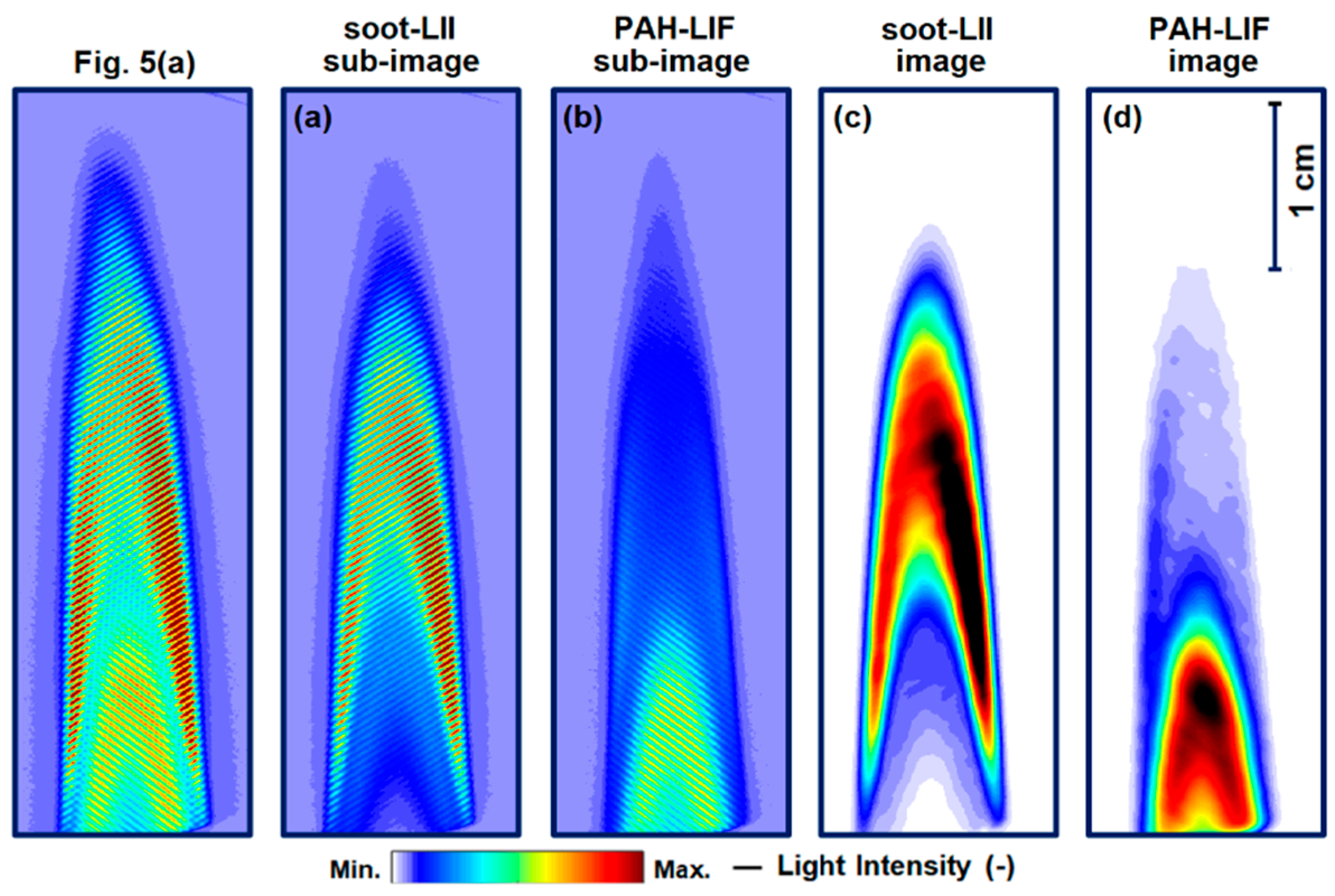
4.1. Simultaneous PAH-LIF and Soot-LII Imaging
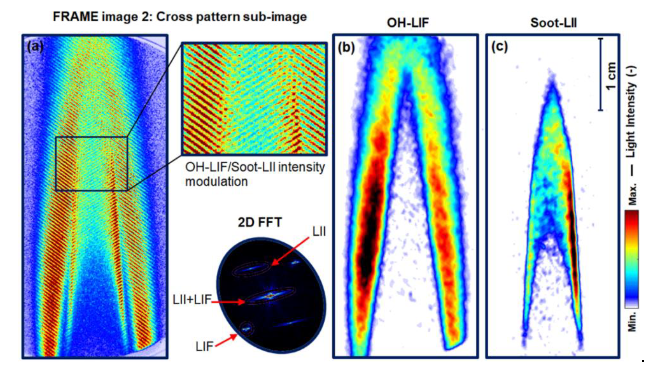
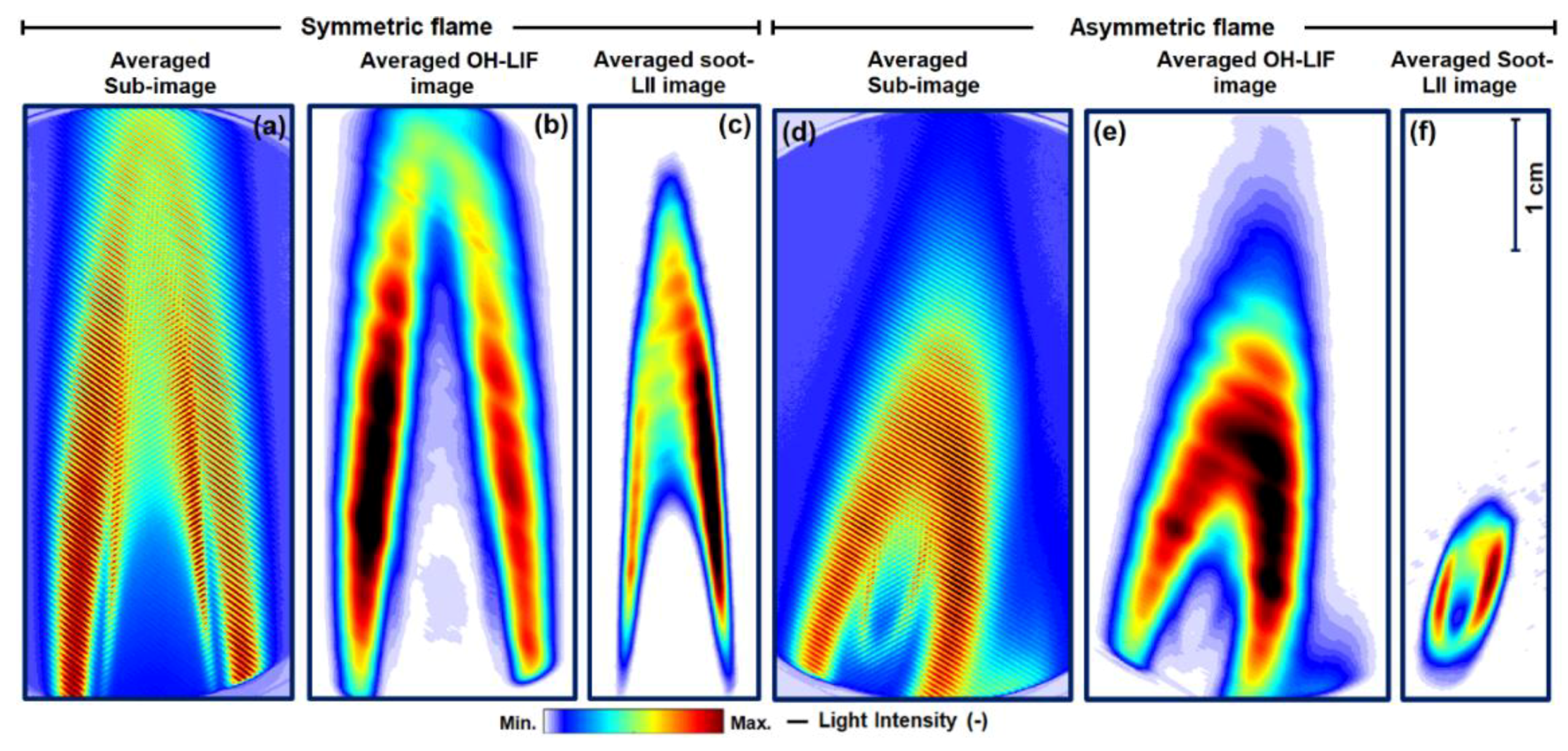
4.2. Simultaneous OH-LIF and Soot-LII Imaging
5. Conclusions
Author Contributions
Funding
Acknowledgments
Conflicts of Interest
Appendix A

References
- Glassman, I.; Yetter, R.A. Combustion, 4th ed.; Academic Press: Cambridge, MA, USA, 2008. [Google Scholar] [CrossRef]
- Eckbreth, A.C. Laser Diagnostics for Combustion Temperature and Species; Abacus: New York, NY, USA, 1988. [Google Scholar]
- Kohse-Höinghaus, K.; Barlow, R.S.; Aldén, M.; Wolfrum, J. Combustion at the focus: Laser diagnostics and control. Proc. Combust. Inst. 2005, 30, 89–123. [Google Scholar] [CrossRef]
- Paul, P.H.; Najm, H.N. Planar laser-induced fluorescence imaging of flame heat release rate. Symp. Int. Combust. 1998, 27, 43–50. [Google Scholar] [CrossRef]
- Miller, J.D.; Slipchenko, M.; Meyer, T.R.; Jiang, N.; Lempert, W.R.; Gord, J.R. Ultrahigh-frame-rate OH fluorescence imaging in turbulent flames using a burst-mode optical parametric oscillator. Opt. Lett. 2009, 34, 1309–1311. [Google Scholar] [CrossRef]
- Liu, H.; Geng, C.; Yang, Z.; Cui, Y.; Yao, M. Effect of Wall Temperature on Acetylene Diffusion Flame–Wall Interaction Based on Optical Diagnostics and CFD Simulation. Energies 2018, 11, 1264. [Google Scholar] [CrossRef]
- Retzer, U.; Pan, R.; Werblinski, T.; Huber, F.J.T.; Slipchenko, M.N.; Meyer, T.R.; Zigan, L.; Will, S. Burst-mode OH/CH2O planar laser-induced fluorescence imaging of the heat release zone in an unsteady flame. Opt. Express 2018, 26, 18105–18114. [Google Scholar] [CrossRef] [PubMed]
- Röder, M.; Dreier, T.; Schulz, C. Simultaneous measurement of localized heat-release with OH/CH2O–LIF imaging and spatially integrated OH* chemiluminescence in turbulent swirl flames. Proc. Combust. Inst. 2013, 34, 3549–3556. [Google Scholar] [CrossRef]
- Service, R.F. Study Fingers Soot as a Major Player in Global Warming. Science 2008, 319, 1745. [Google Scholar] [CrossRef]
- Karataş, A.E.; Gülder, Ö.L. Soot formation in high pressure laminar diffusion flames. Prog. Energy Combust. Sci. 2012, 38, 818–845. [Google Scholar] [CrossRef]
- Desgroux, P.; Mercier, X.; Thomson, K.A. Study of the formation of soot and its precursors in flames using optical diagnostics. Proc. Combust. Inst. 2013, 34, 1713–1738. [Google Scholar] [CrossRef]
- Yamamoto, K.; Takemoto, M. Reductions of PAH and Soot by Center Air Injection. Environments 2014, 1, 42. [Google Scholar] [CrossRef]
- Garcés, H.O.; Fuentes, A.; Reszka, P.; Carvajal, G. Analysis of Soot Propensity in Combustion Processes Using Optical Sensors and Video Magnification. Sensors 2018, 18, 1514. [Google Scholar] [CrossRef] [PubMed]
- Vander Wal, R.L.; Jensen, K.A.; Choi, M.Y. Simultaneous laser-induced emission of soot and polycyclic aromatic hydrocarbons within a gas-jet diffusion flame. Combust. Flame 1997, 109, 399–414. [Google Scholar] [CrossRef]
- Michelsen, H.A.; Schulz, C.; Smallwood, G.J.; Will, S. Laser-induced incandescence: Particulate diagnostics for combustion, atmospheric, and industrial applications. Prog. Energy Combust. Sci. 2015, 51, 2–48. [Google Scholar] [CrossRef]
- Hanson, R.K. Combustion diagnostics: Planar imaging techniques. Symp. Int. Combust. 1988, 21, 1677–1691. [Google Scholar] [CrossRef]
- Aldén, M.; Bood, J.; Li, Z.; Richter, M. Visualization and understanding of combustion processes using spatially and temporally resolved laser diagnostic techniques. Proc. Combust. Inst. 2011, 33, 69–97. [Google Scholar] [CrossRef]
- Chan, C.; Daily, J.W. Measurement of temperature in flames using laser induced fluorescence spectroscopy of OH. Appl. Opt. 1980, 19, 1963–1968. [Google Scholar] [CrossRef]
- Chan, C.; Daily, J.W. Laser excitation dynamics of OH in flames. Appl. Opt. 1980, 19, 1357–1367. [Google Scholar] [CrossRef]
- Schulz, C.; Kock, B.F.; Hofmann, M.; Michelsen, H.; Will, S.; Bougie, B.; Suntz, R.; Smallwood, G. Laser-induced incandescence: Recent trends and current questions. Appl. Phys. B 2006, 83, 333. [Google Scholar] [CrossRef]
- Sjöholm, J.; Rosell, J.; Li, B.; Richter, M.; Li, Z.; Bai, X.-S.; Aldén, M. Simultaneous visualization of OH, CH, CH2O and toluene PLIF in a methane jet flame with varying degrees of turbulence. Proc. Combust. Inst. 2013, 34, 1475–1482. [Google Scholar] [CrossRef]
- Zhou, B.; Brackmann, C.; Li, Z.; Aldén, M.; Bai, X.-S. Simultaneous multi-species and temperature visualization of premixed flames in the distributed reaction zone regime. Proc. Combust. Inst. 2015, 35, 1409–1416. [Google Scholar] [CrossRef]
- Franzelli, B.; Scouflaire, P.; Candel, S. Time-resolved spatial patterns and interactions of soot, PAH and OH in a turbulent diffusion flame. Proc. Combust. Inst. 2015, 35, 1921–1929. [Google Scholar] [CrossRef]
- Mulla, I.A.; Renou, B. Simultaneous imaging of soot volume fraction, PAH, and OH in a turbulent n-heptane spray flame. Combust. Flame 2019, 209, 452–466. [Google Scholar] [CrossRef]
- Fassel, V.A.; Katzenberger, J.M.; Winge, R.K. Effectiveness of Interference Filters for Reduction of Stray Light Effects in Atomic Emission Spectrometry. Appl. Spectrosc. 1979, 33, 1–5. [Google Scholar] [CrossRef]
- Kempema, N.J.; Long, M.B. Quantitative Rayleigh thermometry for high background scattering applications with structured laser illumination planar imaging. Appl. Opt. 2014, 53, 6688–6697. [Google Scholar] [CrossRef] [PubMed]
- Kristensson, E.; Ehn, A.; Bood, J.; Aldén, M. Advancements in Rayleigh scattering thermometry by means of structured illumination. Proc. Combust. Inst. 2015, 35, 3689–3696. [Google Scholar] [CrossRef]
- Berrocal, E.; Kristensson, E.; Richter, M.; Linne, M.; Aldén, M. Application of structured illumination for multiple scattering suppression in planar laser imaging of dense sprays. Opt. Express 2008, 16, 17870–17881. [Google Scholar] [CrossRef]
- Mishra, Y.N. Droplet Size, Concentration, and Temperature Mapping in Sprays Using SLIPI-Based Techniques; Lund University: Scandinavia, Sweden, 2018. [Google Scholar]
- Kulkarni, A.P.; Deshmukh, D. Planar liquid volume fraction measurements in air-blast sprays using SLIPI technique with numerical corrections. Appl. Phys. B 2018, 124, 187. [Google Scholar] [CrossRef]
- Berrocal, E.; Kristensson, E.; Hottenbach, P.; Aldén, M.; Grünefeld, G. Quantitative imaging of a non-combusting diesel spray using structured laser illumination planar imaging. Appl. Phys. B 2012, 109, 683–694. [Google Scholar] [CrossRef]
- Mishra, Y.N.; Kristensson, E.; Koegl, M.; Jönsson, J.; Zigan, L.; Berrocal, E. Comparison between two-phase and one-phase SLIPI for instantaneous imaging of transient sprays. Exp. Fluids 2017, 58, 110. [Google Scholar] [CrossRef]
- Li, Z.; Borggren, J.; Berrocal, E.; Ehn, A.; Aldén, M.; Richter, M.; Kristensson, E. Simultaneous multispectral imaging of flame species using Frequency Recognition Algorithm for Multiple Exposures (FRAME). Combust. Flame 2018, 192, 160–169. [Google Scholar] [CrossRef]
- Dorozynska, K.; Kristensson, E. Implementation of a multiplexed structured illumination method to achieve snapshot multispectral imaging. Opt. Express 2017, 25, 17211–17226. [Google Scholar] [CrossRef] [PubMed]
- Snelling, D.R.; Thomson, K.A.; Smallwood, G.J.; Gülder, Ö.L. Two-dimensional imaging of soot volume fraction in laminar diffusion flames. Appl. Opt. 1999, 38, 2478–2485. [Google Scholar] [CrossRef] [PubMed]
- Thomson, K.A.; Gülder, Ö.L.; Weckman, E.J.; Fraser, R.A.; Smallwood, G.J.; Snelling, D.R. Soot concentration and temperature measurements in co-annular, nonpremixed CH4/air laminar flames at pressures up to 4 MPa. Combust. Flame 2005, 140, 222–232. [Google Scholar] [CrossRef]
- Joo, H.I.; Gülder, Ö.L. Soot formation and temperature field structure in co-flow laminar methane–air diffusion flames at pressures from 10 to 60atm. Proc. Combust. Inst. 2009, 32, 769–775. [Google Scholar] [CrossRef]
- Zheng, S.; Qi, C.; Zhou, H. Experimental investigations of temperature distribution in non-premixed flames with different gas compositions by large lateral shearing interferometry. J. Quant. Spectrosc. Radiat. Transf. 2019, 224, 445–452. [Google Scholar] [CrossRef]
- Kristensson, E.; Bood, J.; Aldén, M.; Nordström, E.; Zhu, J.; Huldt, S.; Bengtsson, P.-E.; Nilsson, H.; Berrocal, E.; Ehn, A. Stray light suppression in spectroscopy using periodic shadowing. Opt. Express 2014, 22, 7711–7721. [Google Scholar] [CrossRef]
- He, S.; Deng, X.; Lahann, J.; Hess, H. A Two-Dimensional Lock-In Algorithm for Signal Analysis in Patterned Images. IEEE Trans. Biomed. Eng. 2016, 63, 2436–2440. [Google Scholar] [CrossRef]
- Kristensson, E.; Li, Z.; Berrocal, E.; Richter, M.; Aldén, M. Instantaneous 3D imaging of flame species using coded laser illumination. Proc. Combust. Inst. 2016, 36, 3313–4618. [Google Scholar] [CrossRef]
- Tian, B.; Gao, Y.; Balusamy, S.; Hochgreb, S. High spatial resolution laser cavity extinction and laser-induced incandescence in low-soot-producing flames. Appl. Phys. B 2015, 120, 469–487. [Google Scholar] [CrossRef]
- Michelsen, H.A. Probing soot formation, chemical and physical evolution, and oxidation: A review of in situ diagnostic techniques and needs. Proc. Combust. Inst. 2017, 36, 717–735. [Google Scholar] [CrossRef]
- Smooke, M.D.; Long, M.B.; Connelly, B.C.; Colket, M.B.; Hall, R.J. Soot formation in laminar diffusion flames. Combust. Flame 2005, 143, 613–628. [Google Scholar] [CrossRef]
- Jerez, A.; Cruz Villanueva, J.J.; Figueira da Silva, L.F.; Demarco, R.; Fuentes, A. Measurements and modeling of PAH soot precursors in coflow ethylene/air laminar diffusion flames. Fuel 2019, 236, 452–460. [Google Scholar] [CrossRef]


© 2020 by the authors. Licensee MDPI, Basel, Switzerland. This article is an open access article distributed under the terms and conditions of the Creative Commons Attribution (CC BY) license (http://creativecommons.org/licenses/by/4.0/).
Share and Cite
Mishra, Y.N.; Boggavarapu, P.; Chorey, D.; Zigan, L.; Will, S.; Deshmukh, D.; Rayavarapu, R. Application of FRAME for Simultaneous LIF and LII Imaging in Sooting Flames Using a Single Camera. Sensors 2020, 20, 5534. https://doi.org/10.3390/s20195534
Mishra YN, Boggavarapu P, Chorey D, Zigan L, Will S, Deshmukh D, Rayavarapu R. Application of FRAME for Simultaneous LIF and LII Imaging in Sooting Flames Using a Single Camera. Sensors. 2020; 20(19):5534. https://doi.org/10.3390/s20195534
Chicago/Turabian StyleMishra, Yogeshwar Nath, Prasad Boggavarapu, Devashish Chorey, Lars Zigan, Stefan Will, Devendra Deshmukh, and Ravikrishna Rayavarapu. 2020. "Application of FRAME for Simultaneous LIF and LII Imaging in Sooting Flames Using a Single Camera" Sensors 20, no. 19: 5534. https://doi.org/10.3390/s20195534
APA StyleMishra, Y. N., Boggavarapu, P., Chorey, D., Zigan, L., Will, S., Deshmukh, D., & Rayavarapu, R. (2020). Application of FRAME for Simultaneous LIF and LII Imaging in Sooting Flames Using a Single Camera. Sensors, 20(19), 5534. https://doi.org/10.3390/s20195534