Abstract
This article presents a dual-polarized, high gain multi-beam and high T/Rx channel-to-channel isolation antenna module for 24 GHz sensor applications. The proposed antenna is configured to support 2-Tx and 2-Rx channels with a pair of vertically polarized (VP) radiation pattern and a pair of horizontally polarized (HP) radiation pattern. Further, each linearly polarized T/Rx antenna is configured by 2 × 4 array with a multi-layer integrated feed network, resulting in four sets of 2 × 4 array antennas fabricated within a single printed circuit board (PCB). Since multiple RF channels must be ensured with minimal interference, high antenna-to-antenna, including Tx-to-Tx, Rx-to-Rx, and Tx-to-Rx port isolations in the proposed antenna are achieved by multi-layered feed network and four sets of T-shaped magnetic walls. To verify the performance of the proposed structure, a 2-Tx and 2-Rx antenna module was fabricated at 24 GHz. The fabricated antenna showed a measured maximum 10-dB impedance bandwidth of 3.9% with a maximum measured gain of 11.7 dBi, considering both Tx and Rx. Further, the measured channel-to-channel isolations were always better than 35.6 dB at 24 GHz.
1. Introduction
Sensors have become the key enabling technologies of the Internet-of-Things (IoT) applications such as manufacturing and industrial support [1,2,3,4,5], transportation and mobility [1,2,3,4,5,6], energy [7,8], retail [9,10,11], smart cities [12,13], health care [14,15], supply chain [16,17,18], agriculture [19,20], and buildings [21,22,23]. With these growing demand for contactless and wireless data acquisition and services, the demand for optimized sensors in various fields is also growing. To further extend the IoT potentials, recent research has focused on enhancing the data collection and analysis capabilities, and flexible sensor configuration within the IoT platform. Although the IoT sensor hierarchy includes many different levels such as raw data collection and analysis [24,25,26,27,28,29], motion detection [30,31,32], object analysis [33,34,35], activity monitoring [36,37,38,39], and context computation [40,41,42,43,44], the physical level of gathering raw data must be of primary concern. That is, as a massive number of wireless sensors carrying a massive amount of data at different frequencies, the antenna technologies capturing the required data at the desired frequencies must be ensured. Owing to increased sensor connectivity among multiple devices, an unavoidable level of microwave interference exists and thus potentially causes a significant degradation in the sensors’ performance [45,46,47,48]. To avoid performance degradation, the use of antennas with polarization diversity is considered to be one of the promising techniques to facilitate multiple microwave sensor operation with a reliable interference rejection [49,50,51,52,53]. There are typically four types of antenna polarizations, such as horizontal polarization (HP), vertical polarization (VP), right-hand circular polarization (RHCP), and left-hand polarization (LHCP). The best hardware configuration can be the support for all polarization types, but two polarization types can still be effective regarding circuit complexity, ease of integration, and cost for reconfigurable polarization RF-chain. Figure 1 shows the conceptual diagram for multi-channel radars with and without having polarization diversity. Typically, a radar sensor is capable of acquiring data such as target speed, target distance, and target location, whereas a multi-channel radar sensor must capture multiple target information simultaneously. As an example, Figure 1a shows multiple object identification or detection with a single polarization. Here, the multi-channel radar detects various information by simultaneously transmitting and receiving signals for different objects within the sensing coverage. However, each signal is easily corrupted by the interferences from neighboring objects reflecting multiple signals with the same kind of polarization, resulting in the collection of inaccurate raw data. On the other hand, if the multi-channel radar can transmit and receive signals through different polarizations, as shown in Figure 1b, the spectral channels can be isolated according to their polarization types, since a VP channel only responds with VP and vice versa. Thus, an accurate and reliable capturing of multiple raw data can be collected for multiple targets.
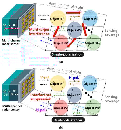
Figure 1.
Multi-channel radar sensors (a) without having polarization diversity and (b) with a dual-polarization by VP and HP for interference suppression.
To provide polarization diversity at high frequencies, multiple antennas with different types of fixed polarizations can be effectively used due to the physically reduced antenna size [54,55,56,57,58]. However, these reported antennas require an extra artificial magnetic conductor (AMC) layer, impractical patch, or feed geometry that makes them unsuitable as high-frequency applications. More importantly, insufficient isolation characteristics are obtained. Further, array architectures are required to increase antenna directivity and sensing distance. Especially for multi-channel radar sensors, the channel-to-channel isolation, including both antenna array and feed network, must be high to avoid the strong transmitter (Tx) signals directly leaking or coupling to the receiver (Rx) chain, resulting in a poor signal-to-noise ratio (SNR) and degradation in sensing performance. Although the polarization diversity antennas are physically separated, multiple antenna arrays, including feed networks, are fabricated within the same printed circuit board (PCB) to form a single sensor module. Thus, although the electromagnetic radiation patterns for Tx and Rx are highly isolated, the conduction path isolation among each array corresponding to each channel cannot be sufficiently ensured. Although there has been previous research to ensure multi-channel isolation based on a dielectric slab [59], slotted-ground [60], SIW cavity [61], antenna spacing adjustment [62], SIW slot [63], and waveguide SIW [64], they suffer from either insufficient isolation, bulky cavity, or feed geometry, or incapability of simultaneous TRX operation. Therefore, in this article, a dual-polarized antenna module with high antenna gain and high channel-to-channel isolation is presented. The presented antenna module uses 24 GHz to operate in industrial, scientific, and medical (ISM) band, which is available without any restriction. Further, multiple antenna arrays with a reasonable size can be made in this band.
2. Proposed Antenna Design
Figure 2 shows the detailed description of the proposed antenna structure with the front and side views as well as the detailed design parameters related to guide-rings. Each patch element is matched at 100 Ω and thus T-junction feed network with an impedance transformer is used.
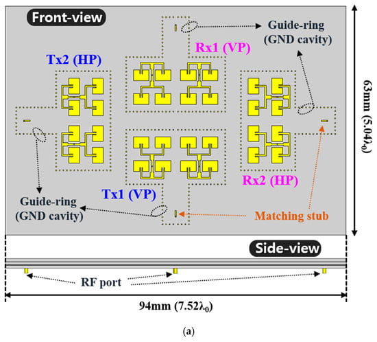
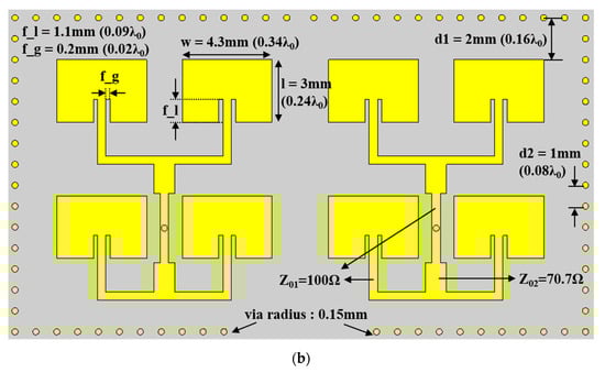
Figure 2.
Proposed 2-Tx and 2-Rx radar sensor antenna module with dual-polarization: (a) overview and (b) detailed design parameters for one array with a guide-ring.
The proposed antenna module was designed for a 2-Tx and 2-Rx radar sensor application with a pair of HP radiation and a pair of VP radiation patterns. Further, each antenna was identical and configured by a 2 × 4 array with an integrated feed network, a feed matching stub, and a guide-ring providing ground cavity for high antenna-to-antenna isolation. Since each antenna was used to transmit or receive an RF signal regarded as a channel information, high isolation among each antenna ensures high channel-to-channel isolation in a radar sensor platform. Figure 3 shows the multi-layer structure of the proposed antenna module, where 4-layer PCB was used. Here, the RF-35 Taconic substrate had a relative permittivity of 3.5 and loss tangent of 0.0018, whereas RO4450B was used as a prepreg. The radiation patch arrays and impedance matching stub for the feed network were designed on the upper layer. The second and third inner layers were used for the feed network and ground plane for the antenna elements. The bottom layer was used for the ground plane and RF ports. Further, a guide-ring for each array was implemented through the whole layers. That is, the proposed antenna structure adopted four guide-rings configured by multiple ground vias for each antenna array, including the feed network.
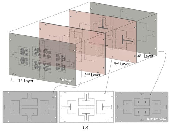
Figure 3.
Proposed antenna configuration with the (a) multi-layer information and (b) detailed views for each layer.
Although the neighboring antennas can be isolated by polarization diversity, the four arrays within a single antenna module shared a relatively large common ground plane, resulting in a field distribution susceptible to the neighboring antenna condition. Firstly, the reflection coefficients and isolation characteristics of 2-Tx and 2-Rx arrays without including guide-rings simulated by using a 3-D EM simulator, CST Microwave Studio, and 2.92 mm RF connector model as shown in Figure 4.
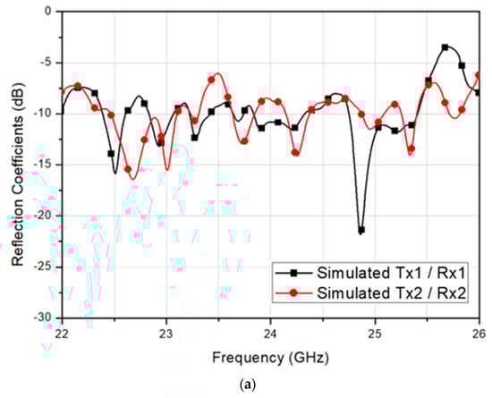
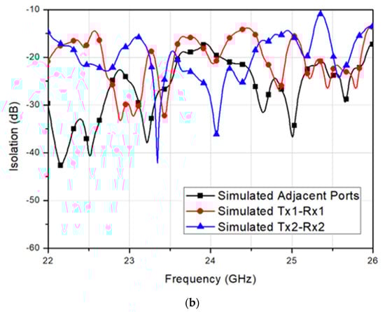
Figure 4.
Simulated (a) reflection coefficient and (b) isolation of the 2-Tx and 2-Rx antenna module without the guide-rings.
Since Tx1 and Tx2 are symmetric with Rx1 and Rx2, only two plots representing each symmetric pair are presented for better visibility in Figure 4a. It should be noted that the individual array has been matched at 24 GHz, but the integration of four arrays resulted in a deviation in reflection coefficients. The reflection coefficients were unstable, where each polarization antenna pair showed different return loss. The Tx2 and Rx2 antennas had the impedances unmatched at the center frequency, whereas Tx1 and Rx1 satisfied the matching at 24 GHz, as shown in Figure 4a. Further, it should be noted that since Tx1 and Tx2 were symmetric with Rx1 and Rx2, the symmetric coupling results other than Tx1-to-Rx1 and Tx2-to-Rx2 were denoted as adjacent ports, while identical plots were omitted for better visibility in Figure 4b. Without having the guide-rings, the simulated minimum isolation of 18 dB was observed between Rx1 and Rx2 antennas at 24 GHz. Thus, referring to the parameters described in Figure 2b, the guide-ring was added and optimized by using CST simulation. The distance between the patch and the guide-ring, d1, was determined by comparing the reflection coefficient tendency of the four-array to a single-array standalone case. Then, the simulated reflection coefficient and isolation with respect to the guide-ring via radius were achieved, as shown in Figure 5.
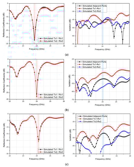
Figure 5.
Simulated reflection coefficient and isolation of the 2-Tx and 2-Rx antenna with a guide-ring vias having a radius of (a) 0.1 mm (b) 0.15 mm and (c) 0.2 mm.
As previously mentioned, the redundant plots due to the antenna symmetry are omitted again in Figure 5. When the guide-ring via radius was set to 0.1 mm, the center frequency was observed at a slightly lower frequency than 24 GHz, as shown in Figure 5a. As the via radius increased, the center frequency shifted slightly higher, as shown in Figure 5b,c. The simulated minimum isolations at 24 GHz for via radius of 0.1 mm, 0.15 mm, and 0.2 mm were 41.9 dB, 36.7 dB, and 38.3 dB, respectively, whereas the maximum isolations were 43.5 dB, 54.4 dB, and 61.3 dB, respectively. Although the minimum isolation characteristic was shown the best with the via radius of 0.1 mm, the target frequency must be satisfied, and thus, the via radius was chosen as 0.15 mm.
Thus, the effect of the distance between each via, d2, on the reflection coefficient and isolation were further simulated, as shown in Figure 6. When the guide-ring vias were placed with a distance of 0.5 mm, the center frequency was observed at a slightly higher frequency than 24 GHz, as shown in Figure 6a. As the via distance increases, the center frequency shifted slightly lower, as shown in Figure 6b,c. The simulated minimum isolations at 24 GHz for via distance of 0.5 mm, 1.0 mm, and 1.5 mm were 39.4 dB, 36.7 dB, and 34.7 dB, respectively, whereas the maximum isolations were 59.7 dB, 54.4 dB, and 45.5 dB, respectively. Although the minimum isolation characteristic was shown the best with the via separation distance of 0.5 mm, the target frequency must be satisfied, and thus, the via distance was chosen as 1.0 mm.
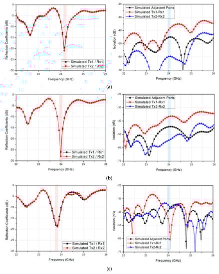
Figure 6.
Simulated reflection coefficient and isolation of the 2-Tx and 2-Rx antenna with the guide-ring via having a separation distance of (a) 0.5 mm (b) 1.0 mm, and (c) 1.5 mm.
To verify the isolation enhancement through the guide-ring effect, the surface current distribution at 24 GHz was simulated by a single port excitation with and without guide-ring vias at different phases within a period, as shown in Figure 7. Again, the simulation was conducted by CST, where hexahedral mesh at 26 GHz (for 22 GHz to 26 GHz band) with –25 dB accuracy was set.
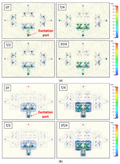
Figure 7.
Simulated surface current distribution by a single port excitation for the antennas (a) without guide-rings and (b) with guide-rings at 24 GHz with different phases within a period.
Figure 7a shows the surface current spreading all over the ground plane and flowing to the neighboring antennas. These surface currents directly leaked to the other antennas and thereby caused the impedance instability and isolation degradation. To prevent the multi-channel antenna isolation from being degraded and unstable, the proposed structure adopted guide rings for each array. As shown in Figure 7b, the surface current was strongly held inside the guide ring, resulting in a stronger field excitation for the desired antenna array, whereas the unwanted surface current leaking to the neighboring antenna arrays is significantly reduced. Thus, higher antenna port-to-port isolation characteristic among multiple antenna arrays can be achieved compared to the simple combination of orthogonal antenna placement.
However, by simply having the guide-ring cannot guarantee the antenna performance because the area for the surface current that can be circulated gets changed by the magnetic walls. That is, the antenna impedance for each array should be optimized by taking the guide-ring into account. Thus, the proposed feed network adopted an integrated feed network connected with a vertical matching stub on the top-layer, as described in Figure 3. Then, to verify the S-parameters of the proposed antenna module, the reflection coefficient and isolation for the 2-TX and 2-Rx with the guide-rings and matching stubs were simulated, as shown in Figure 8.
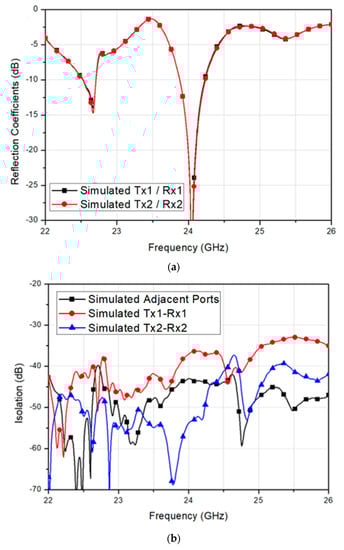
Figure 8.
Simulated (a) reflection coefficient and (b) isolation magnitude of the 2-Tx and 2-Rx antenna module with the guide-rings and feed network impedance matching stubs.
All antennas with the guide-rings showed identical reflection coefficients with the center frequency at 24 GHz, as shown in Figure 8a. The simulated 10-dB impedance bandwidth of the proposed antenna is 357 MHZ corresponded to a fractional bandwidth of 1.49%. Also, the simulated minimum isolation of 37.1 dB was observed between Tx1 and Rx1 at 24 GHz, resulting in the minimum isolation enhanced by 206% approximately, as shown in Figure 8b. Further, the maximum isolation level is about 53.9 dB and achieved by Tx2-to-Rx2 path. Then, the 3-D radiation patterns for co-polarization and cross-polarization characteristics of the proposed 2-Tx and 2-Rx antenna module was simulated, as shown in Figure 9.
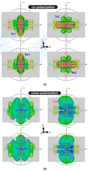
Figure 9.
Simulated 3-D radiation patterns of the proposed antenna module with (a) co-polarization patterns and (b) cross-polarization patterns for each channel.
To clarify the radiation characteristics, the polar patterns for each array in the corresponding radiation planes are presented in Figure 10. The simulated peak gain of Tx1, Tx2, Rx1, and Rx2 were 12.0 dBi, 11.9 dBi, 12.0 dBi, and 11.9 dBi, respectively. The simulated half-power beamwidth (HPBW) for Tx1, Tx2, Rx1, and Rx2 in xz plane were 24°, 49°, 24°, and 49°, respectively, while the simulated HPBW in yz plane for Tx1, Tx2, Rx1, and Rx2 were and 46°, 24°, 42° and 24°, respectively. Further, the simulated 0-dB beamwidth for Tx1, Tx2, Rx1, and Rx2 in xz plane were 48°, 122°, 48°, and 122°, respectively. Lastly, the simulated 0-dB beamwidth for Tx1, Tx2, Rx1, and Rx2 in yz plane were 129°, 46°, 130°, and 46°, respectively. It should be noted that the simulated cross-polarizations of Tx1 and Rx1 in yz plane and Tx2 and Rx2 in xz plane were normalized by −40 dB in Figure 10 since the levels were extremely small. These simulated radiation patterns will be also compared with the measured results in the next section.
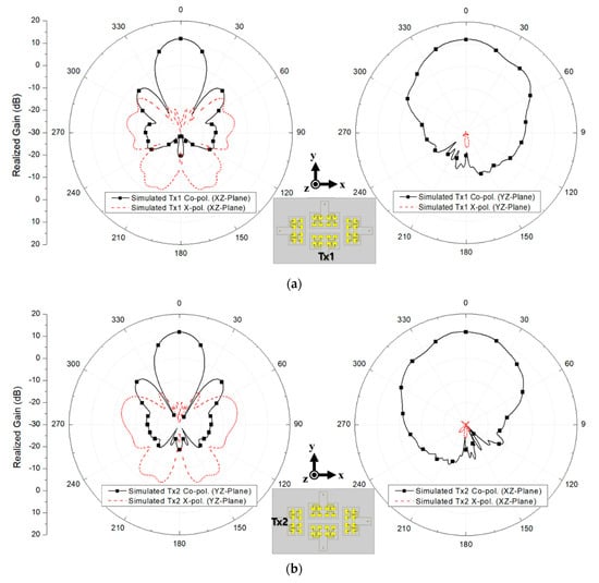
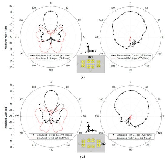
Figure 10.
Simulated radiation patterns for (a) Tx1, (b) Tx2, (c) Rx1 and (d) Rx2 in xz and yz planes.
3. Measured Results
The proposed 2-Tx and 2-Rx antenna module was fabricated with the 4-layer PCB configured by RF-35 Taconic substrates having a relative permittivity of 3.5 and loss tangent of 0.0018, and RO4450B prepregs having a relative permittivity of 3.35 and loss tangent of 0.004, as shown in Figure 11a. The detailed layer information can be referred to in Figure 3b in the previous section. The fabricated dimension of the proposed antenna module, including the test jig and excluding the RF connectors, was 8.09 λ0 x 5.60 λ0 x 0.53 λ0 at 24 GHz. It is noted that the actual antenna PCB occupation, including the ground plane, was 7.52 λ0 x 5.04 λ0. Then, the S-parameters were measured by Keysight N5227B PNA vector network analyzer, and the radiation patterns of the proposed antenna were measured with a near-field scanning at a mmWave anechoic antenna chamber, as shown in Figure 11b.
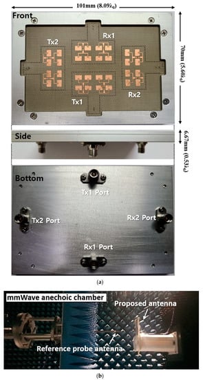
Figure 11.
The proposed 2-Tx and 2-Rx antenna module: (a) fabrication photo and (b) measurement setup at mmWave anechoic chamber.
Figure 12a shows the measured reflection coefficient of the fabricated 2-Tx and 2-Rx antenna module in comparison with the simulated results. The measured 10-dB impedance bandwidths of the Tx1, Tx2, Rx1, and Rx2 were 552 MHz, 679 MHz, 679 MHz, and 931 MHz, resulting in fractional bandwidths of 2.3%, 2.8%, 2.8%, and 3.9%, respectively. The measured bandwidths were a little wider than the simulated bandwidths due to the effect of test jig and real RF connectors. Nevertheless, the measured reflection coefficient showed a good agreement with the simulated result.
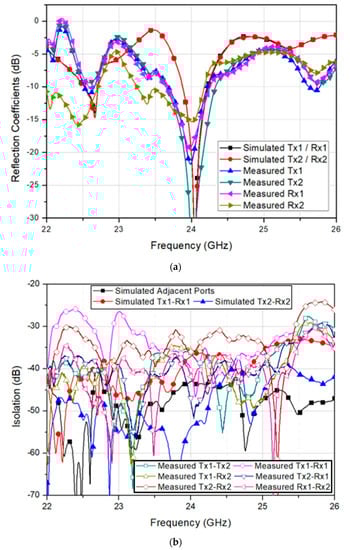
Figure 12.
Simulated and measured (a) reflection coefficients and (b) isolation characteristics of the fabricated 2-Tx and 2-Rx antenna module.
Further, Figure 12b shows the measured isolation characteristics among Tx and Rx arrays in comparison with the simulated results. The minimum measured isolation was found by 35.6 dB between Tx1 and Rx2, whereas the maximum measured isolation of 47.0 dB was achieved by Tx2-to-Rx1 path. Therefore, both measured and simulated isolation characteristics showed high isolation among Tx and Rx arrays, and a good agreement. Once the measured S-parameters had been verified by showing good performances, the radiation patterns were also measured at an anechoic antenna chamber and compared with the simulated results at 24 GHz. The measurement results are shown in Figure 13.
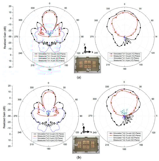
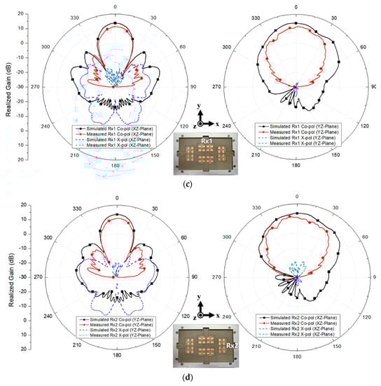
Figure 13.
Measured radiation patterns for (a) Tx1, (b) Tx2, (c) Rx1, and (d) Rx2 in xz and yz planes.
The measured peak gain for Tx1, Tx2, Rx1, and Rx2 were 11.7 dBi, 11.4 dBi, 11.6 dBi, and 11.6 dBi, respectively. The slight decrease in the realized gain compared to the simulated gain was due to the RF connector loss. Further, the measured HPBW in xz plane for Tx1, Tx2, Rx1, and Rx2 were 24°, 35°, 23° and 36°, respectively, whereas the measured HPBW in yz plane for Tx1, Tx2, Rx1, and Rx2 were 37°, 21°, 34° and 21°, respectively. The measured 0-dB beamwidths for Tx1, Tx2, Rx1, and Rx2 in xz plane were 45°, 89°, 46°, and 88°, respectively. Lastly, the measured 0-dB beamwidths for Tx1, Tx2, Rx1, and Rx2 in yz plane were 89°, 44°, 84°, and 44°, respectively. Although the measured beamwidths were smaller than the simulated beamwidths due to the inclusion of the test jig, the measurement showed a reasonable range of agreement with the simulation regarding the performance tendency. The measured results are summarized in Table 1 and verify the high channel-to-channel isolation with good radiation characteristics at 24 GHz applications.

Table 1.
Summary of the measured performance for the proposed 2-Tx and 2-Rx antenna module.
Finally, the performance comparison of the proposed antenna module with the other antennas is summarized in Table 2, showing the excellent isolation characteristic of the proposed structure.
Table 2.
Performance comparison of the proposed antenna module with various topologies.
4. Conclusions
The dual-polarized, high gain multi-beam, and high T/Rx channel-to-channel isolation antenna module for 24 GHz applications have been presented. The proposed antenna module consisted of 2-TX and 2-Rx, where each antenna was configured by 2 × 4 array with a guide-ring and a matching stub to ensure high isolation and stabilized matching performances. The proposed antenna module was fabricated by 4-layer PCB process and showed a good agreement between the simulated and measured results. The measured 10-dB impedance bandwidths for Tx1, Tx2, Rx1, and Rx2 were 2.3%, 2.8%, 2.8%, and 3.9%, respectively, while the measured minimum isolation among the arrays was suppressed below 35.6 dB at 24 GHz. Moreover, the highest isolation achieved at 24 GHz was about 47 dB. Further, the measured peak gains for Tx1, Tx2, Rx1, and Rx2 were 11.7 dBi, 11.4 dBi, 11.6 dBi, and 11.6 dBi, respectively, including the feed loss. The measured HPBW in xz plane for Tx1, Tx2, Rx1, and Rx2 were 24°, 35°, 23° and 36°, respectively, whereas the measured HPBW in yz plane for Tx1, Tx2, Rx1, and Rx2 were 37°, 21°, 34° and 21°, respectively. Lastly, the measured 0-dB beamwidths for Tx1, Tx2, Rx1, and Rx2 in xz plane were 45°, 89°, 46°, and 88°, respectively, whereas the measured 0-dB beamwidths for Tx1, Tx2, Rx1, and Rx2 in yz plane were 89°, 44°, 84°, and 44°, respectively. Thus, the proposed antenna module can be efficiently used for multi-channel radar sensor applications such as smart IoT-based environments where strong Tx leakages to Rx chain can be greatly suppressed, resulting in an enhanced dynamic range for both Tx and Rx operation.
Author Contributions
Writing-original draft preparation, Y.-J.K.; investigation and validation, G.N.; writing-review and editing, and supervision, H.L.L.; formal analysis validation, S.Y. All authors have read and agreed to the published version of the manuscript.
Funding
This research was funded by the Institute of Information and Communications Technology Planning and Evaluation (IITP) and Chung-Ang University.
Acknowledgments
This research was supported by the Institute of Information and Communications Technology Planning and Evaluation (IITP) grant funded by the Korea government (MSIT) (No.2019-0-00138, Development of Intelligent Radar Platform Technology for Smart Environments and No. 2017-0-00795, A Study on a Small Antenna System for Vehicle Supporting Wide Elevation Angle), and Chung-Ang University Research Scholarship Grants in 2019.
Conflicts of Interest
The authors declare no conflict of interest.
References
- Yang, B.; Zhang, J. Physical Layer Secret-Key Generation Scheme for Transportation Security Sensor Network. Sensors 2017, 17, 1524. [Google Scholar] [CrossRef] [PubMed]
- Gonzalez, H.; Rodriguez, S.; Elouardi, A. Track-Before-Detect Framework-Based Vehicle Monocular Vision Sensors. Sensors 2019, 19, 560. [Google Scholar] [CrossRef] [PubMed]
- Jeng, S.-L.; Chieng, W.-H.; Lu, H.-P. Estimating Speed Using a Side-Looking Single-Radar Vehicle Detector. IEEE Trans. Intell. Transp. Syst. 2014, 2, 607–614. [Google Scholar] [CrossRef]
- Tan, R.; Xing, G.; Wang, J.; So, H.C. Exploiting Reactive Mobility for Collaborative Target Detection in Wireless Sensor Networks. IEEE Trans. Mob. Comput. 2010, 3, 317–332. [Google Scholar] [CrossRef]
- David, F.-M.; José-Tomás, G.-P.; Pablo, A.-G.; Mateo, B.-G. Vehicular Traffic Surveillance and Road Lane Detection Using Radar Interferometry. IEEE Trans. Veh. Technol. 2012, 3, 959–970. [Google Scholar]
- Feng, Z.; Li, M.; Stolz, M.; Kunert, M.; Wiesbeck, W. Lane Detection with a High-Resolution Automotive Radar by Introducing a New Type of Road Marking. IEEE Trans. Intell. Transp. Syst. 2019, 7, 2430–2447. [Google Scholar] [CrossRef]
- Sang, P.; Heo, J.; Park, H.; Baac, H. Photoacoustic Energy Sensor for Nanosecond Optical Pulse Measurement. Sensors 2018, 18, 3879. [Google Scholar] [CrossRef]
- Lin, F.-T.; Kuo, Y.-C.; Hsieh, J.-C.; Tsai, H.-Y.; Liao, Y.-T.; Lee, H.-C. A Self-Powering Wireless Environment Monitoring System Using Soil Energy. IEEE Sens. 2015, 7, 3751–3758. [Google Scholar] [CrossRef]
- Huang, W.-D.; Deb, S.; Seo, Y.; Rao, S.; Chiao, M.; Chiao, J.C. A Passive Radio-Frequency pH-Sensing Tag for Wireless Food-Quality Monitoring. IEEE Sens. 2012, 3, 487–495. [Google Scholar] [CrossRef]
- Farhat, H.; Iliev, P.; Marriage, P.; Rolland, N. An Added Value Alternative to RAIN RFID Items Characterization in Retail. IEEE Access 2018, 6, 32430–32439. [Google Scholar] [CrossRef]
- Shao, S.; Burkholder, R.J. Item-Level RFID Tag Location Sensing Utilizing Reader Antenna Spatial Diversity. IEEE Sens. 2013, 10, 3767–3774. [Google Scholar] [CrossRef]
- Brisimi, T.S.; Cassandras, C.G.; Osgood, C.; Paschalidis, I.C.; Zhang, Y. Sensing and Classifying Roadway Obstacles in Smart Cities: The Street Bump System. IEEE Access 2016, 4, 1301–1312. [Google Scholar] [CrossRef]
- D’Amico, G.; L’Abbate, P.; Liao, W.; Yigitcanlar, T.; Ioppolo, G. Understanding Sensor Cities: Insights from Technology Giant Company Driven Smart Urbanism Practices. Sensors 2020, 16, 4391. [Google Scholar] [CrossRef]
- Islam, S.M.R.; Kwak, D.; Kabir, M.H.; Hossain, M.; Kwak, K.-S. The Internet of Things for Health Care: A Comprehensive Survey. IEEE Access 2015, 3, 678–708. [Google Scholar] [CrossRef]
- Lee, Y.K.; Jo, J.; Shin, H.S. Development and Evaluation of a Wristwatch-Type Photoplethysmography Array Sensor Module. IEEE Sens. 2013, 13, 1459–1463. [Google Scholar] [CrossRef]
- Kang, Y.S.; Park, I.-H.; Rhee, J.; Lee, Y.-H. MongoDB-Based Repository Design for IoT-Generated RFID/Sensor Big Data. IEEE Sens. J. 2016, 16, 485–497. [Google Scholar] [CrossRef]
- Mondal, S.; Wijewardena, K.P.; Karuppuswami, S.; Kriti, N.; Kumar, D.; Chahal, P. Blockchain Inspired RFID-Based Information Architecture for Food Supply Chain. IEEE Internet Things J. 2019, 6, 5803–5813. [Google Scholar] [CrossRef]
- Shousong, C.; Xiaoguang, W.; Yuanjun, Z. Revenue Model of Supply Chain by Internet of Things Technology. IEEE Access 2019, 7, 4091–4100. [Google Scholar] [CrossRef]
- Hu, Z.; Xu, L.; Cao, L.; Liu, S.; Luo, Z.; Wang, J.; Li, X.; Wang, L. Application of Non-Orthogonal Multiple Access in Wireless Sensor Networks for Smart Agriculture. IEEE Access 2019, 7, 87582–87592. [Google Scholar] [CrossRef]
- Balan, T.; Dumitru, C.; Dudnik, G.; Alessi, E.; Lesecq, S.; Correvon, M.; Passaniti, F.; Licciardello, A. Smart Multi-Sensor Platform for Analytics and Social Decision Support in Agriculture. Sensors 2020, 20, 4127. [Google Scholar] [CrossRef]
- Zhang, X.; Pipattanasomporn, M.; Chen, T.; Rahman, S. An IoT-Based Thermal Model Learning Framework for Smart Buildings. IEEE Internet Things J. 2020, 7, 518–527. [Google Scholar] [CrossRef]
- Nugur, A.; Pipattanasomporn, M.; Kuzlu, M.; Rahman, S. Design and Development of an IoT Gateway for Smart Building Applications. IEEE Internet Things J. 2019, 6, 9020–9029. [Google Scholar] [CrossRef]
- Minoli, D.; Sohraby, K.; Occhiogrosso, B. IoT Considerations, Requirements, and Architectures for Smart Buildings—Energy Optimization and Next-Generation Building Management Systems. IEEE Internet Things J. 2017, 4, 269–283. [Google Scholar] [CrossRef]
- Cheng, C.-T.; Ganganath, N.; Fok, K.-Y. Concurrent Data Collection Trees for IoT Applications. IEEE Trans. Ind. Informat. 2017, 13, 793–799. [Google Scholar] [CrossRef]
- Fu, J.-S.; Liu, Y.; Chao, H.-C.; Bhargava, B.K.; Zhang, Z.-J. Secure Data Storage and Searching for Industrial IoT by Integrating Fog Computing and Cloud Computing. IEEE Trans. Ind. Informat. 2018, 14, 4519–4528. [Google Scholar] [CrossRef]
- Tao, H.; Bhuiyan, M.Z.A.; Abdalla, A.N.; Hassan, M.M.; Zain, J.M.; Hayajneh, T. Secured Data Collection with Hardware-Based Ciphers for IoT-Based Healthcare. IEEE Internet Things J. 2019, 6, 410–420. [Google Scholar] [CrossRef]
- Wang, S.; Yuan, J.; Li, X.; Qian, Z.; Arena, F.; You, I. Active Data Replica Recovery for Quality-Assurance Big Data Analysis in IC-IoT. IEEE Access 2019, 7, 106997–107005. [Google Scholar] [CrossRef]
- Batool, S.; Hassan, A.; Saqib, N.A.; Khattak, M.A.K. Authentication of Remote IoT Users Based on Deeper Gait Analysis of Sensor Data. IEEE Access 2020, 8, 101784–101796. [Google Scholar] [CrossRef]
- Mohammadi, M.; Al-Fuqaha, A.; Sorour, S.; Guizani, M. Deep Learning for IoT Big Data and Streaming Analytics: A Survey. IEEE Commun. Surv. Tutor. 2018, 20, 2923–2960. [Google Scholar] [CrossRef]
- Kannan, R.; Jain, S. Adaptive Recalibration Algorithm for Removing Sensor Errors and Its Applications in Motion Tracking. IEEE Sens. J. 2018, 18, 2916–2924. [Google Scholar] [CrossRef]
- Rana, M.M.; Bo, R. IoT-Based Improved Human Motion Estimations Method under Cyber Attacks. IEEE Internet Things J. 2019, 6, 10934–10935. [Google Scholar] [CrossRef]
- Zhou, H.; Yang, G.; Lv, H.; Huang, X.; Yang, H.; Pang, Z. IoT-Enabled Dual-Arm Motion Capture and Mapping for Telerobotics in Home Care. IEEE J. Biomed. Health Inform. 2020, 24, 1541–1549. [Google Scholar] [CrossRef]
- Diao, J.; Zhao, D.; Wang, J.; Nguyen, H.M.; Tang, J.; Zhou, Z. Energy-Efficient Boundary Detection of Continuous Objects in IoT Sensing Networks. IEEE Sens. J. 2019, 19, 8303–8316. [Google Scholar] [CrossRef]
- Saha, P.; Mukhopadhyay, S. Multispectral Information Fusion with Reinforcement Learning for Object Tracking in IoT Edge Devices. IEEE Sens. J. 2020, 20, 4333–4344. [Google Scholar] [CrossRef]
- Xiong, J.; Lu, L.; Wang, H.; Yang, J.; Gui, G. Object-Level Trajectories Based Fine-Grained Action Recognition in Visual IoT Applications. IEEE Access 2019, 7, 103629–103638. [Google Scholar] [CrossRef]
- Haghi, M.; Neubert, S.; Geissler, A.; Fleischer, H.; Stoll, N.; Stoll, R.; Thurow, K. A Flexible and Pervasive IoT-Based Healthcare Platform for Physiological and Environmental Parameters Monitoring. IEEE Internet Things J. 2020, 7, 5628–5647. [Google Scholar] [CrossRef]
- Zhuang, T.; Ren, M.; Gao, X.; Dong, M.; Huang, W.; Zhang, C. Insulation Condition Monitoring in Distribution Power Grid via IoT-Based Sensing Network. IEEE Trans. Power Del. 2019, 34, 1706–1714. [Google Scholar] [CrossRef]
- Xu, G. IoT-Assisted ECG Monitoring Framework with Secure Data Transmission for Health Care Applications. IEEE Access 2020, 8, 74586–74594. [Google Scholar] [CrossRef]
- Wang, G.; Nixon, M.; Boudreaux, M. Toward Cloud-Assisted Industrial IoT Platform for Large-Scale Continuous Condition Monitoring. Proc. IEEE. 2019, 107, 1193–1205. [Google Scholar] [CrossRef]
- Roy, D.S.; Behera, R.K.; Reddy, K.H.K.; Buyya, R. A Context-Aware Fog Enabled Scheme for Real-Time Cross-Vertical IoT Applications. IEEE Internet Things J. 2019, 6, 2400–2412. [Google Scholar]
- Perera, C.; Zaslavsky, A.; Christen, P.; Georgakopoulos, D. Context Aware Computing for The Internet of Things: A Survey. IEEE Commun. Surv. Tutor. 2014, 16, 414–454. [Google Scholar] [CrossRef]
- Kamienski, C.A.; Borelli, F.F.; Biondi, G.O.; Pinheiro, I.; Zyrianoff, I.D.; Jentsch, M. Context Design and Tracking for IoT-Based Energy Management in Smart Cities. IEEE Internet Things J. 2018, 5, 687–695. [Google Scholar] [CrossRef]
- Arfaoui, A.; Cherkaoui, S.; Kribeche, A.; Senouci, S.M. Context-Aware Adaptive Remote Access for IoT Applications. IEEE Internet Things J. 2020, 7, 786–799. [Google Scholar] [CrossRef]
- Cao, N.; Nasir, S.B.; Sen, S.; Raychowdhury, A. Self-Optimizing IoT Wireless Video Sensor Node with In-Situ Data Analytics and Context-Driven Energy-Aware Real-Time Adaptation. IEEE Trans. Circuits Syst. I Reg. Pap. 2017, 64, 2470–2480. [Google Scholar] [CrossRef]
- Bechter, J.; Rameez, M.; Waldschmidt, C. Analytical and Experimental Investigations on Mitigation of Interference in a DBF MIMO Radar. IEEE Trans. Microw. Theory Techn. 2017, 65, 1727–1734. [Google Scholar] [CrossRef]
- Brooker, G.M. Mutual Interference of Millimeter-Wave Radar Systems. IEEE Trans. Electromagn. Compat. 2007, 49, 170–181. [Google Scholar] [CrossRef]
- Jin, F.; Cao, S. Automotive Radar Interference Mitigation Using Adaptive Noise Canceller. IEEE Trans. Veh. Technol. 2019, 68, 3747–3754. [Google Scholar] [CrossRef]
- Bereketli, A.; Akan, O.B. Communication coverage in wireless passive sensor networks. IEEE Commun. Lett. 2009, 13, 133–135. [Google Scholar] [CrossRef]
- Yamada, S.; Choudhury, D.; Thakkar, C.; Chakrabarti, A.; Dasgupta, K.; Daneshgar, S.; Horine, B.D. Cross-Polarization Discrimination and Port-to-Port Isolation Enhancement of Dual-Polarized Antenna Structures Enabling Polarization MIMO. IEEE Antennas Wirel. Propag. Lett. 2019, 18, 2409–2413. [Google Scholar] [CrossRef]
- Liu, D.; Gu, X.; Baks, C.W.; Valdes-Garcia, A. Antenna-in-Package Design Considerations for Ka-Band 5G Communication Applications. IEEE Trans. Antennas Propag. 2017, 65, 6372–6379. [Google Scholar] [CrossRef]
- Kim, C.-Y.; Kim, J.-G.; Baek, D.; Hong, S. A Circularly Polarized Balanced Radar Front-End With a Single Antenna for 24-GHz Radar Applications. IEEE Trans. Microw. Theory Tech. 2009, 57, 293–297. [Google Scholar]
- Mirmozafari, M.; Zhang, G.; Saeedi, S.; Doviak, R.J. A Dual Linear Polarization Highly Isolated Crossed Dipole Antenna for MPAR Application. IEEE Antennas Wirel. Propag. Lett. 2017, 16, 1879–1882. [Google Scholar] [CrossRef]
- Saeidi-Manesh, H.; Zhang, G. High-Isolation, Low Cross-Polarization, Dual- Polarization, Hybrid Feed Microstrip Patch Array Antenna for MPAR Application. IEEE Trans. Antennas Propag. 2018, 66, 2326–2332. [Google Scholar] [CrossRef]
- Feng, D.; Zhai, H.; Xi, L.; Yang, S.; Zhang, K.; Yang, D. A Broadband Low-Profile Circular-Polarized Antenna on an AMC Reflector. IEEE Antennas Wirel. Propag. Lett. 2017, 16, 2840–2843. [Google Scholar] [CrossRef]
- Chen, Y.-C.; Chen, S.-Y.; Hsu, P. A Modified CPW-Fed Slot Loop Antenna with Reduced Cross Polarization and Size. IEEE Antennas Wirel. Propag. Lett. 2011, 10, 1124–1126. [Google Scholar] [CrossRef]
- Kong, L.; Xu, X. A Compact Dual-Band Dual-Polarized Microstrip Antenna Array for MIMO-SAR Applications. IEEE Trans. Antennas Propag. 2018, 66, 2374–2381. [Google Scholar] [CrossRef]
- Kang, L.; Li, H.; Wang, X.; Shi, X. Compact Offset Microstrip-Fed MIMO Antenna for Band-Notched UWB Applications. IEEE Antennas Wirel. Propag. Lett. 2015, 14, 1754–1757. [Google Scholar] [CrossRef]
- Malik, J.; Patnaik, A.; Kartikeyan, M.V. Novel Printed MIMO Antenna with Pattern and Polarization Diversity. IEEE Antennas Wirel. Propag. Lett. 2015, 14, 739–742. [Google Scholar] [CrossRef]
- Wu, Q.; Hirokawa, J.; Yin, J.; Yu, C.; Wang, H.; Hong, W. Millimeter-Wave Multibeam Endfire Dual-Circularly Polarized Antenna Array for 5G Wireless Applications. IEEE Trans. Antennas Propag. 2018, 66, 4930–4935. [Google Scholar] [CrossRef]
- Chun-Xu, M.; Gao, S.; Luo, Q.; Rommel, T.; Chu, Q.-X. Low-Cost X/Ku/Ka-Band Dual-Polarized Array with Shared Aperture. IEEE Trans. Antennas Propag. 2017, 65, 3520–3527. [Google Scholar]
- Chu, H.; Guo, Y.-X. A Filtering Dual-Polarized Antenna Subarray Targeting for Base Stations in Millimeter-Wave 5G Wireless Communications. IEEE Trans. Compon. Packag. Manuf. Technol. 2017, 7, 964–973. [Google Scholar] [CrossRef]
- Hussain, N.; Jeong, M.-J.; Park, J.; Kim, N. A Broadband Circularly Polarized Fabry-Perot Resonant Antenna Using a Single-Layered PRS for 5G MIMO Applications. IEEE Access 2019, 7, 42897–42907. [Google Scholar] [CrossRef]
- Li, T.; Chen, Z.N. Metasurface-Based Shared-Aperture 5G S -/ K -Band Antenna Using Characteristic Mode Analysis. IEEE Trans. Antennas Propag. 2018, 66, 6742–67503. [Google Scholar] [CrossRef]
- Ding, Y.R.; Cheng, Y.J. Ku/Ka Dual-Band Dual-Polarized Shared-Aperture Beam-Scanning Antenna Array with High Isolation. IEEE Trans. Antennas Propag. 2019, 67, 2413–2422. [Google Scholar] [CrossRef]
© 2020 by the authors. Licensee MDPI, Basel, Switzerland. This article is an open access article distributed under the terms and conditions of the Creative Commons Attribution (CC BY) license (http://creativecommons.org/licenses/by/4.0/).