Experimental and Numerical Investigation on the Strain Response of Distributed Optical Fiber Sensors Bonded to Concrete: Influence of the Adhesive Stiffness on Crack Monitoring Performance

 ,
,  ,
, 

Abstract
1. Introduction
- -
- using bare OF sensors (including their primary coating) that are bonded to the concrete surface with a polymer adhesive; and
- -
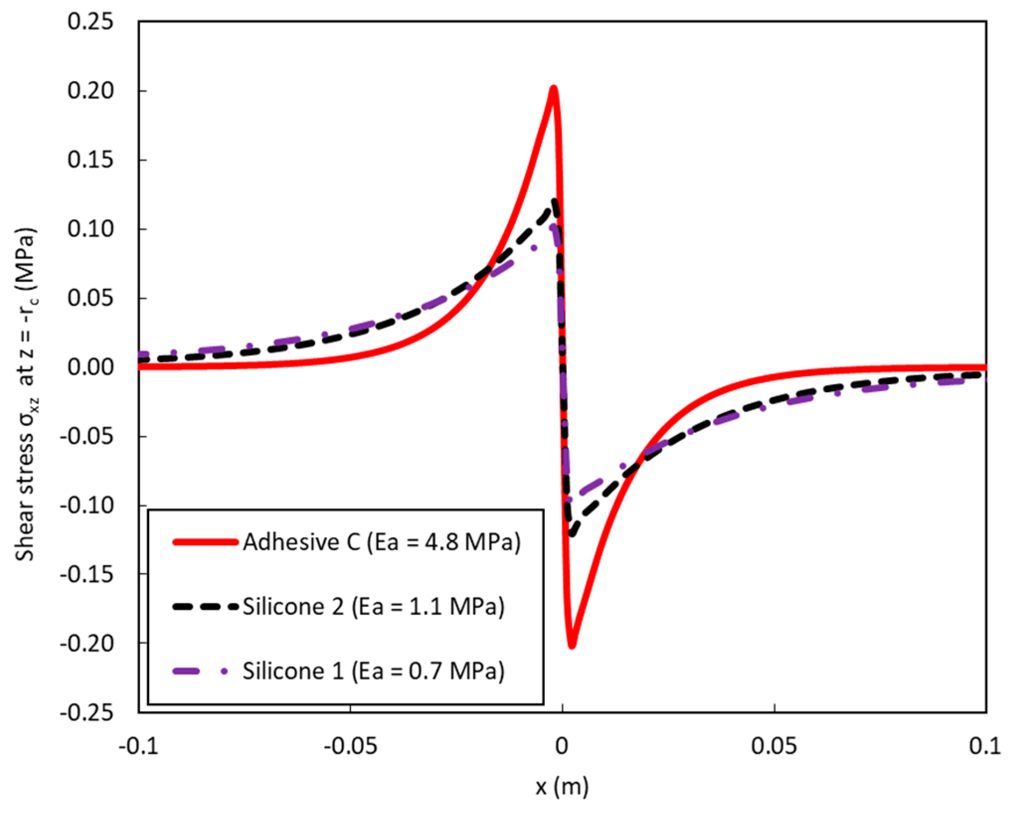
- optimizing the mechanical properties of this intermediate adhesive layer in order to mitigate local stress concentrations along the DOFS arising from crack development in concrete, while maintaining a good level of performance for crack detection. In this configuration, strain from the host structure is transferred through the adhesive layer only, which deforms mainly under shear stress [26]. Consequently, the measurement sensitivity of the bonded sensor depends strongly on the characteristics of this adhesive layer.
2. Theoretical Analysis of the Strain Transfer Process between Concrete/Bonded DOFS
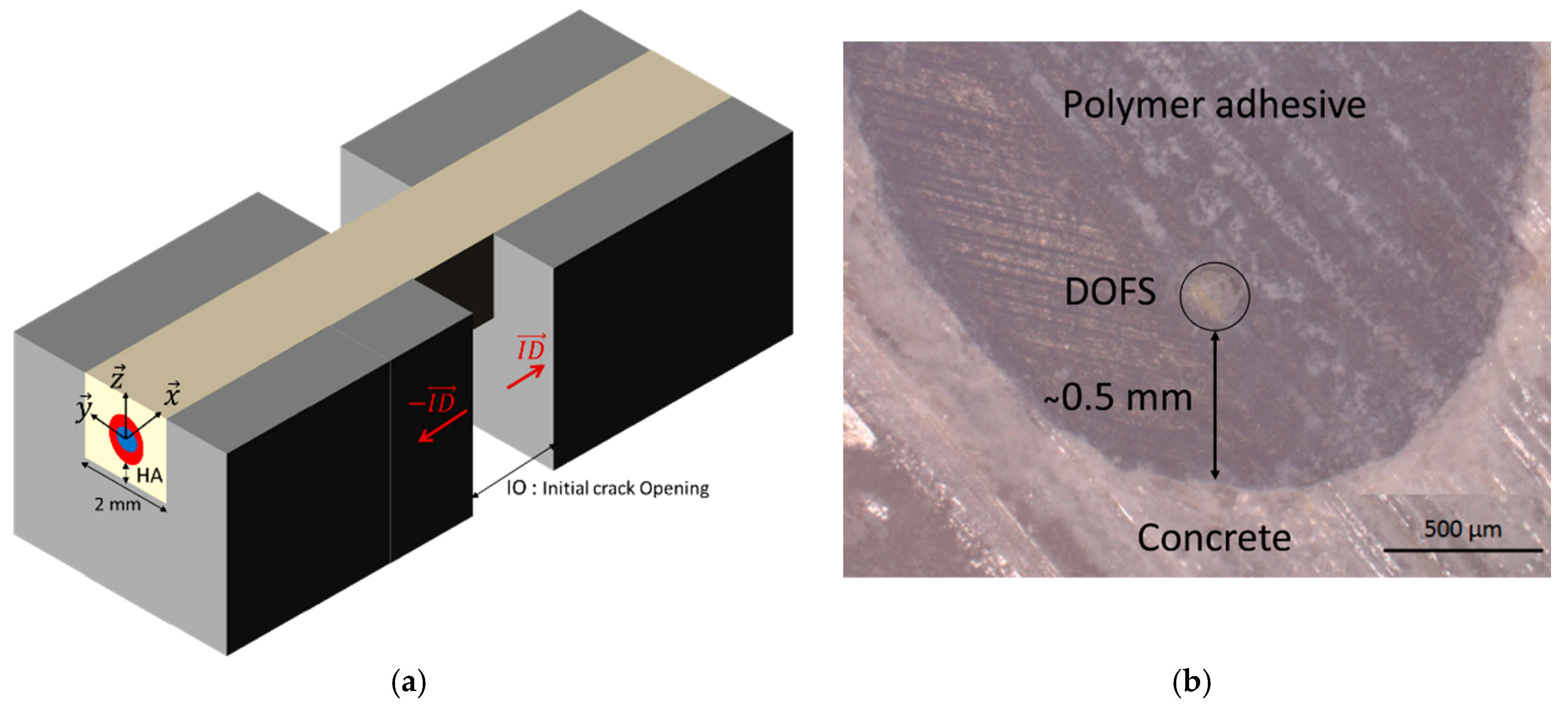
2.1. Representative Model Configuration
2.2. Analytical Approach
2.3. Comparison between Analytical and Numerical Approaches
3. Experimental Studies
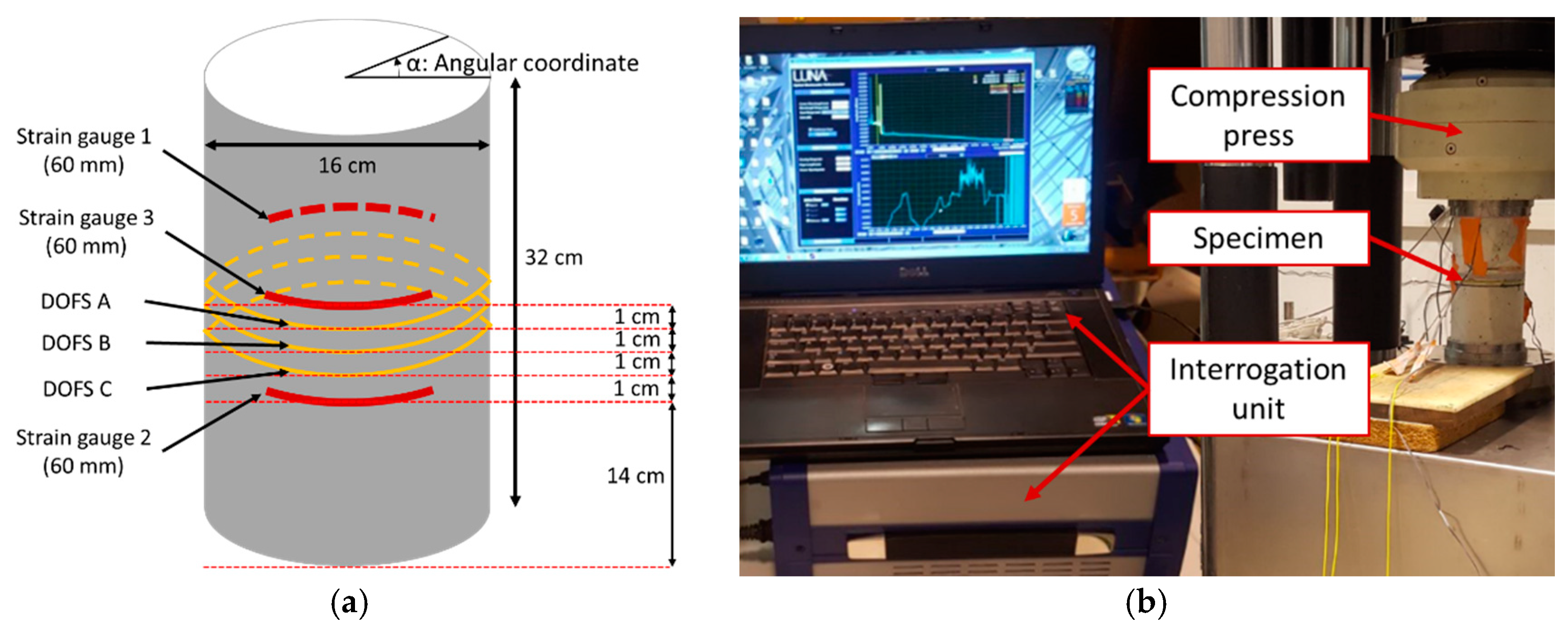
3.1. Compression Test on a Concrete Cylinder
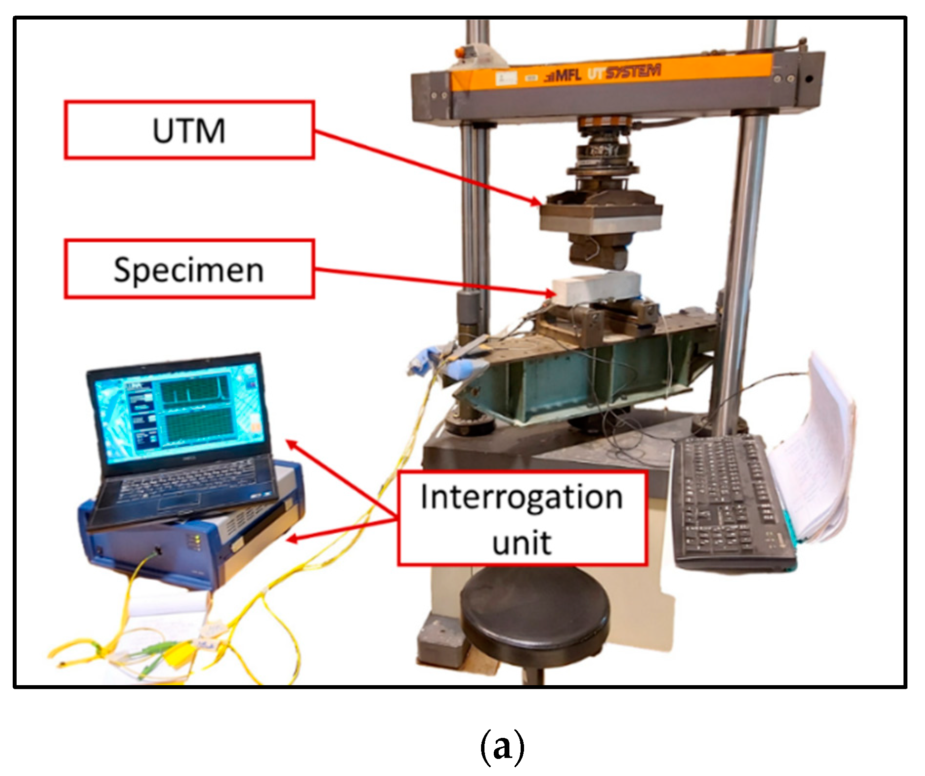
3.1.1. Test Procedure
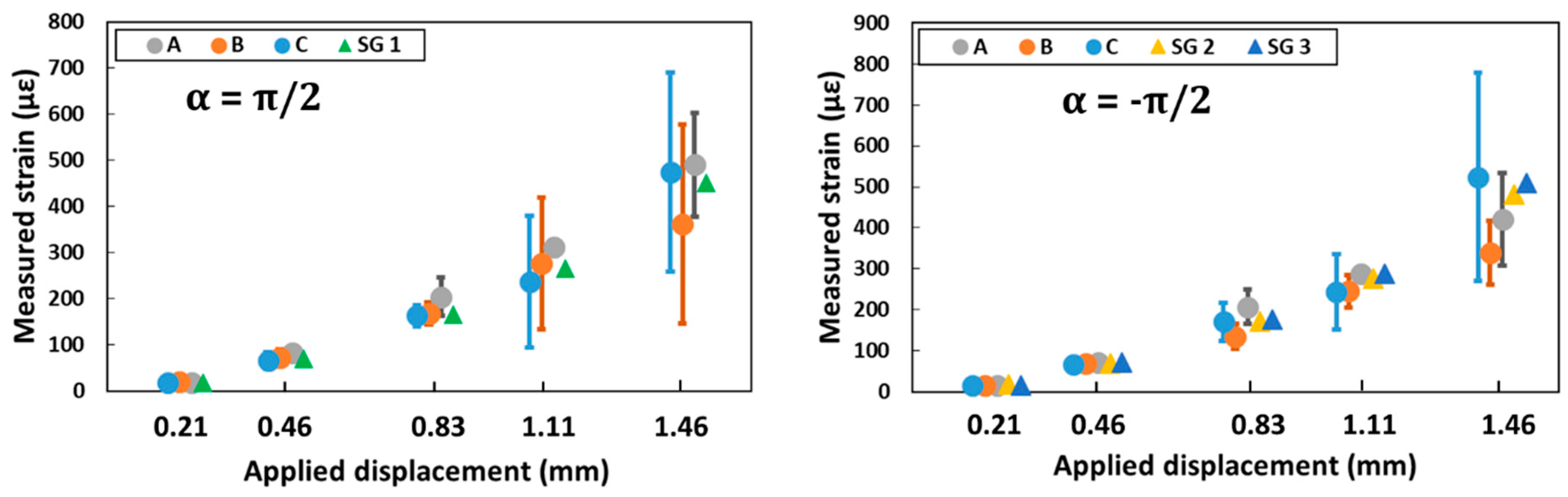
3.1.2. Comparison between DOFS and SG Measurements
3.1.3. Analysis of Strain Measurements
- -
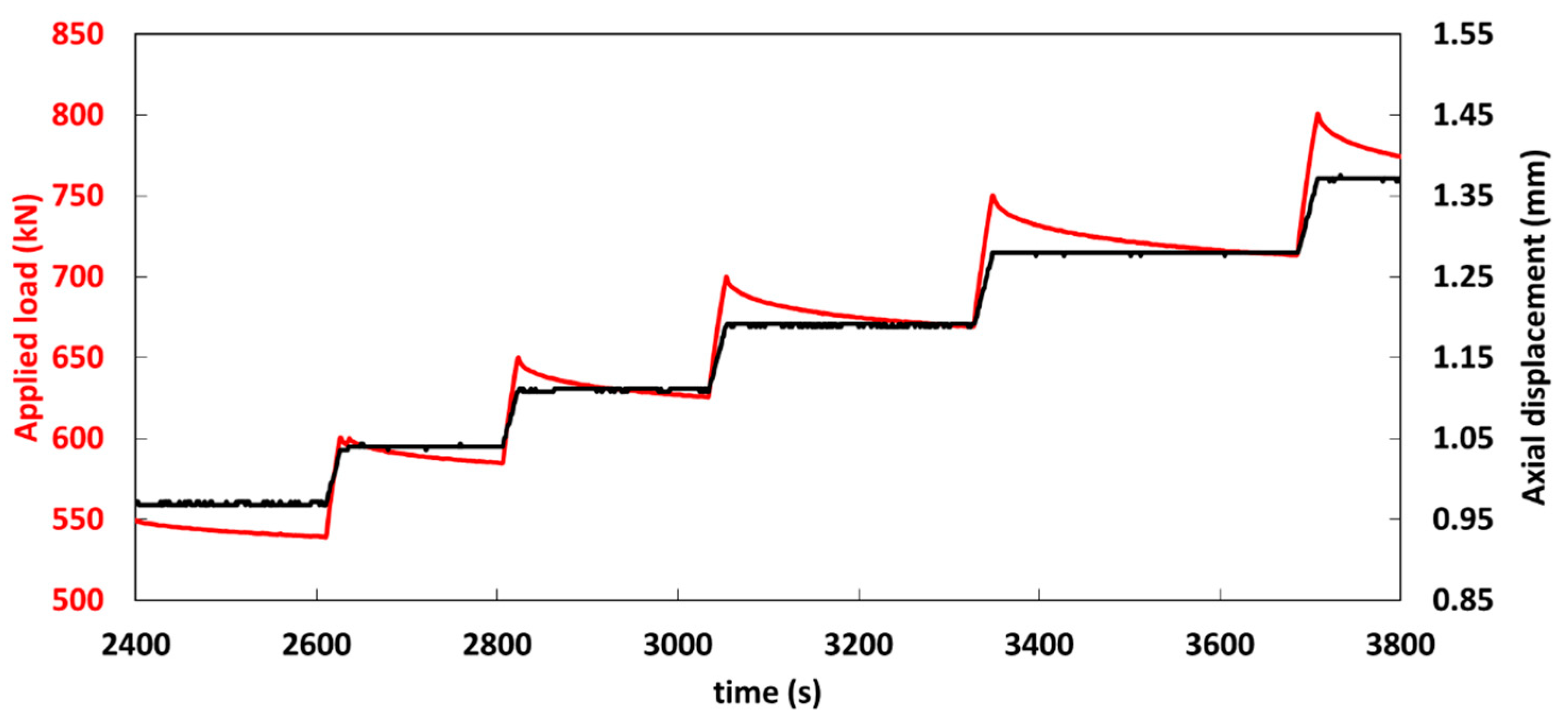
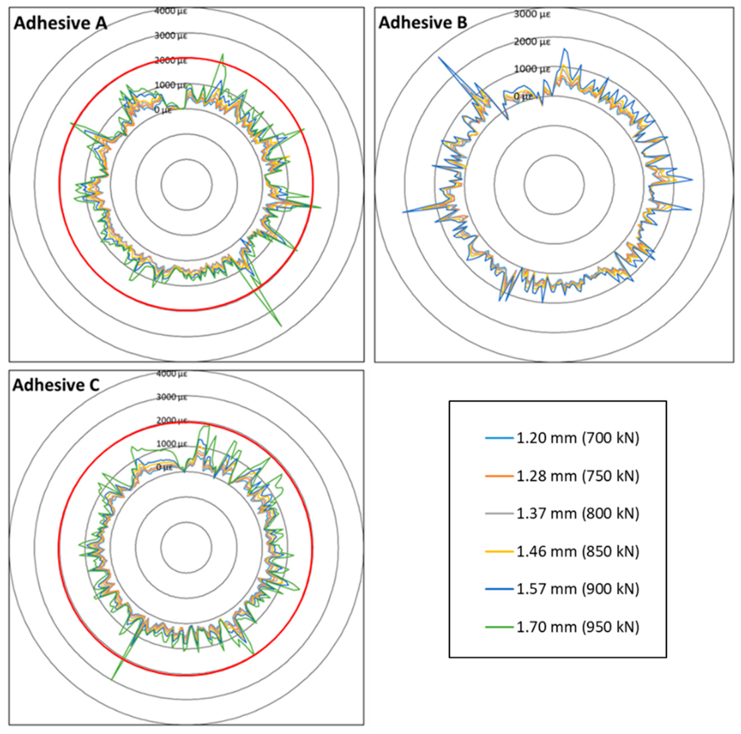
- For a given compression load level, the mean height of the strain peaks increases as the elastic modulus of the adhesive is raised. For example, at the load corresponding to an applied displacement of 1.70 mm, more peaks exceeding 2000 με (this strain level is identified by the red circle in Figure 10) are detected along the DOFS bonded with Adhesive A (6 peaks) compared to the sensor bonded with Adhesive C (only 2 peaks detected).
- -
- In addition, the width at half height of the peaks is much narrower in the case of the stiff polymer adhesive (Adhesive A) compared to softer one (Adhesive C).
3.2. Bending Test on a Notched Concrete Prism
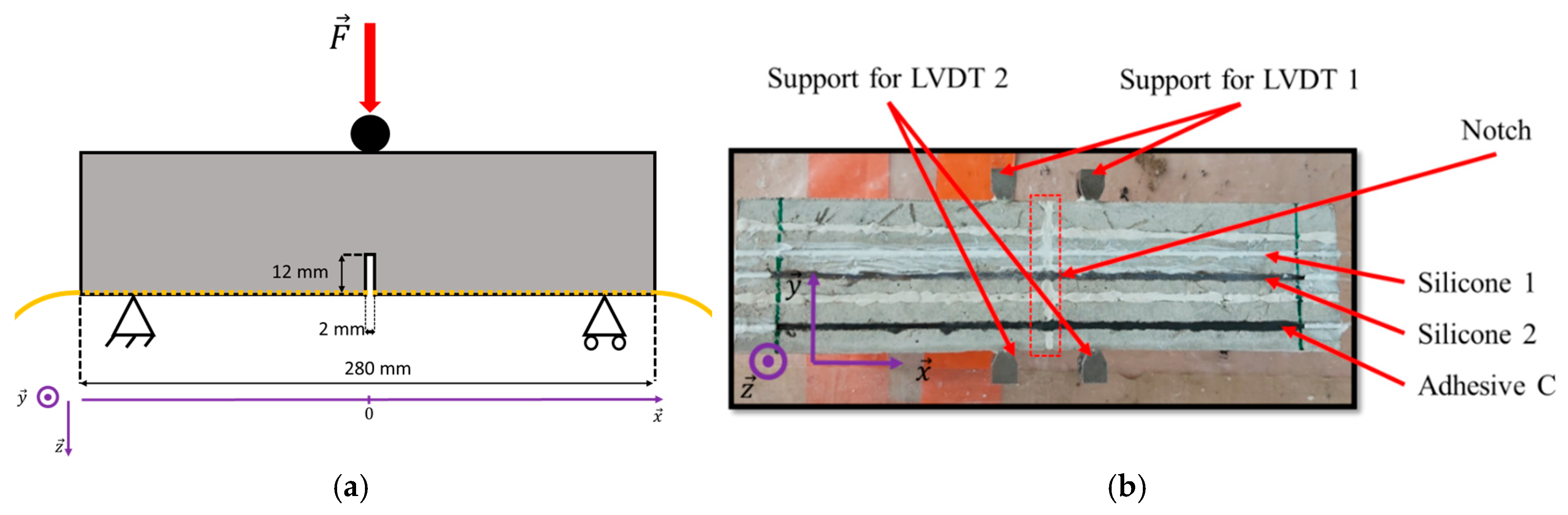
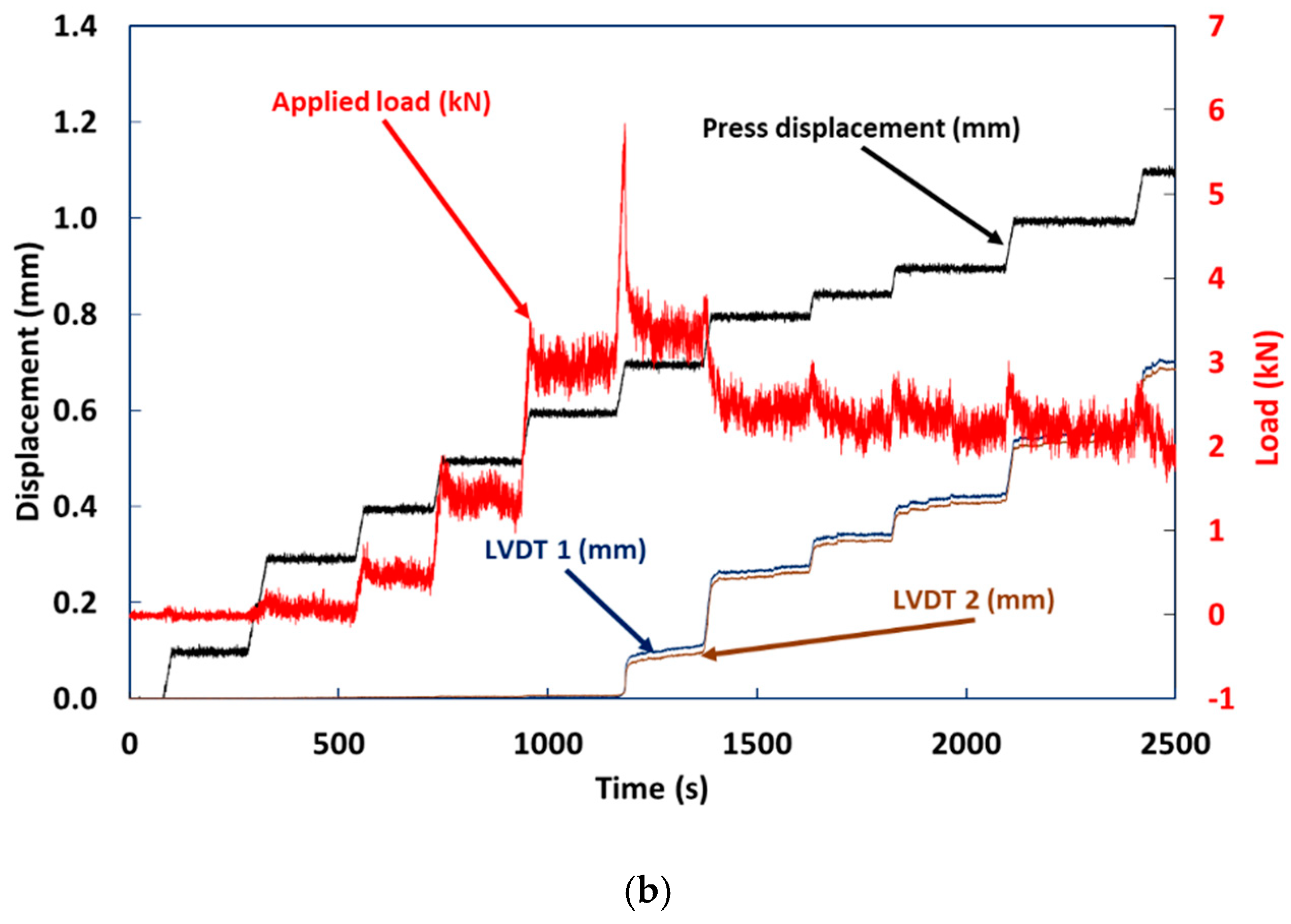
3.2.1. Test Procedure
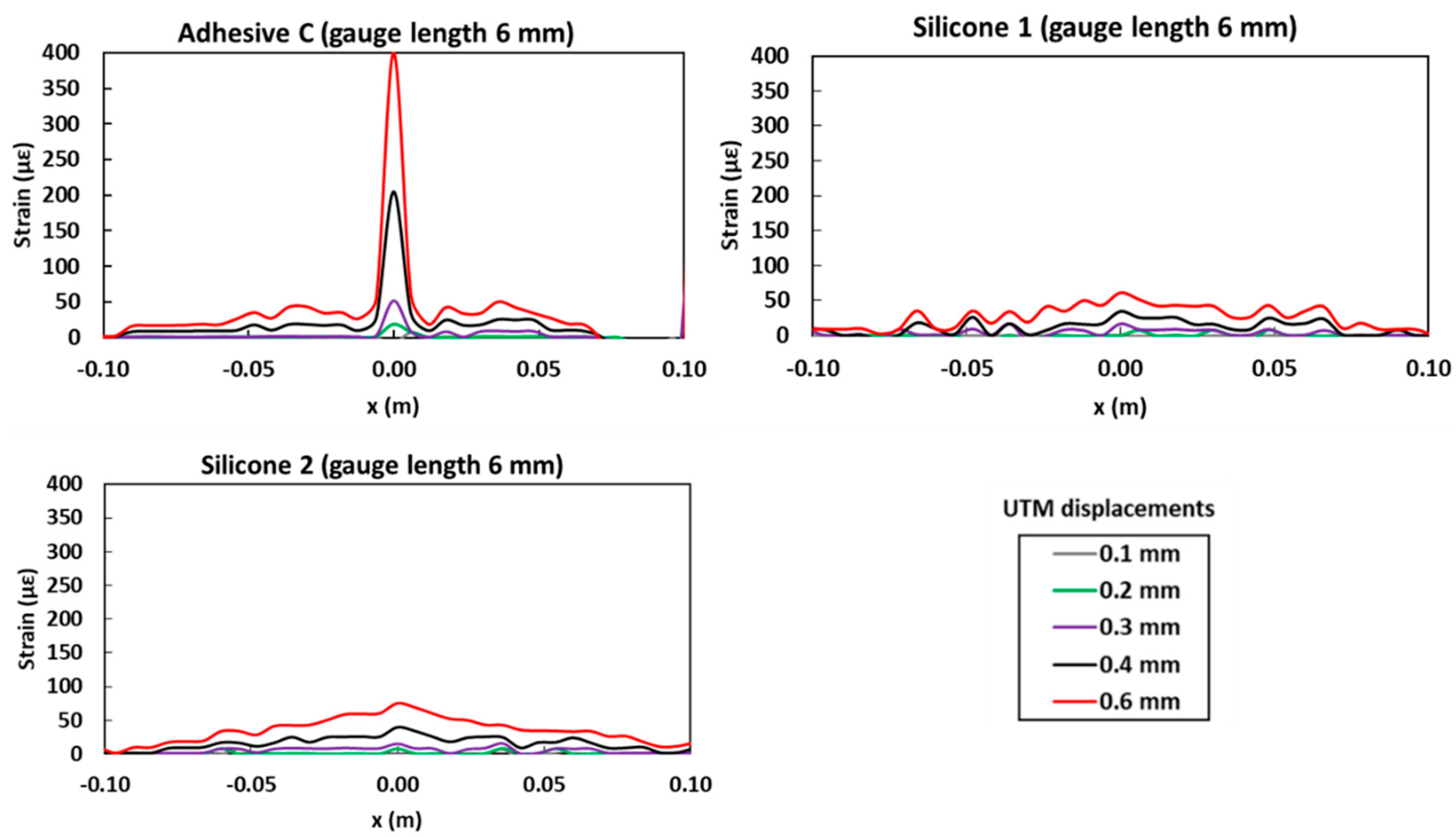
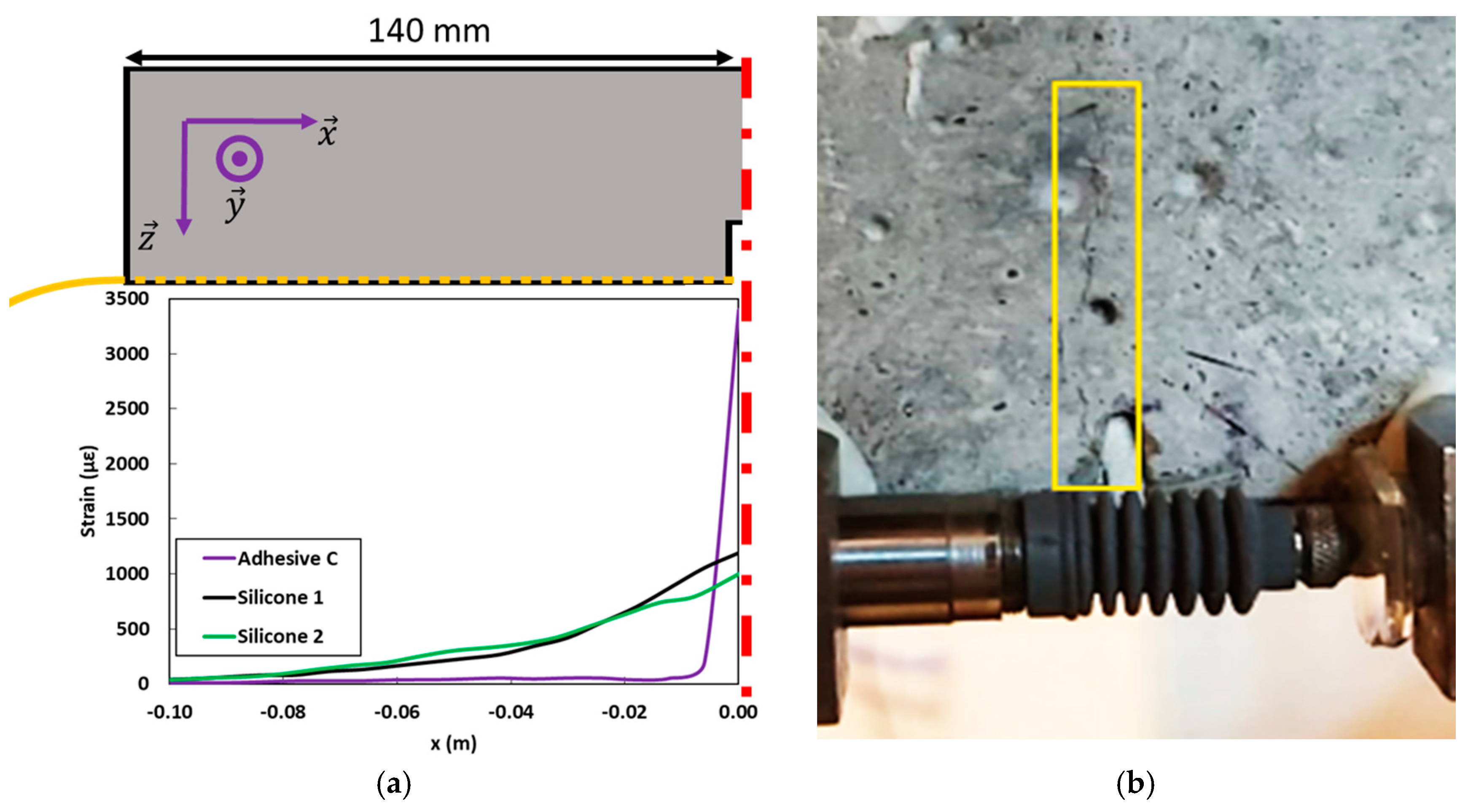
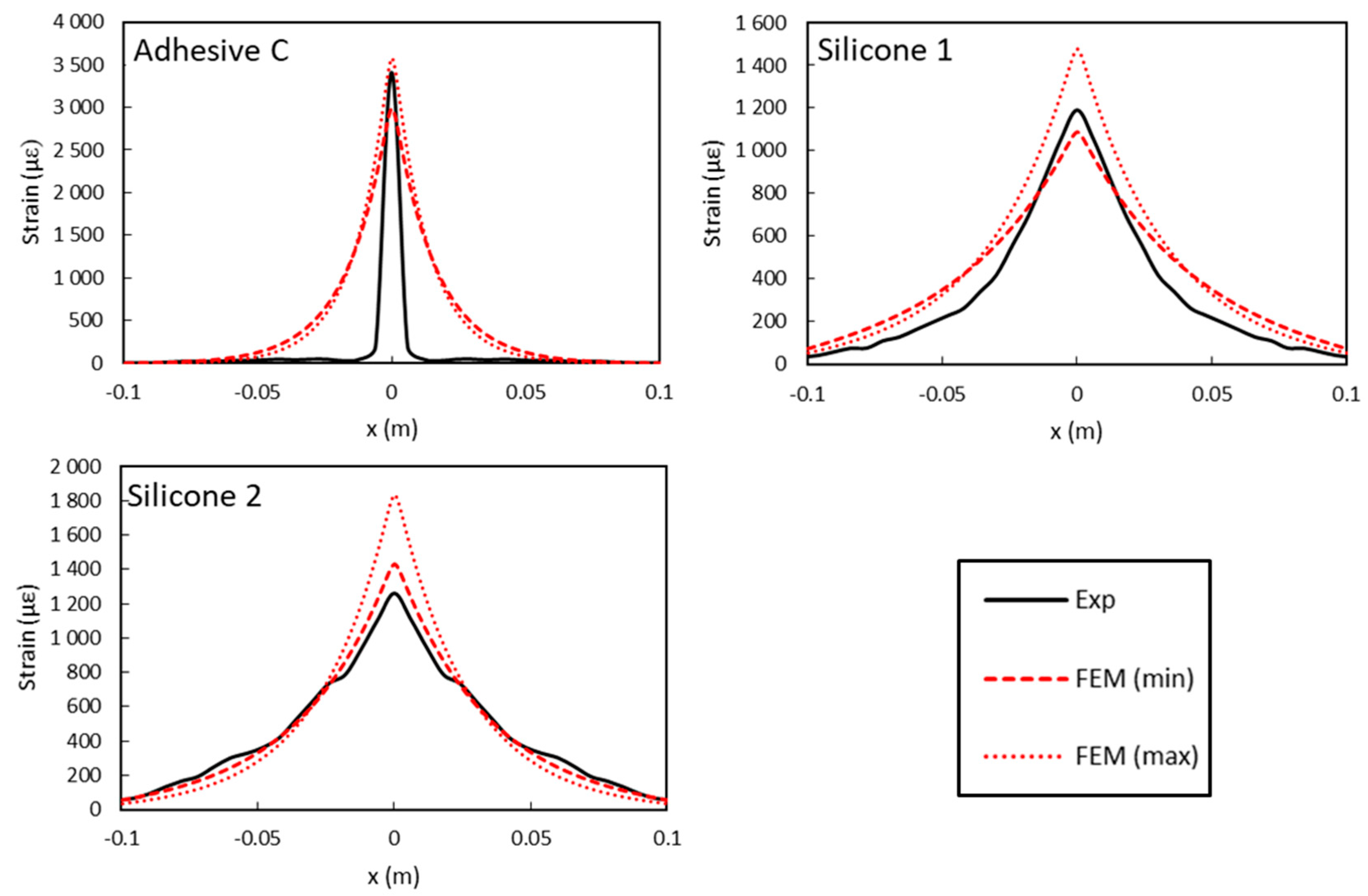
3.2.2. Analysis of DOFS Strain Profiles
4. Generalized Strain Transfer FEM Including the Effect of Crack Opening
4.1. Representative FEM Geometry
4.2. Validation of the Model: Simulation of the Bending Test
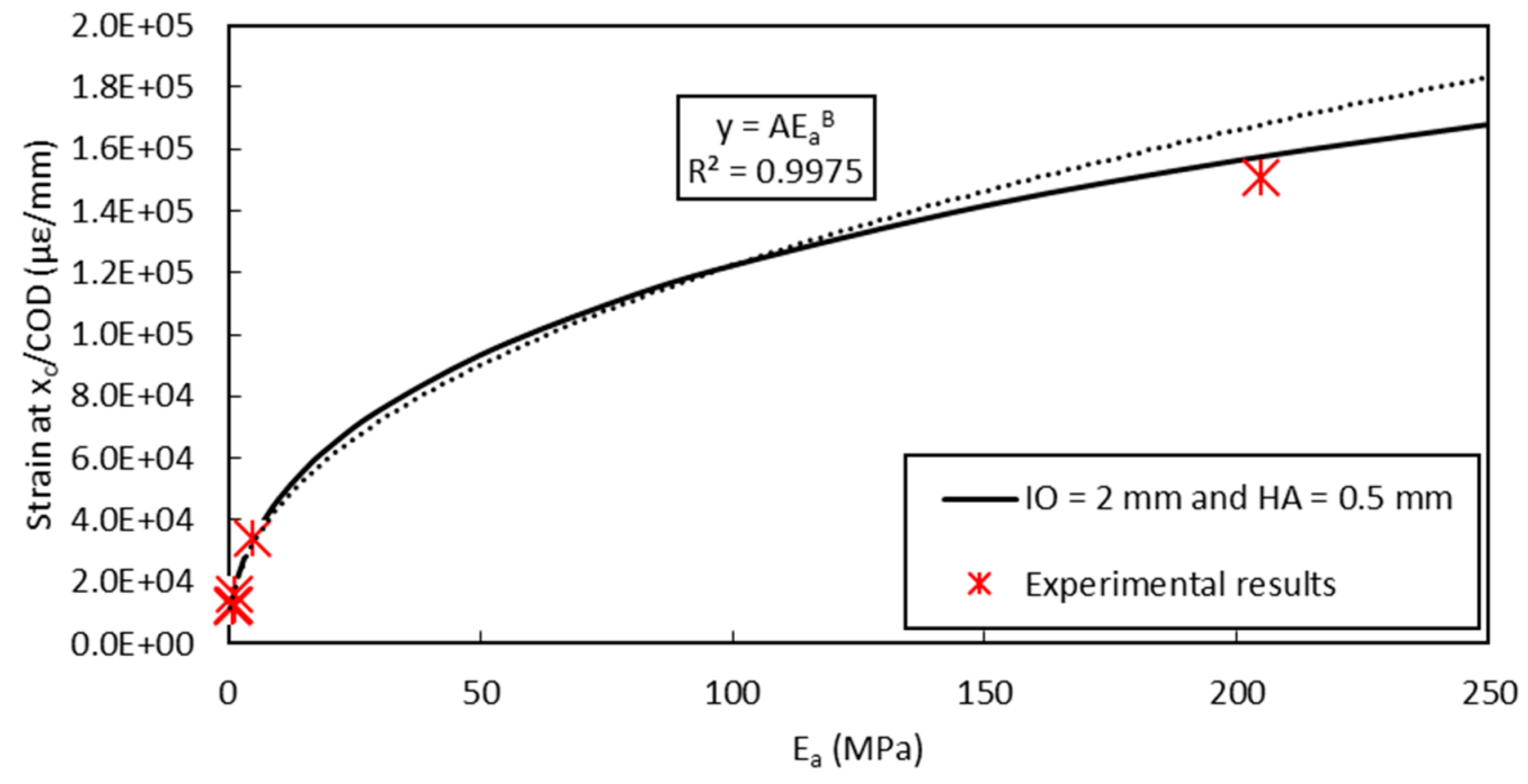
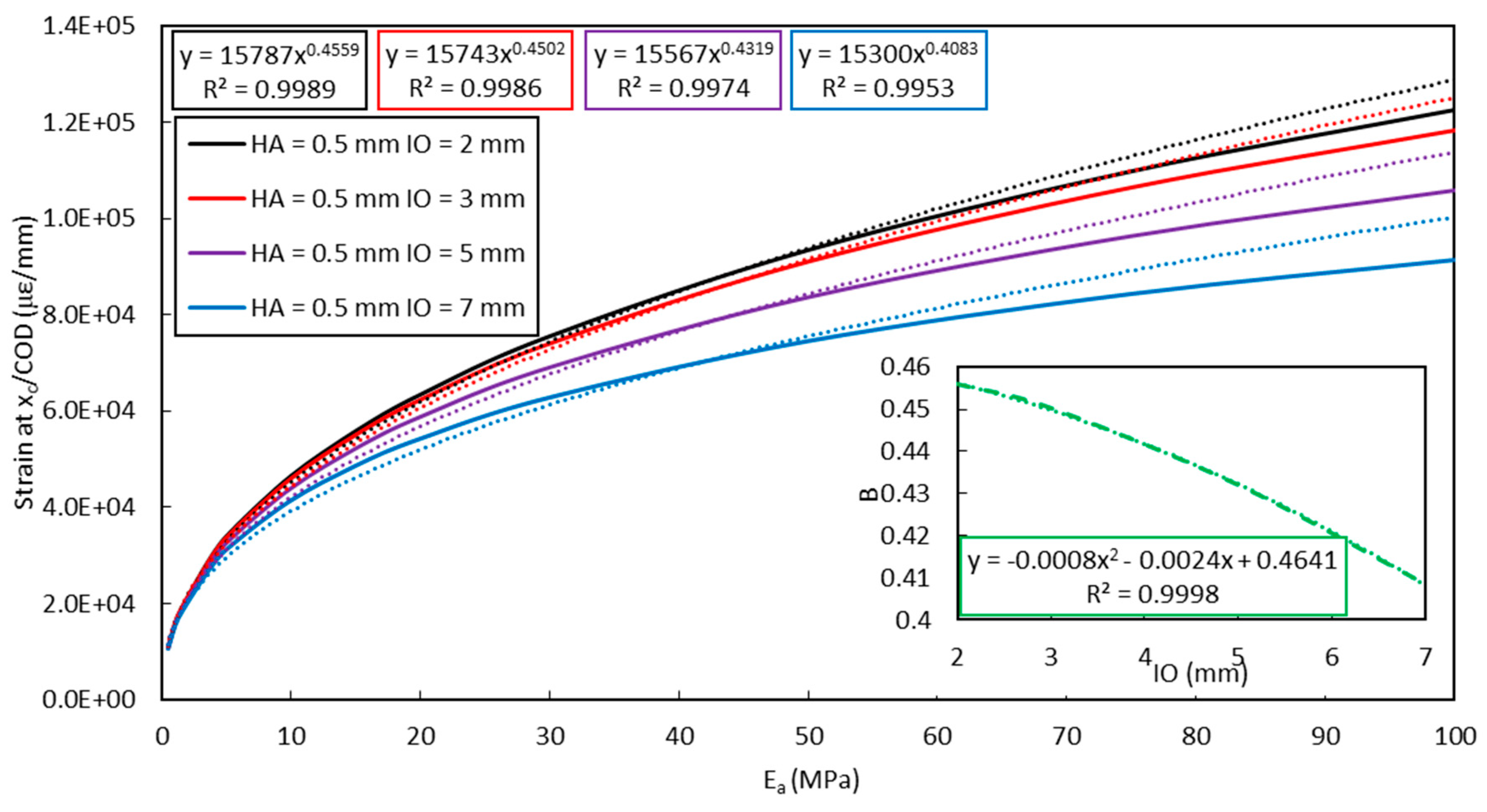
4.3. Application of the FEM to the Assessment of Crack Opening
5. Conclusions
Author Contributions
Funding
Conflicts of Interest
References
- Rodríguez, G.; Casas, J.R.; Villaba, S. Cracking assessment in concrete structures by distributed optical fiber. Smart Mater. Struct. 2015, 24, 35005. [Google Scholar] [CrossRef]
- Barrias, A.; Casas, J.R.; Villalba, S. Fatigue performance of distributed optical fiber sensors in reinforced concrete elements. Constr. Build. Mater. 2019, 218, 214–223. [Google Scholar] [CrossRef]
- Ye, X.W.; Su, Y.H.; Han, J.P. Structural health monitoring of civil infrastructure using optical fiber sensing technology: A comprehensive review. Sci. World J. 2014, 2014, 652329. [Google Scholar] [CrossRef] [PubMed]
- Bremer, K.; Wollweber, M.; Weigand, F.; Rahlves, M.; Kuhne, M.; Helbig, R.; Roth, B. Fibre Optic Sensors for the Structural Health Monitoring of Building Structures. Proced. Technol. 2016, 26, 524–529. [Google Scholar] [CrossRef]
- Weisbrich, M.; Holschemacher, K.; Bier, T. Comparison of different fiber coatings for distributed strain measurement in cementitious matrices. J. Sens. Sens. Syst. 2020, 9, 189–197. [Google Scholar] [CrossRef]
- Yao, Y.; Li, S.; Li, Z. Structural Cracks Detection Based on Distributed Weak FBG. In Proceedings of the 26th International Conference on Optical Fiber Sensors OSA, Lausanne, Switzerland, 24–28 September 2018; pp. 26–29. [Google Scholar]
- Billon, A.; Hénault, J.M.; Quiertant, M.; Taillade, F.; Khadour, A.; Martin, R.P.; Benzarti, K. Qualification of a distributed optical fiber sensor bonded to the surface of a concrete structure: A methodology to obtain quantitative strain measurements. Smart Mater. Struct. 2015, 24, 115001. [Google Scholar] [CrossRef]
- Khadour, A.; Waeytens, J. Monitoring of Concrete Structures with Optical Fiber Sensors. In Eco-Efficient Repair and Rehabilitation of Concrete Infrastructures; Woodhead Publishing: Cambridge, UK, 2018; pp. 97–121. [Google Scholar]
- Briançon, L.; Nancy, A.; Caquel, F.; Villard, P. New Technology for Strain Measurements in Soil and the Survey of Reinforced Earth Constructions. In Proceedings of the 3rd European Geosynthetics Conference, Munich, Germany, 1–3 March 2004; pp. 471–476. [Google Scholar]
- Habel, W.R.; Bismarck, A. Optimization of the adhesion of fiber-optic strain sensors embedded in cement matrices; a study into long-term fiber strength. J. Struct. Control 2000, 7, 51–76. [Google Scholar] [CrossRef]
- Loutas, T.H.; Charlaftis, P.; Airoldi, A.; Bettini, P.; Koimtzoglou, C.; Kostopoulos, V. Reliability of strain monitoring of composite structures via the use of optical fiber ribbon tapes for structural health monitoring purposes. Compos. Struct. 2015, 134, 762–771. [Google Scholar] [CrossRef]
- Zhang, Q.; Xiong, Z. Crack Detection of Reinforced Concrete Structures Based on BOFDA and FBG Sensors. Shock Vib. 2018, 2018, 6563537. [Google Scholar] [CrossRef]
- Imai, M.; Nakano, R.; Kono, T.; Ichinomiya, T.; Miura, S.; Mure, M. Crack Detection Application for Fiber Reinforced Concrete Using BOCDA-Based Optical Fiber Strain Sensor. J. Struct. Eng. 2010, 136, 1001–1008. [Google Scholar] [CrossRef]
- Gui, X.; Li, Z.; Fu, X.; Wang, C.; Wang, Y.; Li, H.; Wang, H. High-density distributed crack tip sensing system using dense ultra-short FBG sensors. Sensors 2019, 19, 1702. [Google Scholar] [CrossRef] [PubMed]
- Henault, J.M.; Quiertant, M.; Delepine-Lesoille, S.; Salin, J.; Moreau, G.; Taillade, F.; Benzarti, K. Quantitative strain measurement and crack detection in RC structures using a truly distributed fiber optic sensing system. Constr. Build. Mater. 2012, 37, 916–923. [Google Scholar] [CrossRef]
- Villalba, S.; Casas, J.R. Application of optical fiber distributed sensing to health monitoring of concrete structures. Mech. Syst. Signal Process. 2013, 39, 441–451. [Google Scholar] [CrossRef]
- Davis, M.; Hoult, N.A.; Scott, A. Distributed strain sensing to assess corroded RC beams. Eng. Struct. 2017, 140, 473–482. [Google Scholar] [CrossRef]
- Quiertant, M.; Baby, F.; Khadour, A.; Marchand, P.; Rivillon, P.; Toutlemonde, F.; Simon, A.; Cordier, J.; Billon, J.; Lapeyrer, R.; et al. Deformation Monitoring of Reinforcement Bars with a Distributed Fiber Optic Sensor for the SHM of Reinforced Concrete Structure. In Proceedings of the 9th International Conference on NDE in Relation to Structural Integrity for Nuclear and Pressurized Components, Seattle, WA, USA, 22–24 May 2012. [Google Scholar]
- Rolland, A.; Argoul, P.; Benzarti, K.; Quiertant, M.; Chataigner, S.; Khadour, A. Analytical and numerical modeling of the bond behavior between FRP reinforcing bars and concrete. Constr. Build. Mater. 2020, 20, 117160. [Google Scholar] [CrossRef]
- Alj, I.; Quiertant, M.; Khadour, A.; Grando, Q.; Benzarti, K. Durability of Distributed Optical Fiber Sensors used for SHM of Reinforced Concrete Structures. In Proceedings of the IWSHM 2019 The 12th International Workshop on Structural Health Monitoring, Stanford, CA, USA, 10–12 September 2019; pp. 1732–1740. [Google Scholar]
- Hénault, J.-M. Approche Méthodologique pour l’évaluation des Performances et de la Durabilité des Systèmes de Mesure Réparties De Déformation: Application à un câble à fibre optique noyé dans le béton; Université Paris-Est: Champs-sur-Marne, France, 2013. [Google Scholar]
- Henault, J.M.; Salin, J.; Moreau, G.; Quiertant, M.; Taillade, F.; Benzarti, K.; Delepine-Lesoille, S. Analysis of the Strain Transfer Mechanism between a Truly Distributed Optical Fiber Sensor and the Surrounding Medium. In Proceedings of the the 3rd International Conference on Concrete Repair, Rehabilitation and Retrofitting, ICCRRR 2012, Cap Town, South Africa, 3–5 September 2012; pp. 733–739. [Google Scholar]
- Hénault, J.; Quiertant, M.; Salin, J.; Moreau, G.; Delepine-Lesoille, S.; Benzarti, K. Mesures réparties de déformation par fibre optique. Évaluation des performances d’un système de mesure en conditions d’emploi contrôlées en vue d’applications de surveillance d’ouvrages de génie civil en béton. IEEE Instrum. Mes. Metrol. 2013, 13, 97–130. [Google Scholar] [CrossRef]
- Billon, A.; Henault, J.; Quiertant, M.; Taillade, F.; Khadour, A.; Martin, R.; Benzarti, K. Quantitative Strain Measurement with Distributed Fiber Optic Systems: Qualification of a Sensing Cable Bonded to the Surface of a Concrete Structure. In Proceedings of the 7th European Workshop on Structural Health Monitoring, Nantes, France, 8–11 July 2014. [Google Scholar]
- Falcetelli, F.; Rossi, L.; Di Sante, R.; Bolognini, G. Strain Transfer in Surface-Bonded Optical Fiber Sensors. Sensors 2020, 20, 3100. [Google Scholar] [CrossRef]
- Her, S.; Huang, C. Thermal Strain Analysis of Optic Fiber Sensors. Sensors 2013, 13, 1846–1855. [Google Scholar] [CrossRef]
- Lammens, N.; Luyckx, G.; Geernaert, T.; Kinet, D.; Berghmans, F.; Caucheteur, C.; Degrieck, J. Importance of Strain Transfer Effects for Embedded Multiaxial Strain Sensing and Optical Fiber Coating Optimization. Structural Health Monitoring of Composite Structures Using Fiber Optic Methods; Taylor & Francis Group: Oxfordshire, UK, 2016; pp. 157–199. [Google Scholar]
- Glisic, B.; Inaudi, D. Development of method for in-service crack detection based on distributed fiber optic sensors. Struct. Health Monit. 2011, 11, 161–171. [Google Scholar] [CrossRef]
- Barrias, A.; Casas, J.R.; Villalba, S. Distributed optical fibre sensors in concrete structures: Performance of bonding adhesives and influence of spatial resolution. Struct. Control Health Monit. 2019, 26, 1–16. [Google Scholar]
- Cast3m Software. Available online: http://www-cast3m.cea.fr (accessed on 1 December 2018).
- Kim, S.W.; Jeong, M.S.; Lee, I.; Kim, E.H.; Kwon, I.B.; Hwang, T.K. Determination of the maximum strains experienced by composite structures using metal coated optical fiber sensors. Compos. Sci. Technol. 2013, 78, 48–55. [Google Scholar] [CrossRef]
- Her, S.C.; Huang, C.Y. Effect of coating on the strain transfer of optical fiber sensors. Sensors 2011, 11, 6926–6941. [Google Scholar] [CrossRef] [PubMed]
- Zhou, J.; Zhou, Z.; Zhang, D. Study on strain transfer characteristics of fiber Bragg grating sensors. J. Intell. Mater. Syst. Struct. 2010, 21, 1117–1122. [Google Scholar] [CrossRef]
- AFNOR Standard NF EN ISO 527-2 Plastics—Determination of Tensile Properties—Part 2: Test Conditions for Moulding and Extrusion Plastics. 2012. Available online: https://standards.globalspec.com/std/1534984/nf-en-iso-527-2 (accessed on 23 October 2019).
- AFNOR Standard NF EN 14651 Test Method for Metallic Fibered Concrete—Measuring the Flexural Tensile Strength (Limit or Proportionality (LOP), Residual). 2007. Available online: https://standards.globalspec.com/std/1084005/NF%20EN%2014651+A1 (accessed on 12 June 2019).
- Feng, X.; Zhou, J.; Sun, C.; Zhang, X.; Ansari, F. Theoretical and experimental investigations into crack detection with BOTDR-distributed fiber optic sensors. J. Eng. Mech. 2013, 139, 1797–1807. [Google Scholar] [CrossRef]
- Ansari, F.; Libo, Y. Mechanics of Bond and Interface Shear Transfer in Optical Fiber Sensors. J. Eng. Mech. 1998, 124, 385–394. [Google Scholar] [CrossRef]
- Li, H.; Zhou, G.; Ren, L.; Li, D. Strain Transfer Coefficient Analyses for Embedded Fiber Bragg Grating Sensors in Different Host Materials. J. Eng. Mech. 2009, 135, 1343–1354. [Google Scholar] [CrossRef]
- Wang, H.; Zhou, Z. Advances of strain transfer analysis of optical fibre sensors. Pac. Sci. Rev. 2014, 16, 8–18. [Google Scholar] [CrossRef]
- Imai, M.; Feng, M. Sensing optical fiber installation study for crack identification using a stimulated Brillouin-based strain sensor. Struct. Health Monit. 2012, 11, 501–509. [Google Scholar] [CrossRef]
- Duck, G.; LeBlanc, M. Arbitrary strain transfer from a host to an embedded fiber-optic sensor. Smart Mater. Struct. 2000, 9, 492. [Google Scholar] [CrossRef]
- Bassil, A.; Wang, X.; Chapeleau, X.; Niederleithinger, E.; Abraham, O.; Leduc, D. Distributed fiber optics sensing and coda wave interferometry techniques for damage monitoring in concrete structures. Sensors 2019, 19, 356. [Google Scholar] [CrossRef]
- Bassil, A.; Chapeleau, X.; Leduc, D.; Abraham, O. Concrete crack monitoring using a novel strain transfer model for distributed fiber optics sensors. Sensors 2020, 20, 2220. [Google Scholar] [CrossRef] [PubMed]


| Designation | Notation | Values Used in This Study |
|---|---|---|
| Radius of DOFS core | rf | 0.06 mm |
| External radius of the DOFS | rc | 0.08 mm |
| Length of the concrete block | Lb | 6 mm |
| Height of host material (concrete) below the DOFS | 10 mm | |
| Young’s modulus of DOFS core | 72 GPa | |
| Poisson’s ratio of DOFS core | - | 0.17 |
| Young’s modulus of PI coating | 3 GPa | |
| Poisson’s ratio of the PI coating | - | 0.4 |
| Shear modulus of the PI coating | 1.43 GPa | |
| Young’s modulus of the polymer adhesive | Variable (10, 100, and 1000 MPa) | |
| Poisson’s ratio of the polymer adhesive | - | 0.48 |
| Shear modulus of the polymer adhesive | Variable (depending on ) | |
| Young’s modulus of the host material (concrete) | 30 GPa | |
| Poisson’s ratio of concrete | - | 0.2 |
| Designation | Type of Adhesive | Young’s Modulus (MPa) | Standard Deviation (MPa) |
|---|---|---|---|
| Adhesive A | Bi-component epoxy system used in construction (highly thixotropic paste) | 11,200 1 | - |
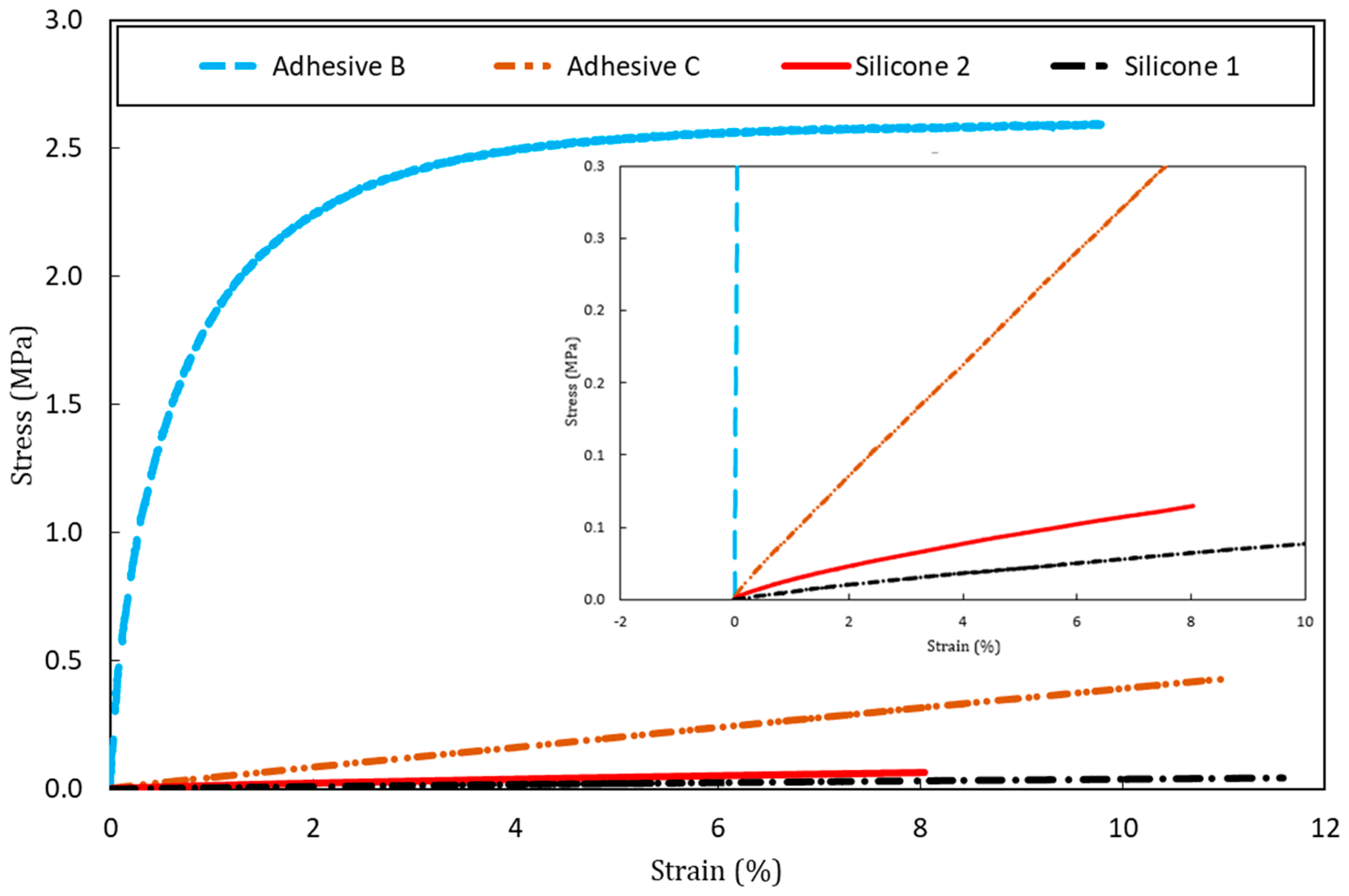
| Adhesive B | Bi-component epoxy system suitable for bonding variety of materials (high viscosity liquid adhesive) | 205 | 5 |
| Adhesive C | Bi-component epoxy system suitable for bonding wide variety of materials (fast cure adhesive) | 4.8 | 1.3 |
| Silicone 1 | Mastic silicone used for sealing and bonding applications | 0.7 | 0.3 |
| Silicone 2 | Silicone rubber used to protect strain-gauge installations | 1.1 | 0.4 |
© 2020 by the authors. Licensee MDPI, Basel, Switzerland. This article is an open access article distributed under the terms and conditions of the Creative Commons Attribution (CC BY) license (http://creativecommons.org/licenses/by/4.0/).
Share and Cite
Alj, I.; Quiertant, M.; Khadour, A.; Grando, Q.; Terrade, B.; Renaud, J.-C.; Benzarti, K. Experimental and Numerical Investigation on the Strain Response of Distributed Optical Fiber Sensors Bonded to Concrete: Influence of the Adhesive Stiffness on Crack Monitoring Performance. Sensors 2020, 20, 5144. https://doi.org/10.3390/s20185144
Alj I, Quiertant M, Khadour A, Grando Q, Terrade B, Renaud J-C, Benzarti K. Experimental and Numerical Investigation on the Strain Response of Distributed Optical Fiber Sensors Bonded to Concrete: Influence of the Adhesive Stiffness on Crack Monitoring Performance. Sensors. 2020; 20(18):5144. https://doi.org/10.3390/s20185144
Chicago/Turabian StyleAlj, Ismail, Marc Quiertant, Aghiad Khadour, Quentin Grando, Benjamin Terrade, Jean-Claude Renaud, and Karim Benzarti. 2020. "Experimental and Numerical Investigation on the Strain Response of Distributed Optical Fiber Sensors Bonded to Concrete: Influence of the Adhesive Stiffness on Crack Monitoring Performance" Sensors 20, no. 18: 5144. https://doi.org/10.3390/s20185144
APA StyleAlj, I., Quiertant, M., Khadour, A., Grando, Q., Terrade, B., Renaud, J.-C., & Benzarti, K. (2020). Experimental and Numerical Investigation on the Strain Response of Distributed Optical Fiber Sensors Bonded to Concrete: Influence of the Adhesive Stiffness on Crack Monitoring Performance. Sensors, 20(18), 5144. https://doi.org/10.3390/s20185144