Insulator Based Dielectrophoresis: Micro, Nano, and Molecular Scale Biological Applications


Abstract
1. Introduction
2. Theory
3. Discussion
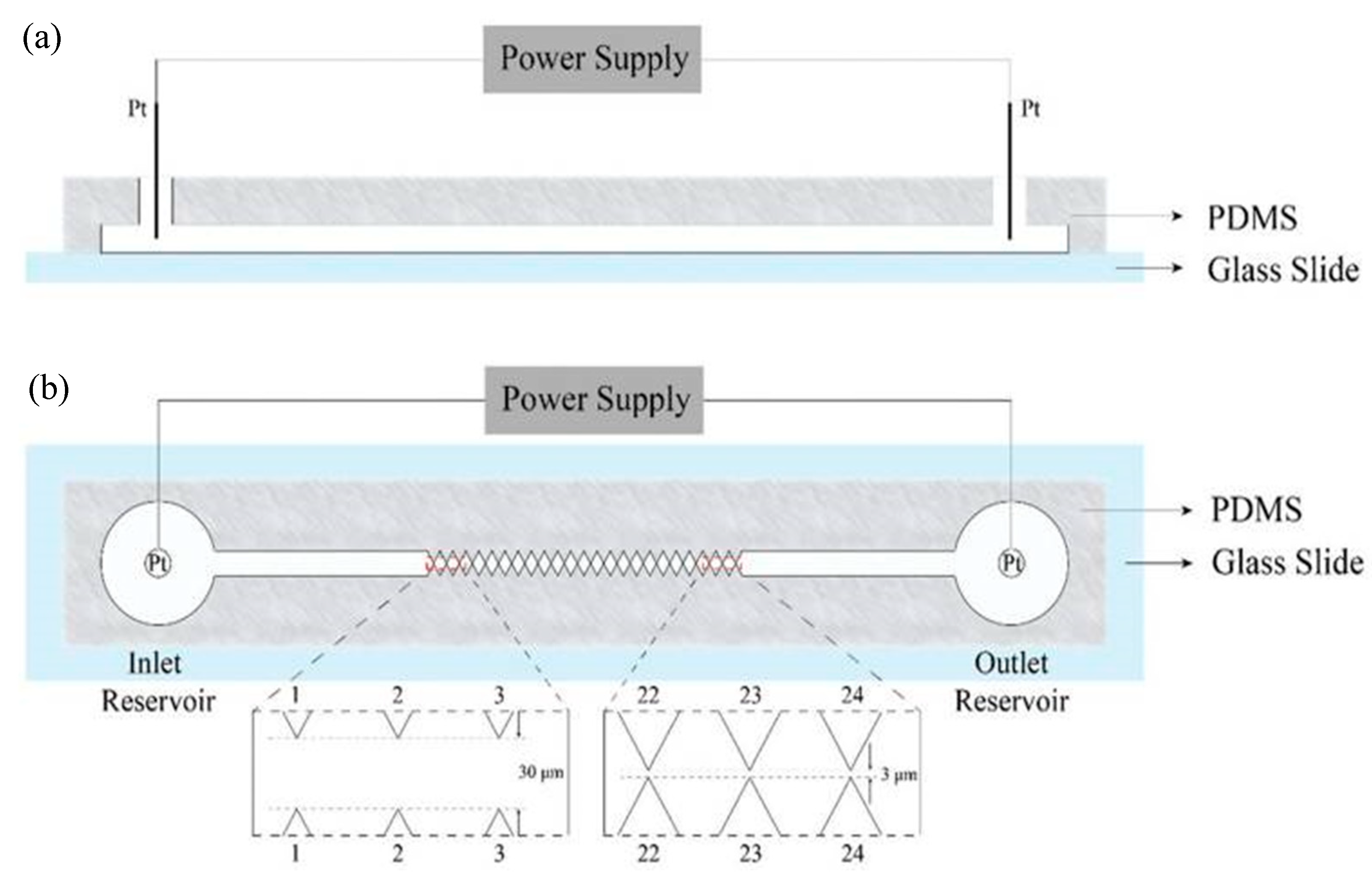
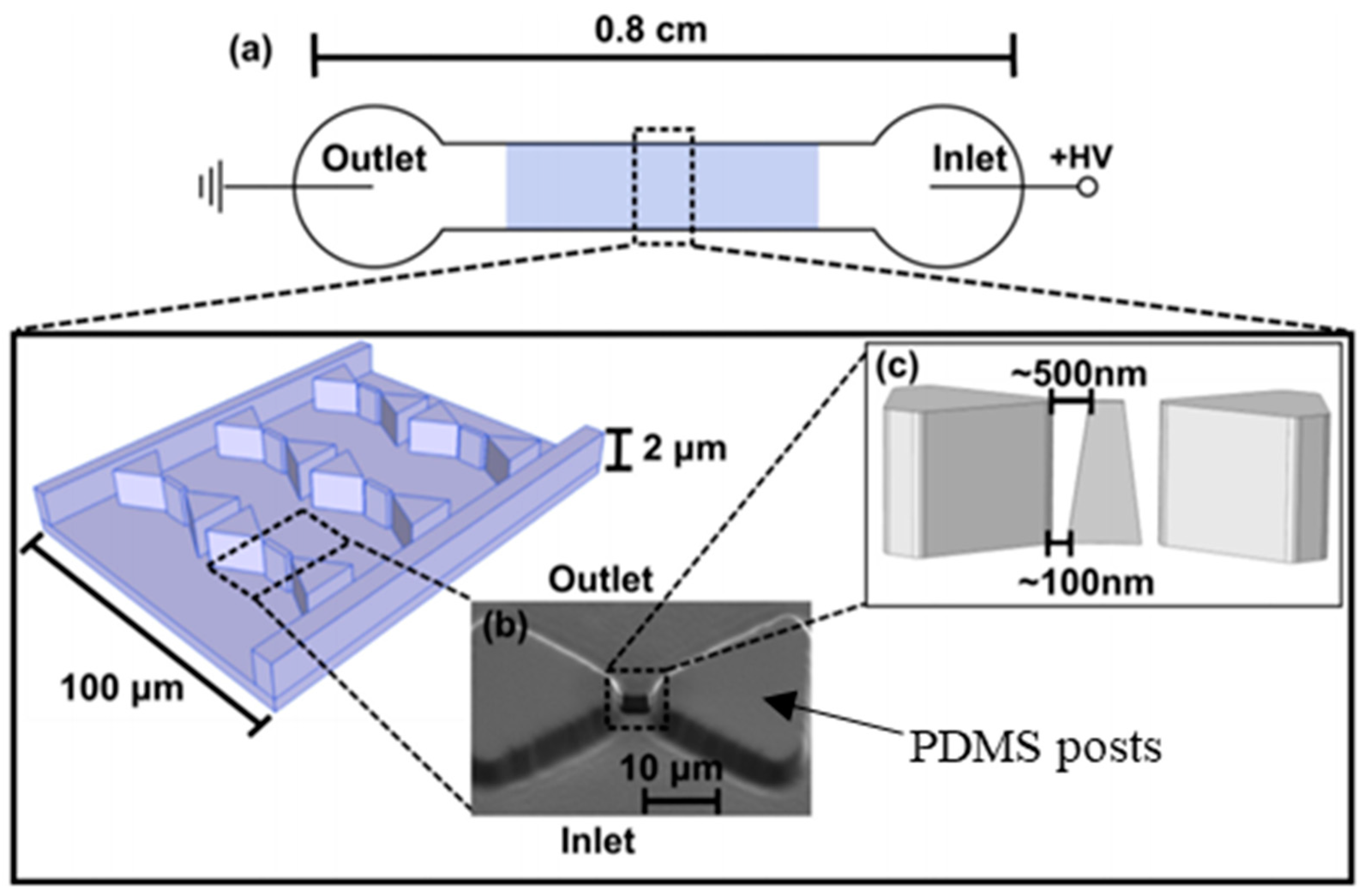
3.1. Cells
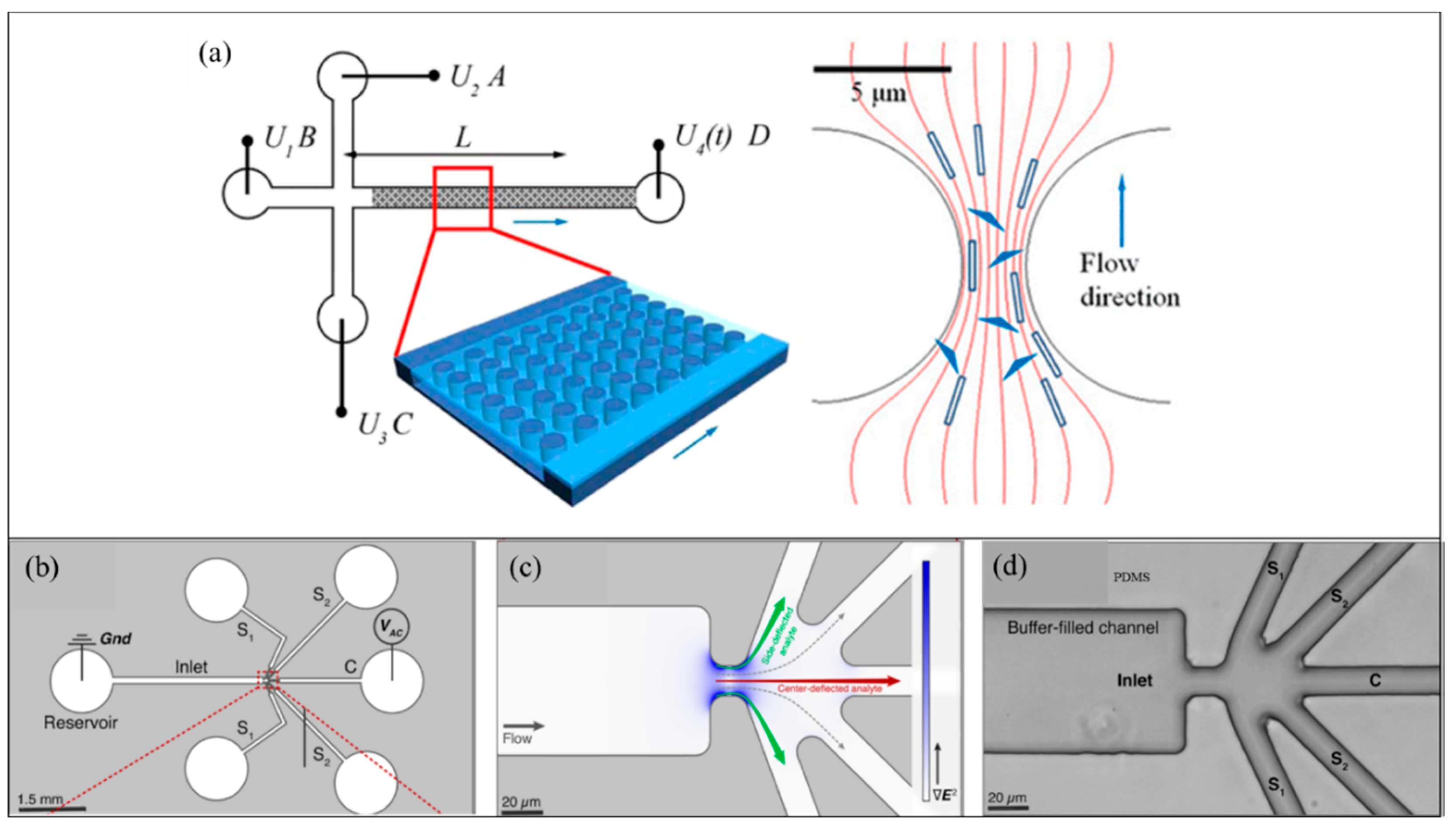
3.2. Viruses and Extracellular Vesicles
3.3. Proteins
3.4. Nucleic Acids
4. Knowledge Gaps and Future Directions
4.1. Overcoming Effects of High Electric Field and Gradients
4.2. Optimization of Fluid Micro-Environments
5. Conclusions
Supplementary Materials
Author Contributions
Funding
Acknowledgments
Conflicts of Interest
References
- Pohl, H.A. The Motion and Precipitation of Suspensoids in Divergent Electric Fields. J. Appl. Phys. 1951, 22, 869–871. [Google Scholar] [CrossRef]
- Bazant, M.Z. Induced-Charge Electrokinetic Phenomena. In Electrokinetics and Electrohydrodynamics in Microsystems; Ramos, A., Ed.; Springer: Vienna, Austria, 2011; pp. 221–297. [Google Scholar] [CrossRef]
- Yariv, E. “Force-free” electrophoresis? Phys. Fluids 2006, 18, 031702. [Google Scholar] [CrossRef]
- Liu, W.; Ren, Y.; Tao, Y.; Zhou, Z.; Wu, Q.; Xue, R.; Yao, B. Multiple frequency electrothermal induced flow: Theory and microfluidic applications. J. Phys. D Appl. Phys. 2020, 53, 175304. [Google Scholar] [CrossRef]
- Gao, J.; Sin, M.L.Y.; Liu, T.; Gau, V.; Liao, J.C.; Wong, P.K. Hybrid electrokinetic manipulation in high-conductivity media. Lab. A Chip 2011, 11, 1770–1775. [Google Scholar] [CrossRef]
- Wu, Y.; Ren, Y.; Tao, Y.; Hou, L.; Jiang, H. High-Throughput Separation, Trapping, and Manipulation of Single Cells and Particles by Combined Dielectrophoresis at a Bipolar Electrode Array. Anal. Chem. 2018, 90, 11461–11469. [Google Scholar] [CrossRef]
- Buyong, M.R.; Kayani, A.A.; Hamzah, A.A.; Yeop Majlis, B. Dielectrophoresis Manipulation: Versatile Lateral and Vertical Mechanisms. Biosensors 2019, 9, 30. [Google Scholar] [CrossRef]
- Pesch, G.R.; Lorenz, M.; Sachdev, S.; Salameh, S.; Du, F.; Baune, M.; Boukany, P.E.; Thöming, J. Bridging the scales in high-throughput dielectrophoretic (bio-)particle separation in porous media. Sci. Rep. 2018, 8, 10480. [Google Scholar] [CrossRef]
- Jiang, A.Y.L.; Yale, A.R.; Aghaamoo, M.; Lee, D.-H.; Lee, A.P.; Adams, T.N.G.; Flanagan, L.A. High-throughput continuous dielectrophoretic separation of neural stem cells. Biomicrofluidics 2019, 13, 064111. [Google Scholar] [CrossRef]
- Abd Rahman, N.; Ibrahim, F.; Yafouz, B. Dielectrophoresis for Biomedical Sciences Applications: A Review. Sensors 2017, 17, 449. [Google Scholar] [CrossRef]
- Mahshid, S.; Lu, J.; Abidi, A.A.; Sladek, R.; Reisner, W.W.; Ahamed, M.J. Transverse dielectrophoretic-based DNA nanoscale confinement. Sci. Rep. 2018, 8, 5981. [Google Scholar] [CrossRef]
- Rezaei Nejad, H.; Hoorfar, M. Purification of a droplet using negative dielectrophoresis traps in digital microfluidics. Microfluid. Nanofluid. 2015, 18, 483–492. [Google Scholar] [CrossRef]
- Soltanian-Zadeh, S.; Kikkeri, K.; Shajahan-Haq, A.N.; Strobl, J.; Clarke, R.; Agah, M. Breast cancer cell obatoclax response characterization using passivated-electrode insulator-based dielectrophoresis. Electrophoresis 2017, 38, 1988–1995. [Google Scholar] [CrossRef] [PubMed]
- Kim, Y.; Ren, X.; Kim, J.W.; Noh, H. Direct inkjet printing of micro-scale silver electrodes on polydimethylsiloxane (PDMS) microchip. J. Micromech. Microeng. 2014, 24, 115010. [Google Scholar] [CrossRef]
- Han, C.-H.; Ha, H.W.; Jang, J. Two-dimensional computational method for generating planar electrode patterns with enhanced volumetric electric fields and its application to continuous dielectrophoretic bacterial capture. Lab. A Chip 2019, 19, 1772–1782. [Google Scholar] [CrossRef] [PubMed]
- Wu, C.; Chen, R.; Liu, Y.; Yu, Z.; Jiang, Y.; Cheng, X. A planar dielectrophoresis-based chip for high-throughput cell pairing. Lab. A Chip 2017, 17, 4008–4014. [Google Scholar] [CrossRef]
- Cheng, I.F.; Chen, T.-Y.; Lu, R.-J.; Wu, H.-W. Rapid identification of bacteria utilizing amplified dielectrophoretic force-assisted nanoparticle-induced surface-enhanced Raman spectroscopy. Nanoscale Res. Lett 2014, 9, 324. [Google Scholar] [CrossRef]
- Nakano, A.; Ros, A. Protein dielectrophoresis: Advances, challenges, and applications. Electrophoresis 2013, 34, 1085–1096. [Google Scholar] [CrossRef]
- Zouaghi, A.; Zouzou, N.; Dascalescu, L. Effect of travelling wave electric field on fine particles motion on an electrodynamic board. In Proceedings of the 2017 IEEE Industry Applications Society Annual Meeting, Baltimore, OH, USA, 1–5 October 2017; pp. 1–6. [Google Scholar]
- Pethig, R.; Talary, M.S.; Lee, R.S. Enhancing traveling-wave dielectrophoresis with signal superposition. IEEE Eng. Med. Biol. Mag. 2003, 22, 43–50. [Google Scholar] [CrossRef]
- Ivanoff, C.S.; Wu, J.J.; Mirzajani, H.; Cheng, C.; Yuan, Q.; Kevorkyan, S.; Gaydarova, R.; Tomlekova, D. AC electrokinetic drug delivery in dentistry using an interdigitated electrode assembly powered by inductive coupling. Biomed. Microdevices 2016, 18, 84. [Google Scholar] [CrossRef]
- Tada, S.; Hayashi, M.; Eguchi, M.; Tsukamoto, A. High-throughput separation of cells by dielectrophoresis enhanced with 3D gradient AC electric field. Biomicrofluidics 2017, 11, 064110. [Google Scholar] [CrossRef]
- Thomas, R.S.W.; Mitchell, P.D.; Oreffo, R.O.C.; Morgan, H.; Green, N.G. Image-based sorting and negative dielectrophoresis for high purity cell and particle separation. Electrophoresis 2019, 40, 2718–2727. [Google Scholar] [CrossRef]
- Nakano, A.; Chao, T.C.; Camacho-Alanis, F.; Ros, A. Immunoglobulin G and bovine serum albumin streaming dielectrophoresis in a microfluidic device. Electrophoresis 2011, 32, 2314–2322. [Google Scholar] [CrossRef] [PubMed]
- Tada, S.; Eguchi, M.; Okano, K. Insulator-based dielectrophoresis combined with the isomotive AC electric field and applied to single cell analysis. Electrophoresis 2019, 40, 1494–1497. [Google Scholar] [CrossRef] [PubMed]
- Pethig, R. Dielectrophoresis: Theory, Methodology and Biological Applications, 1st ed.; John Wiley & Sons, Ltd.: Hoboken, NJ, USA, 2017; pp. 1–428. [Google Scholar] [CrossRef]
- Kwak, T.J.; Hossen, I.; Bashir, R.; Chang, W.-J.; Lee, C.H. Localized Dielectric Loss Heating in Dielectrophoresis Devices. Sci. Rep. 2019, 9, 18977. [Google Scholar] [CrossRef] [PubMed]
- Ratanachoo, K.; Gascoyne, P.R.C.; Ruchirawat, M. Detection of cellular responses to toxicants by dielectrophoresis. Biochim. Biophys. Acta 2002, 1564, 449–458. [Google Scholar] [CrossRef]
- Yin, X.J.; Ma, J.Y.C.; Antonini, J.M.; Castranova, V.; Ma, J.K.H. Roles of Reactive Oxygen Species and Heme Oxygenase-1 in Modulation of Alveolar Macrophage-Mediated Pulmonary Immune Responses to Listeria monocytogenes by Diesel Exhaust Particles. Toxicol. Sci. 2004, 82, 143–153. [Google Scholar] [CrossRef] [PubMed][Green Version]
- Nerguizian, V.; Stiharu, I.; Al-Azzam, N.; Yassine-Diab, B.; Alazzam, A. The effect of dielectrophoresis on living cells: Crossover frequencies and deregulation in gene expression. Analyst 2019, 144, 3853–3860. [Google Scholar] [CrossRef]
- LaLonde, A.; Romero-Creel, M.; Lapizco-Encinas, B. Assessment of cell viability after manipulation with insulator-based dielectrophoresis. Electrophoresis 2014, 35. [Google Scholar] [CrossRef]
- Bhattacharya, S.; Chao, T.C.; Ros, A. Insulator-based dielectrophoretic single particle and single cancer cell trapping. Electrophoresis 2011, 32, 2550–2558. [Google Scholar] [CrossRef]
- Pethig, R. Review—Where Is Dielectrophoresis (DEP) Going? J. Electrochem. Soc. 2016, 164, B3049–B3055. [Google Scholar] [CrossRef]
- Han, F.; Wang, Y.; Sims, C.E.; Bachman, M.; Chang, R.; Li, G.P.; Allbritton, N.L. Fast Electrical Lysis of Cells for Capillary Electrophoresis. Anal. Chem. 2003, 75, 3688–3696. [Google Scholar] [CrossRef] [PubMed]
- Jen, C.-P.; Chen, T.-W. Trapping of cells by insulator-based dielectrophoresis using open-top microstructures. Microsyst. Technol. 2008, 15, 1141. [Google Scholar] [CrossRef]
- Masuda, S.; Washizu, M.; Nanba, T. Novel method of cell fusion in field constriction area in fluid integration circuit. IEEE Trans. Ind. Appl. 1989, 25, 732–737. [Google Scholar] [CrossRef]
- Adekanmbi, E.O.; Ueti, M.W.; Rinaldi, B.; Suarez, C.E.; Srivastava, S.K. Insulator-based dielectrophoretic diagnostic tool for babesiosis. Biomicrofluidics 2016, 10, 033108. [Google Scholar] [CrossRef]
- Nakidde, D.; Zellner, P.; Alemi, M.M.; Shake, T.; Hosseini, Y.; Riquelme, M.V.; Pruden, A.; Agah, M. Three dimensional passivated-electrode insulator-based dielectrophoresis. Biomicrofluidics 2015, 9, 014125. [Google Scholar] [CrossRef]
- Guima, K.-E.; Souza, V.H.R.; Martins, C.A. Insulating 3D-printed templates are turned into metallic electrodes: Application as electrodes for glycerol electrooxidation. RSC Adv. 2019, 9, 15158–15161. [Google Scholar] [CrossRef]
- Xie, H.; Tewari, R.; Fukushima, H.; Narendra, J.; Heldt, C.; King, J.; Minerick, A.R. Development of a 3D graphene electrode dielectrophoretic device. J. Vis. Exp. 2014, 88, e51696. [Google Scholar] [CrossRef]
- Abt, V.; Gringel, F.; Han, A.; Neubauer, P.; Birkholz, M. Separation, Characterization, and Handling of Microalgae by Dielectrophoresis. Microorganisms 2020, 8, 540. [Google Scholar] [CrossRef]
- Masuda, T.; Maruyama, H.; Honda, A.; Arai, F. Virus enrichment for single virus infection by using 3D insulator based dielectrophoresis. PLoS ONE 2014, 9, e94083. [Google Scholar] [CrossRef]
- Laux, E.M.; Knigge, X.; Bier, F.F.; Wenger, C.; Hölzel, R. Dielectrophoretic immobilization of proteins: Quantification by atomic force microscopy. Electrophoresis 2015, 36, 2094–2101. [Google Scholar] [CrossRef]
- Jones, T.B. Basic theory of dielectrophoresis and electrorotation. IEEE Eng. Med. Biol. Mag. 2003, 22, 33–42. [Google Scholar] [CrossRef] [PubMed]
- Pethig, R. Limitations of the Clausius-Mossotti function used in dielectrophoresis and electrical impedance studies of biomacromolecules. Electrophoresis 2019, 40, 2575–2583. [Google Scholar] [CrossRef] [PubMed]
- Clausius, R. Die mechanische Wärmetheorie, Zweiter Band. Abschnitt III: Behandlung dielectrische Medien, Friedrich Vieweg und Sohn. In Die Mechanische Wärmetheorie, 2nd ed.; Adamant Media Corporation: Braunschweig, Germany, 1879; pp. 62–97. [Google Scholar]
- Lorentz, H.A. Ueber die Beziehung zwischen der Fortpflanzungsgeschwindigkeit des Lichtes und der Körperdichte. Annalen der Physik 1880, 245, 641–665. [Google Scholar] [CrossRef]
- Lorenz, L. Ueber die Refractionsconstante. Annalen der Physik 1880, 247, 70–103. [Google Scholar] [CrossRef]
- Clarke, R.W.; Piper, J.D.; Ying, L.; Klenerman, D. Surface conductivity of biological macromolecules measured by nanopipette dielectrophoresis. Phys. Rev. Lett. 2007, 98, 198102. [Google Scholar] [CrossRef]
- Hughes, M.P.; Morgan, H.; Rixon, F.J.; Burt, J.P.H.; Pethig, R. Manipulation of herpes simplex virus type 1 by dielectrophoresis. Biochim. Et Biophys. Acta (BBA) Gen. Subj. 1998, 1425, 119–126. [Google Scholar] [CrossRef]
- Hölzel, R.; Pethig, R. Protein Dielectrophoresis: I. Status of Experiments and an Empirical Theory. Micromachines 2020, 11, 533. [Google Scholar] [CrossRef]
- Castellarnau, M.; Errachid, A.; Madrid, C.; Juárez, A.; Samitier, J. Dielectrophoresis as a tool to characterize and differentiate isogenic mutants of Escherichia coli. Biophys. J. 2006, 91, 3937–3945. [Google Scholar] [CrossRef]
- Cottet, J.; Fabregue, O.; Berger, C.; Buret, F.; Renaud, P.; Frénéa-Robin, M. MyDEP: A New Computational Tool for Dielectric Modeling of Particles and Cells. Biophys. J. 2019, 116, 12–18. [Google Scholar] [CrossRef]
- Pethig, R. Review article-dielectrophoresis: Status of the theory, technology, and applications. Biomicrofluidics 2010, 4, 022811. [Google Scholar] [CrossRef]
- Johnsen, K.B.; Gudbergsson, J.M.; Skov, M.N.; Pilgaard, L.; Moos, T.; Duroux, M. A comprehensive overview of exosomes as drug delivery vehicles—endogenous nanocarriers for targeted cancer therapy. Biochim. Biophys. Acta 2014, 1846, 75–87. [Google Scholar] [CrossRef] [PubMed]
- Ayala-Mar, S.; Gallo-Villanueva, R.C.; González-Valdez, J. Dielectrophoretic manipulation of exosomes in a multi-section microfluidic device. Mater. Today Proc. 2019, 13, 332–340. [Google Scholar] [CrossRef]
- Benhal, P.; Chase, J.G.; Gaynor, P.; Oback, B.; Wang, W. AC electric field induced dipole-based on-chip 3D cell rotation. Lab. A Chip 2014, 14, 2717–2727. [Google Scholar] [CrossRef]
- Huang, L.; He, W.; Wang, W. A cell electro-rotation micro-device using polarized cells as electrodes. Electrophoresis 2019, 40, 784–791. [Google Scholar] [CrossRef] [PubMed]
- Chen, Q.; Yuan, Y.J. A review of polystyrene bead manipulation by dielectrophoresis. RSC Adv. 2019, 9, 4963–4981. [Google Scholar] [CrossRef]
- Kim, Y.; Kim, J.W.; Kim, J.; Noh, M. A novel fabrication method of Parylene-based microelectrodes utilizing inkjet printing. Sens. Actuators B Chem. 2017, 238, 862–870. [Google Scholar] [CrossRef]
- Chiou, P.Y.; Ohta, A.T.; Wu, M.C. Massively parallel manipulation of single cells and microparticles using optical images. Nature 2005, 436, 370–372. [Google Scholar] [CrossRef] [PubMed]
- Shi, R.; Huang, C.; Zhang, L.; Amini, A.; Liu, K.; Shi, Y.; Bao, S.; Wang, N.; Cheng, C. Three Dimensional Sculpturing of Vertical Nanowire Arrays by Conventional Photolithography. Sci. Rep. 2016, 6, 18886. [Google Scholar] [CrossRef]
- Paik, S.; Kim, G.; Chang, S.; Lee, S.; Jin, D.; Jeong, K.-Y.; Lee, I.S.; Lee, J.; Moon, H.; Lee, J.; et al. Near-field sub-diffraction photolithography with an elastomeric photomask. Nat. Commun. 2020, 11, 805. [Google Scholar] [CrossRef]
- DebRoy, T.; Mukherjee, T.; Milewski, J.O.; Elmer, J.W.; Ribic, B.; Blecher, J.J.; Zhang, W. Scientific, technological and economic issues in metal printing and their solutions. Nat. Mater. 2019, 18, 1026–1032. [Google Scholar] [CrossRef]
- Zhang, D.; Qiu, D.; Gibson, M.A.; Zheng, Y.; Fraser, H.L.; StJohn, D.H.; Easton, M.A. Additive manufacturing of ultrafine-grained high-strength titanium alloys. Nature 2019, 576, 91–95. [Google Scholar] [CrossRef] [PubMed]
- Punjiya, M.; Nejad, H.R.; Mathews, J.; Levin, M.; Sonkusale, S. A flow through device for simultaneous dielectrophoretic cell trapping and AC electroporation. Sci. Rep. 2019, 9, 11988. [Google Scholar] [CrossRef] [PubMed]
- Lapizco-Encinas, B.H. On the recent developments of insulator-based dielectrophoresis: A review. Electrophoresis 2019, 40, 358–375. [Google Scholar] [CrossRef] [PubMed]
- Pohl, H.A.; Pollock, K.; Rivera, H. The electrofusion of cells. Int. J. Quantum Chem. 1984, 26, 327–345. [Google Scholar] [CrossRef]
- Pohl, H.A.; Kaler, K. Continuous dielectrophoretic separation of cell mixtures. Cell Biophys. 1979, 1, 15–28. [Google Scholar] [CrossRef]
- Chou, C.F.; Tegenfeldt, J.O.; Bakajin, O.; Chan, S.S.; Cox, E.C.; Darnton, N.; Duke, T.; Austin, R.H. Electrodeless dielectrophoresis of single- and double-stranded DNA. Biophys. J. 2002, 83, 2170–2179. [Google Scholar] [CrossRef]
- Cummings, E.B.; Singh, A.K. Dielectrophoresis in Microchips Containing Arrays of Insulating Posts: Theoretical and Experimental Results. Anal. Chem. 2003, 75, 4724–4731. [Google Scholar] [CrossRef]
- Shi, L.; Kuhnell, D.; Borra, V.J.; Langevin, S.M.; Nakamura, T.; Esfandiari, L. Rapid and label-free isolation of small extracellular vesicles from biofluids utilizing a novel insulator based dielectrophoretic device. Lab. A Chip 2019, 19, 3726–3734. [Google Scholar] [CrossRef]
- Shafiee, H.; Caldwell, J.L.; Davalos, R.V. A Microfluidic System for Biological Particle Enrichment Using Contactless Dielectrophoresis. Jala J. Assoc. Lab. Autom. 2010, 15, 224–232. [Google Scholar] [CrossRef]
- Henslee, E.A.; Sano, M.B.; Rojas, A.D.; Schmelz, E.M.; Davalos, R.V. Selective concentration of human cancer cells using contactless dielectrophoresis. Electrophoresis 2011, 32, 2523–2529. [Google Scholar] [CrossRef]
- Zhu, J.; Xuan, X. Curvature-induced dielectrophoresis for continuous separation of particles by charge in spiral microchannels. Biomicrofluidics 2011, 5, 24111. [Google Scholar] [CrossRef] [PubMed]
- Allen, D.J.; Accolla, R.P.; Williams, S.J. Isomotive dielectrophoresis for parallel analysis of individual particles. Electrophoresis 2017, 38, 1441–1449. [Google Scholar] [CrossRef] [PubMed]
- Pysher, M.D.; Hayes, M.A. Electrophoretic and dielectrophoretic field gradient technique for separating bioparticles. Anal. Chem. 2007, 79, 4552–4557. [Google Scholar] [CrossRef]
- Staton, S.J.; Jones, P.V.; Ku, G.; Gilman, S.D.; Kheterpal, I.; Hayes, M.A. Manipulation and capture of Aβ amyloid fibrils and monomers by DC insulator gradient dielectrophoresis (DC-iGDEP). Analyst 2012, 137, 3227–3229. [Google Scholar] [CrossRef] [PubMed]
- Davalos, R.V.; Shafiee, H.; Sano, M.B.; Caldwell, J.L. Devices and Methods for Contactless Dielectrophoresis for Cell or Particle Manipulation. U.S. Patent 8,968,542[P], 3 March 2015. [Google Scholar]
- Davalos, R.V.; Simmons, B.A.; Crocker, R.W.; Cummings, E.B. Insulator-Based DEP with Impedance Measurements for Analyte Detection. U.S. Patent 7,678,256[P], 16 March 2010. [Google Scholar]
- Salmanzadeh, A.; Kittur, H.; Sano, M.B.; Roberts, P.C.; Schmelz, E.M.; Davalos, R.V. Dielectrophoretic differentiation of mouse ovarian surface epithelial cells, macrophages, and fibroblasts using contactless dielectrophoresis. Biomicrofluidics 2012, 6, 024104. [Google Scholar] [CrossRef]
- Lapizco-Encinas, B.H.; Simmons, B.A.; Cummings, E.B.; Fintschenko, Y. Insulator-based dielectrophoresis for the selective concentration and separation of live bacteria in water. Electrophoresis 2004, 25, 1695–1704. [Google Scholar] [CrossRef] [PubMed]
- Jen, C.P.; Chen, T.W. Selective trapping of live and dead mammalian cells using insulator-based dielectrophoresis within open-top microstructures. Biomed. Microdevices 2009, 11, 597–607. [Google Scholar] [CrossRef]
- Bhattacharya, S.; Chao, T.C.; Ariyasinghe, N.; Ruiz, Y.; Lake, D.; Ros, R.; Ros, A. Selective trapping of single mammalian breast cancer cells by insulator-based dielectrophoresis. Anal. Bioanal. Chem. 2014, 406, 1855–1865. [Google Scholar] [CrossRef]
- Lab, S.N. Dielectrophoresis Device and Method Having Nonuniform Arrays for Manipulating Particles. U.S. Patent 7,419,574[P], 2 September 2008. [Google Scholar]
- Zhang, J.; Song, Z.; Liu, Q.; Song, Y. Recent advances in dielectrophoresis-based cell viability assessment. Electrophoresis 2019. [Google Scholar] [CrossRef]
- Virgin, H.W. The virome in mammalian physiology and disease. Cell 2014, 157, 142–150. [Google Scholar] [CrossRef]
- Prill, M.M.; Iwane, M.K.; Edwards, K.M.; Williams, J.V.; Weinberg, G.A.; Staat, M.A.; Willby, M.J.; Talbot, H.K.; Hall, C.B.; Szilagyi, P.G.; et al. Human coronavirus in young children hospitalized for acute respiratory illness and asymptomatic controls. Pediatric Infect. Dis. J. 2012, 31, 235–240. [Google Scholar] [CrossRef] [PubMed]
- Maruyama, H.; Nakayama, Y. Trapping Protein Molecules at a Carbon Nanotube Tip using Dielectrophoresis. Appl. Phys. Express 2008, 1, 124001. [Google Scholar] [CrossRef]
- Agastin, S.; King, M.R.; Jones, T.B. Rapid enrichment of biomolecules using simultaneous liquid and particulate dielectrophoresis. Lab. Chip 2009, 9, 2319–2325. [Google Scholar] [CrossRef]
- Morgan, H.; Green, N.G. Dielectrophoretic manipulation of rod-shaped viral particles. J. Electrost. 1997, 42, 279–293. [Google Scholar] [CrossRef]
- Green, N.G.; Morgan, H.; Milner, J.J. Manipulation and trapping of sub-micron bioparticles using dielectrophoresis. J. Biochem. Biophys. Methods 1997, 35, 89–102. [Google Scholar] [CrossRef]
- Hughes, M.P.; Morgan, H.; Rixon, F.J. Dielectrophoretic manipulation and characterization of herpes simplex virus-1 capsids. Eur. Biophys. J. 2001, 30, 268–272. [Google Scholar] [CrossRef]
- Madiyar, F.R.; Syed, L.U.; Culbertson, C.T.; Li, J. Manipulation of bacteriophages with dielectrophoresis on carbon nanofiber nanoelectrode arrays. Electrophoresis 2013, 34, 1123–1130. [Google Scholar] [CrossRef]
- Sonnenberg, A.; Marciniak, J.Y.; McCanna, J.; Krishnan, R.; Rassenti, L.; Kipps, T.J.; Heller, M.J. Dielectrophoretic isolation and detection of cfc-DNA nanoparticulate biomarkers and virus from blood. Electrophoresis 2013, 34, 1076–1084. [Google Scholar] [CrossRef]
- Schnelle, T.; Muller, T.; Fiedler, S.; Shirley, S.G.; Ludwig, K.; Herrmann, A.; Fuhr, G.; Wagner, B.; Zimmermann, U. Trapping of viruses in high-frequency electric field cages. Die Nat. 1996, 83, 172–176. [Google Scholar] [CrossRef]
- Singh, R.; Sharma, A.; Hong, S.; Jang, J. Electrical immunosensor based on dielectrophoretically-deposited carbon nanotubes for detection of influenza virus H1N1. Analyst 2014, 139, 5415–5421. [Google Scholar] [CrossRef]
- Nakano, M.; Ding, Z.; Suehiro, J. Dielectrophoresis and dielectrophoretic impedance detection of adenovirus and rotavirus. Jpn. J. Appl. Phys. 2015, 55, 017001. [Google Scholar] [CrossRef]
- Nakano, M.; Obara, R.; Ding, Z.; Suehiro, J. Detection of norovirus and rotavirus by dielectrophoretic impedance measurement. In Proceedings of the 2013 Seventh International Conference on Sensing Technology (ICST), Wellington, New Zealand, 3–5 December 2013; pp. 374–378. [Google Scholar]
- Shafiee, H.; Jahangir, M.; Inci, F.; Wang, S.; Willenbrecht, R.B.; Giguel, F.F.; Tsibris, A.M.; Kuritzkes, D.R.; Demirci, U. Acute on-chip HIV detection through label-free electrical sensing of viral nano-lysate. Small (Weinh. Bergstr. Ger.) 2013, 9, 2553–2563, 2478. [Google Scholar] [CrossRef] [PubMed]
- Yafouz, B.; Kadri, N.A.; Rothan, H.A.; Yusof, R.; Ibrahim, F. Discriminating dengue-infected hepatic cells (WRL-68) using dielectrophoresis. Electrophoresis 2016, 37, 511–518. [Google Scholar] [CrossRef] [PubMed]
- Lapizco-Encinas, B.H.; Davalos, R.V.; Simmons, B.A.; Cummings, E.B.; Fintschenko, Y. An insulator-based (electrodeless) dielectrophoretic concentrator for microbes in water. J. Microbiol. Methods 2005, 62, 317–326. [Google Scholar] [CrossRef]
- Ding, J.; Lawrence, R.M.; Jones, P.V.; Hogue, B.G.; Hayes, M.A. Concentration of Sindbis virus with optimized gradient insulator-based dielectrophoresis. Analyst 2016, 141, 1997–2008. [Google Scholar] [CrossRef]
- Coll De Peña, A.; Mohd Redzuan, N.H.; Abajorga, M.K.; Hill, N.; Thomas, J.A.; Lapizco-Encinas, B.H. Analysis of Bacteriophages with Insulator-Based Dielectrophoresis. Micromachines 2019, 10, 450. [Google Scholar] [CrossRef]
- Nolte, E.; Cremer, T.; Gallo, R.C.; Margolis, L.B. Extracellular vesicles and viruses: Are they close relatives? Proc. Natl. Acad. Sci. USA 2016, 113, 9155–9161. [Google Scholar] [CrossRef]
- Arrighetti, N.; Corbo, C.; Evangelopoulos, M.; Pasto, A.; Zuco, V.; Tasciotti, E. Exosome-like Nanovectors for Drug Delivery in Cancer. Curr. Med. Chem. 2019, 26, 6132–6148. [Google Scholar] [CrossRef]
- Van den Boorn, J.G.; Dassler, J.; Coch, C.; Schlee, M.; Hartmann, G. Exosomes as nucleic acid nanocarriers. Adv. Drug Deliv. Rev. 2013, 65, 331–335. [Google Scholar] [CrossRef]
- Lo Cicero, A.; Stahl, P.D.; Raposo, G. Extracellular vesicles shuffling intercellular messages: For good or for bad. Curr. Opin. Cell Biol. 2015, 35, 69–77. [Google Scholar] [CrossRef]
- Maas, S.L.N.; Breakefield, X.O.; Weaver, A.M. Extracellular Vesicles: Unique Intercellular Delivery Vehicles. Trends Cell Biol. 2017, 27, 172–188. [Google Scholar] [CrossRef] [PubMed]
- Ayala-Mar, S.; Perez-Gonzalez, V.H.; Mata-Gómez, M.A.; Gallo-Villanueva, R.C.; González-Valdez, J. Electrokinetically Driven Exosome Separation and Concentration Using Dielectrophoretic-Enhanced PDMS-Based Microfluidics. Anal. Chem. 2019, 91, 14975–14982. [Google Scholar] [CrossRef] [PubMed]
- Iliescu, F.S.V.D.; Neuzil, P.; Iliescu, C. Microfluidic Technology for Clinical Applications of Exosomes. Micromachines 2019, 10, 392. [Google Scholar] [CrossRef] [PubMed]
- Lapizco-Encinas, B.H.; Ozuna-Chacon, S.; Rito-Palomares, M. Protein manipulation with insulator-based dielectrophoresis and direct current electric fields. J. Chromatogr. A 2008, 1206, 45–51. [Google Scholar] [CrossRef] [PubMed]
- Liao, K.T.; Tsegaye, M.; Chaurey, V.; Chou, C.F.; Swami, N.S. Nano-constriction device for rapid protein preconcentration in physiological media through a balance of electrokinetic forces. Electrophoresis 2012, 33, 1958–1966. [Google Scholar] [CrossRef]
- Clarke, R.W.; White, S.S.; Zhou, D.; Ying, L.; Klenerman, D. Trapping of Proteins under Physiological Conditions in a Nanopipette. Angew. Chem. Int. Ed. 2005, 44, 3747–3750. [Google Scholar] [CrossRef]
- Camacho-Alanis, F.; Gan, L.; Ros, A. Transitioning streaming to trapping in DC insulator-based dielectrophoresis for biomolecules. Sens. Actuators B Chem. 2012, 173, 668–675. [Google Scholar] [CrossRef]
- Nakano, A.; Camacho-Alanis, F.; Ros, A. Insulator-based dielectrophoresis with β-galactosidase in nanostructured devices. Analyst 2015, 140, 860–868. [Google Scholar] [CrossRef]
- Asbury, C.L.; Diercks, A.H.; van den Engh, G. Trapping of DNA by dielectrophoresis. Electrophoresis 2002, 23, 2658–2666. [Google Scholar] [CrossRef]
- Ying, L.; White, S.S.; Bruckbauer, A.; Meadows, L.; Korchev, Y.E.; Klenerman, D. Frequency and voltage dependence of the dielectrophoretic trapping of short lengths of DNA and dCTP in a nanopipette. Biophys. J. 2004, 86, 1018–1027. [Google Scholar] [CrossRef]
- Regtmeier, J.; Duong, T.T.; Eichhorn, R.; Anselmetti, D.; Ros, A. Dielectrophoretic Manipulation of DNA: Separation and Polarizability. Anal. Chem. 2007, 79, 3925–3932. [Google Scholar] [CrossRef] [PubMed]
- Swami, N.; Chou, C.F.; Ramamurthy, V.; Chaurey, V. Enhancing DNA hybridization kinetics through constriction-based dielectrophoresis. Lab. Chip 2009, 9, 3212–3220. [Google Scholar] [CrossRef] [PubMed]
- Gan, L.; Camacho-Alanis, F.; Ros, A. Polarizability of Six-Helix Bundle and Triangle DNA Origami and Their Escape Characteristics from a Dielectrophoretic Trap. Anal. Chem. 2015, 87, 12059–12064. [Google Scholar] [CrossRef] [PubMed]
- Jones, P.V.; Salmon, G.L.; Ros, A. Continuous Separation of DNA Molecules by Size Using Insulator-Based Dielectrophoresis. Anal. Chem. 2017, 89, 1531–1539. [Google Scholar] [CrossRef] [PubMed]
- Oh, M.; Jayasooriya, V.; Woo, S.O.; Nawarathna, D.; Choi, Y. Selective Manipulation of Biomolecules with Insulator-Based Dielectrophoretic Tweezers. ACS Appl. Nano Mater. 2020, 3, 797–805. [Google Scholar] [CrossRef]
- Hölzel, R.; Calander, N.; Chiragwandi, Z.; Willander, M.; Bier, F.F. Trapping Single Molecules by Dielectrophoresis. Phys. Rev. Lett. 2005, 95, 128102. [Google Scholar] [CrossRef]
- Zellner, P.; Agah, M. Silicon insulator-based dielectrophoresis devices for minimized heating effects. Electrophoresis 2012, 33, 2498–2507. [Google Scholar] [CrossRef]
- Rabbani, M.T.; Schmidt, C.F.; Ros, A. Single-Walled Carbon Nanotubes Probed with Insulator-Based Dielectrophoresis. Anal. Chem. 2017, 89, 13235–13244. [Google Scholar] [CrossRef]
- Kikkeri, K.; Kerr, B.A.; Bertke, A.S.; Strobl, J.S.; Agah, M. Passivated-electrode insulator-based dielectrophoretic separation of heterogeneous cell mixtures. J. Sep. Sci. 2020, 1–10. [Google Scholar] [CrossRef]
- Lannin, T.B. Two Tools for Three Characterizations of Cells: Machine Learning for Automated Cancer Cell Identification and Electrorotation for Cancer Cell and Algae Cell Electrical Property Measurement. Ph.D. Thesis, Cornell University, Ithaca, NY, USA, 2017. [Google Scholar] [CrossRef]
- Hayes, M.A.; Caselli, F. Bioanalytics and higher order electrokinetics. Anal. Bioanal. Chem. 2020. [Google Scholar] [CrossRef]
- Lannin, T.B.; Thege, F.I.; Kirby, B.J. Comparison and optimization of machine learning methods for automated classification of circulating tumor cells. Cytom. Part. A J. Int. Soc. Anal. Cytol. 2016, 89, 922–931. [Google Scholar] [CrossRef] [PubMed]
- Honrado, C.; McGrath, J.S.; Reale, R.; Bisegna, P.; Swami, N.S.; Caselli, F. A neural network approach for real-time particle/cell characterization in microfluidic impedance cytometry. Anal. Bioanal. Chem. 2020, 412, 3835–3845. [Google Scholar] [CrossRef] [PubMed]
- Hoare, J.I.; Rajnicek, A.M.; McCaig, C.D.; Barker, R.N.; Wilson, H.M. Electric fields are novel determinants of human macrophage functions. J. Leukoc. Biol. 2016, 99, 1141–1151. [Google Scholar] [CrossRef] [PubMed]
- Chang, L.; Gallego-Perez, D.; Zhao, X.; Bertani, P.; Yang, Z.; Chiang, C.-L.; Malkoc, V.; Shi, J.; Sen, C.K.; Odonnell, L.; et al. Dielectrophoresis-assisted 3D nanoelectroporation for non-viral cell transfection in adoptive immunotherapy. Lab. A Chip 2015, 15, 3147–3153. [Google Scholar] [CrossRef] [PubMed]


| Type of Cells or Particles | Formula | |
|---|---|---|
| Micro Scale | Solid Sphere [44] | |
| Two Shell ellipsoid [52] | ||
| Typical cell (single shell) [53] | ||
| Submicro/Nano Scale | Bacteria [45,52,53] Virus [50,54] Exosomes [55,56] | or |
| Molecular Scale | Proteins [45] DNA [45] Biomolecules [45] |
© 2020 by the authors. Licensee MDPI, Basel, Switzerland. This article is an open access article distributed under the terms and conditions of the Creative Commons Attribution (CC BY) license (http://creativecommons.org/licenses/by/4.0/).
Share and Cite
Benhal, P.; Quashie, D.; Kim, Y.; Ali, J. Insulator Based Dielectrophoresis: Micro, Nano, and Molecular Scale Biological Applications. Sensors 2020, 20, 5095. https://doi.org/10.3390/s20185095
Benhal P, Quashie D, Kim Y, Ali J. Insulator Based Dielectrophoresis: Micro, Nano, and Molecular Scale Biological Applications. Sensors. 2020; 20(18):5095. https://doi.org/10.3390/s20185095
Chicago/Turabian StyleBenhal, Prateek, David Quashie, Yoontae Kim, and Jamel Ali. 2020. "Insulator Based Dielectrophoresis: Micro, Nano, and Molecular Scale Biological Applications" Sensors 20, no. 18: 5095. https://doi.org/10.3390/s20185095
APA StyleBenhal, P., Quashie, D., Kim, Y., & Ali, J. (2020). Insulator Based Dielectrophoresis: Micro, Nano, and Molecular Scale Biological Applications. Sensors, 20(18), 5095. https://doi.org/10.3390/s20185095