Stability-Guaranteed and High Terrain Adaptability Static Gait for Quadruped Robots


Abstract
1. Introduction
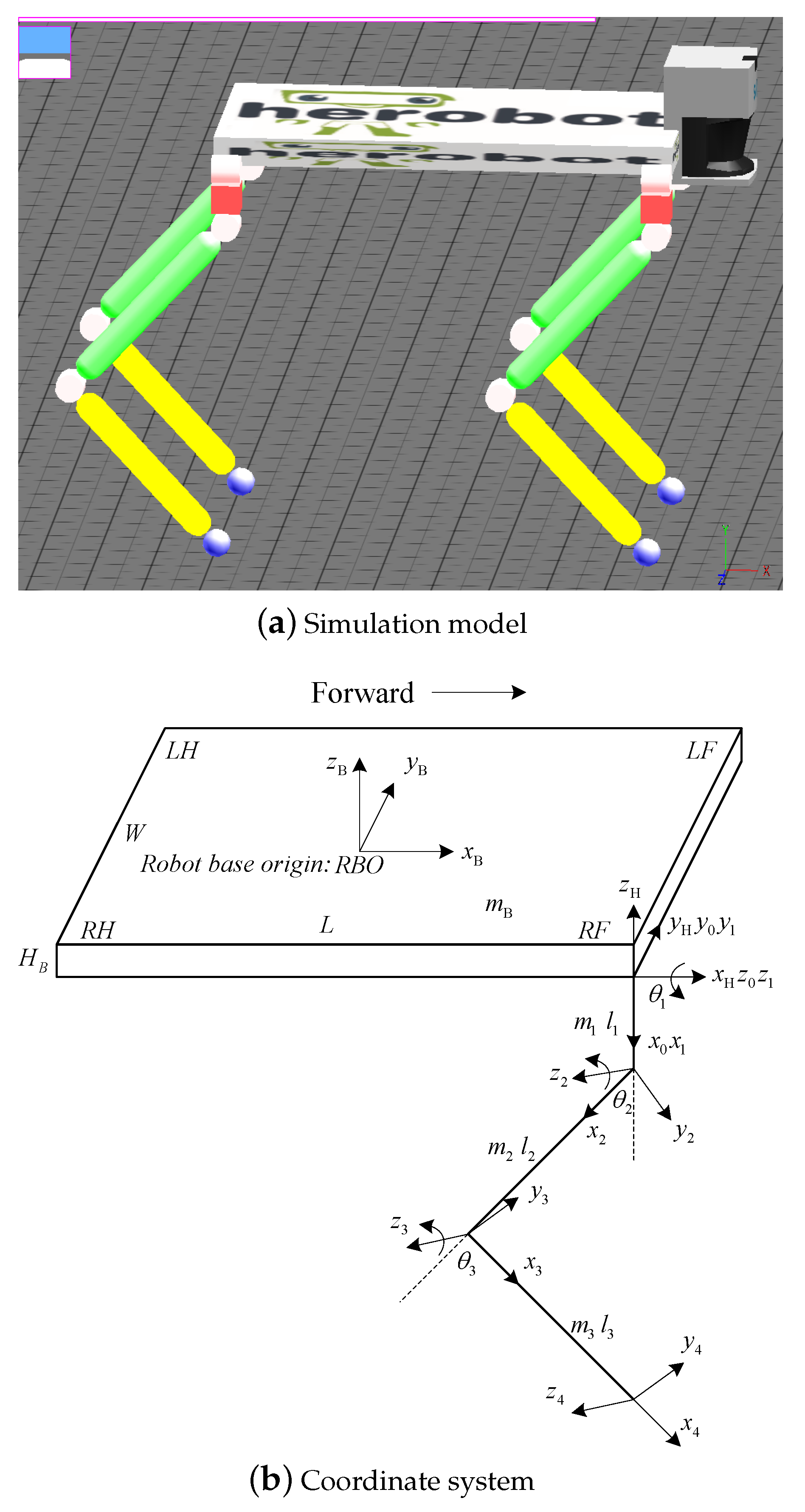
2. System Model of the Quadruped Robot
3. Three Stability-Guaranteed Static Gaits
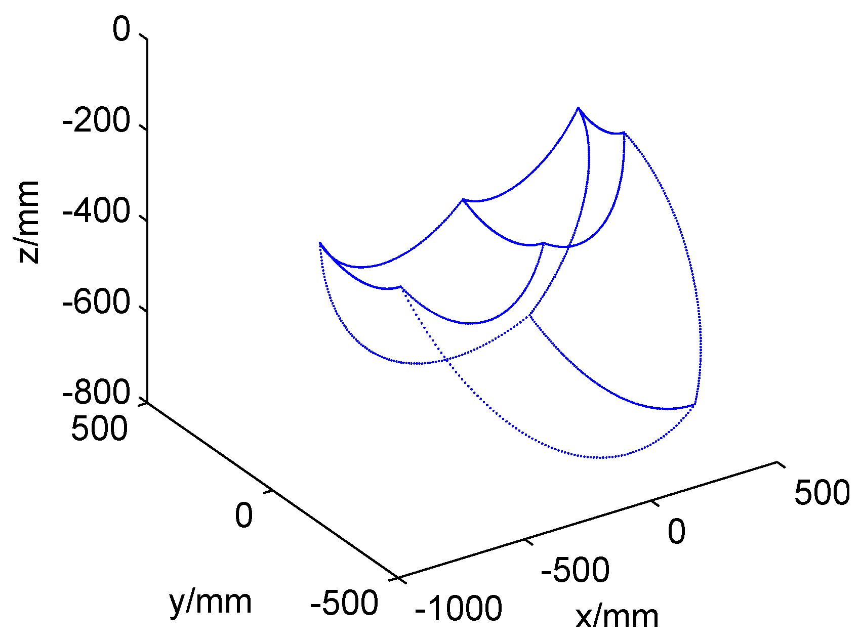
3.1. Workspace
3.2. Stability Margin
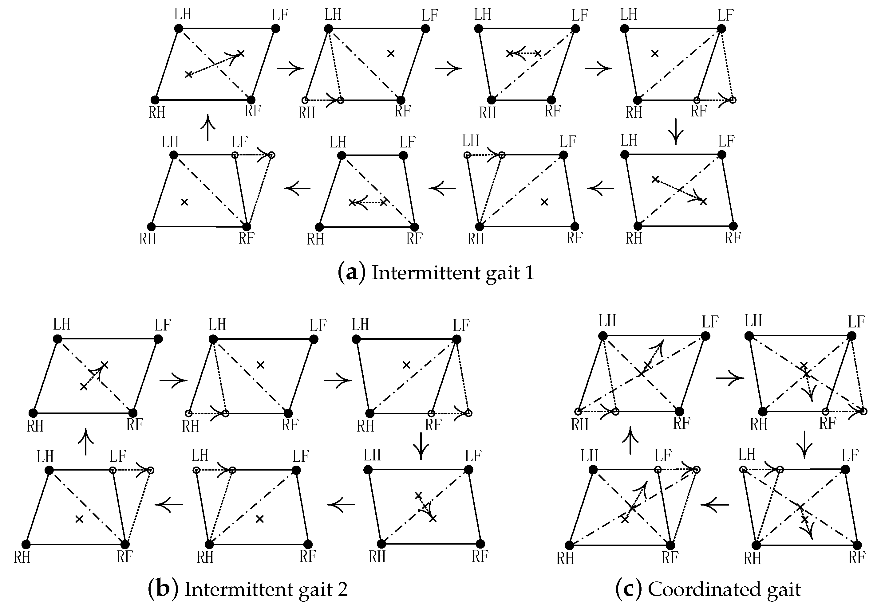
3.3. Three Stability-Guaranteed Static Gaits
4. High Terrain Adaptability
4.1. Gait Planning
4.1.1. Gait Planning on Even Terrain
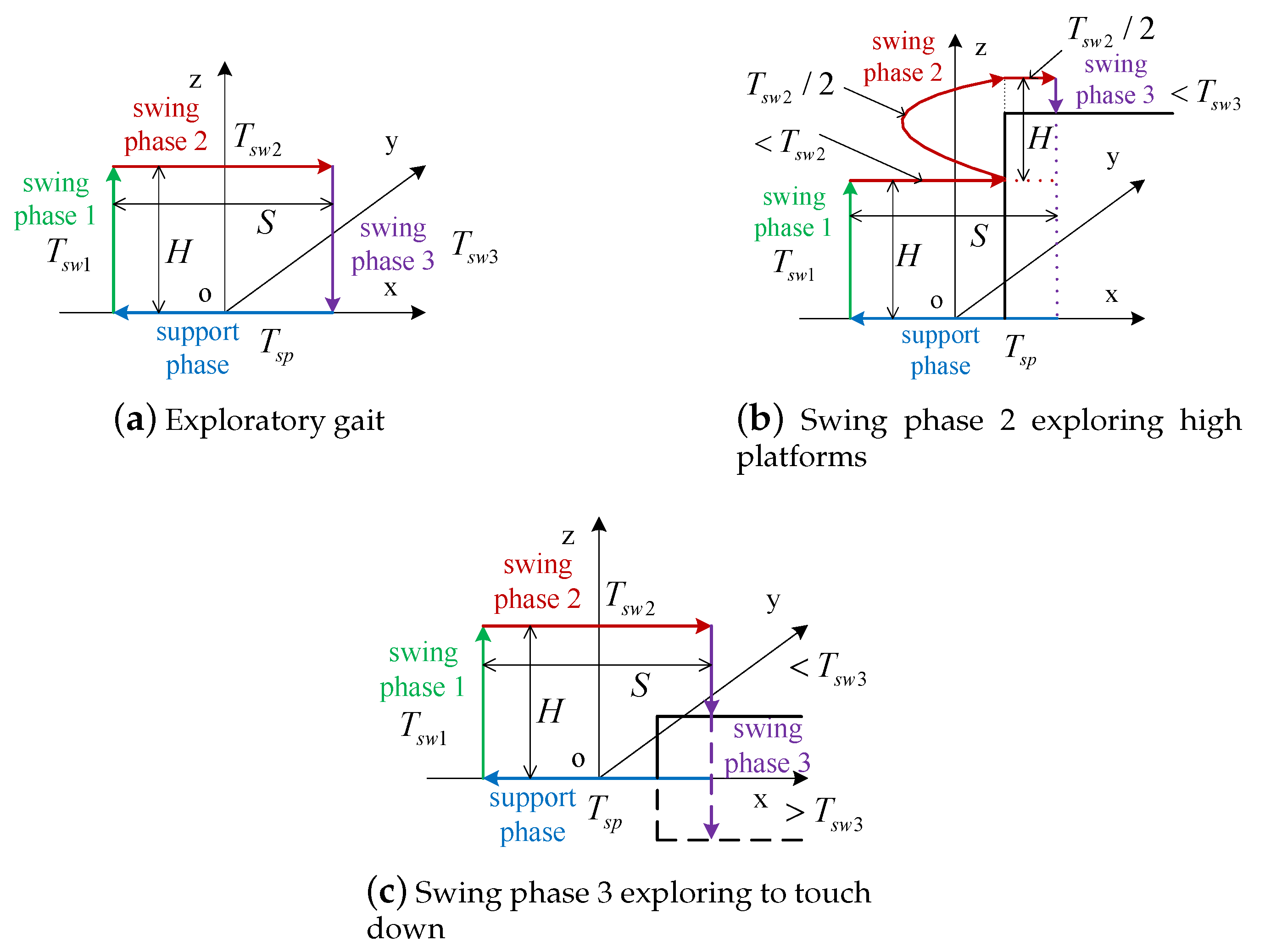
4.1.2. Exploratory Gait Planning on Uneven Terrain with Touch Sensing
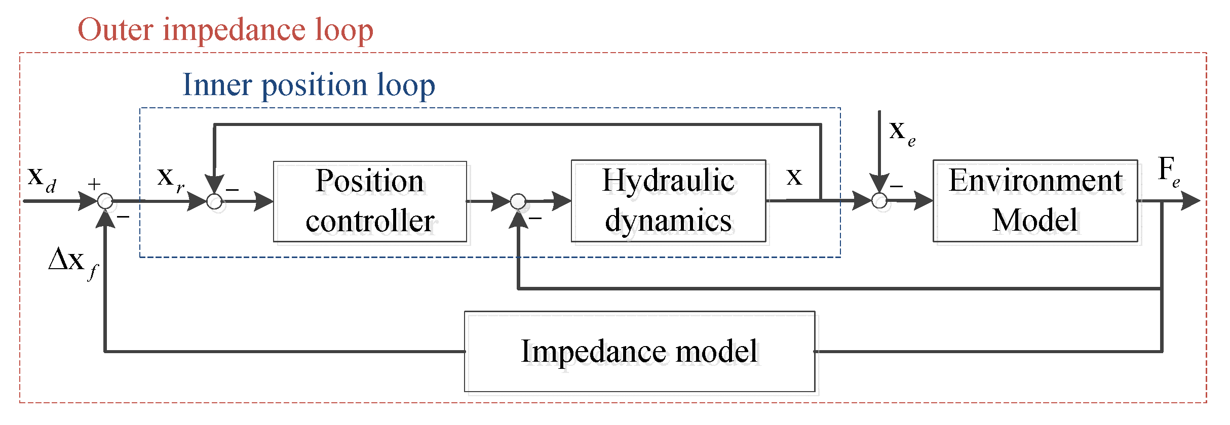
4.2. Position/Force Based Active Compliance Control
4.3. Attitude-Position Adjustment Strategy
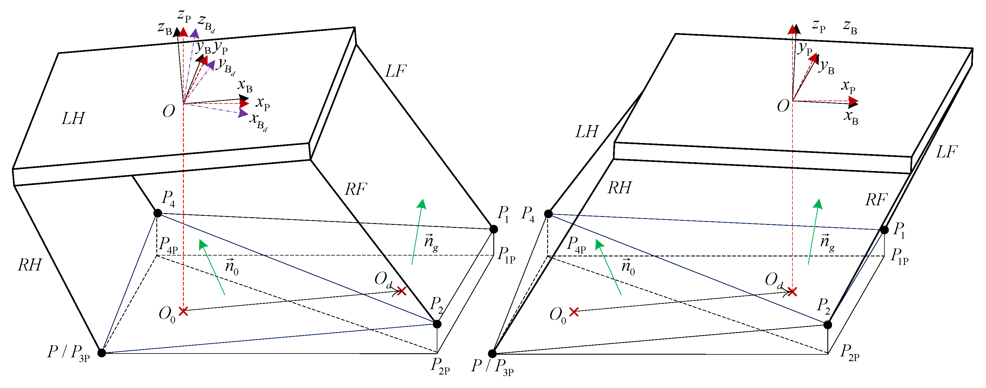
4.3.1. Terrain Estimation
4.3.2. Attitude Adjustment Strategy
4.3.3. Position Adjustment Strategy
5. Simulations
5.1. Performance Index
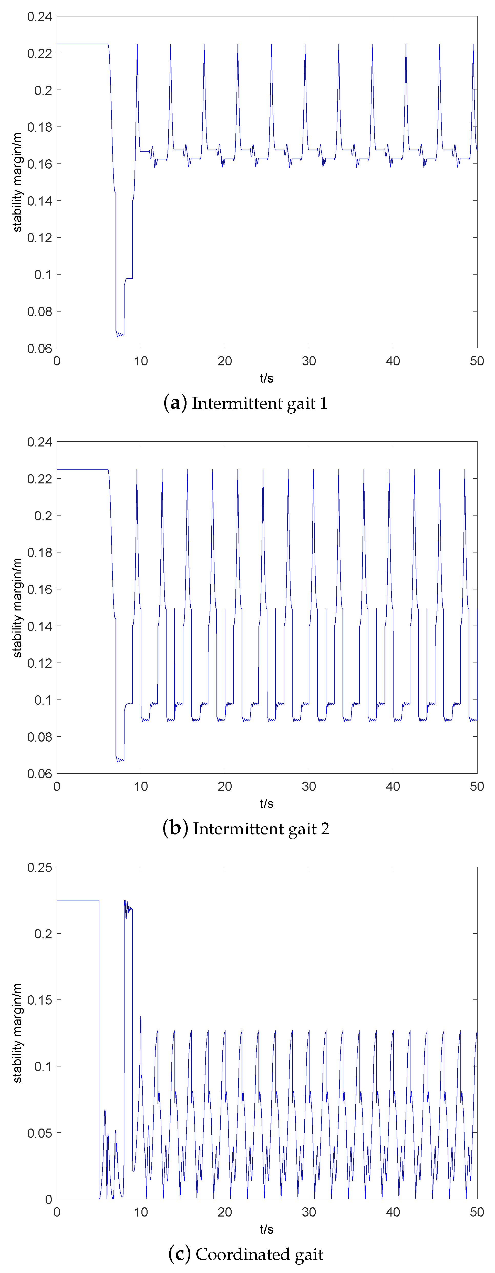
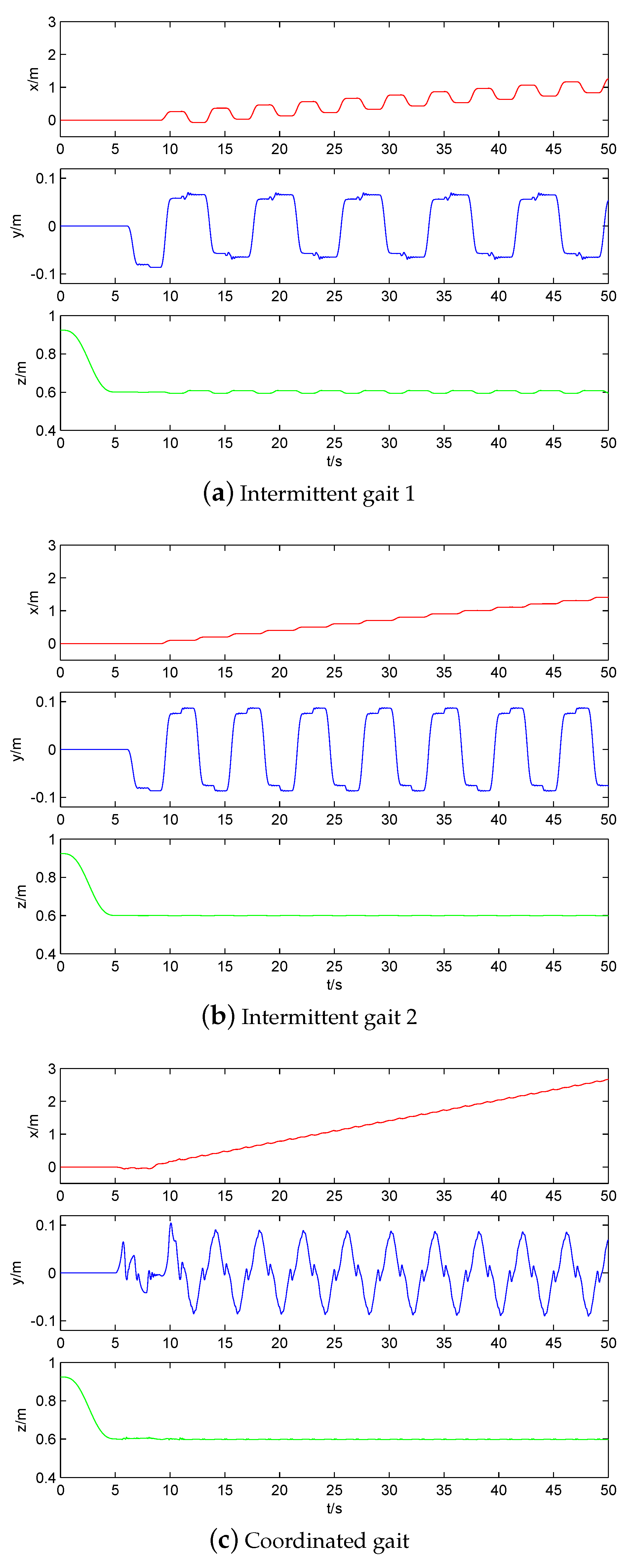
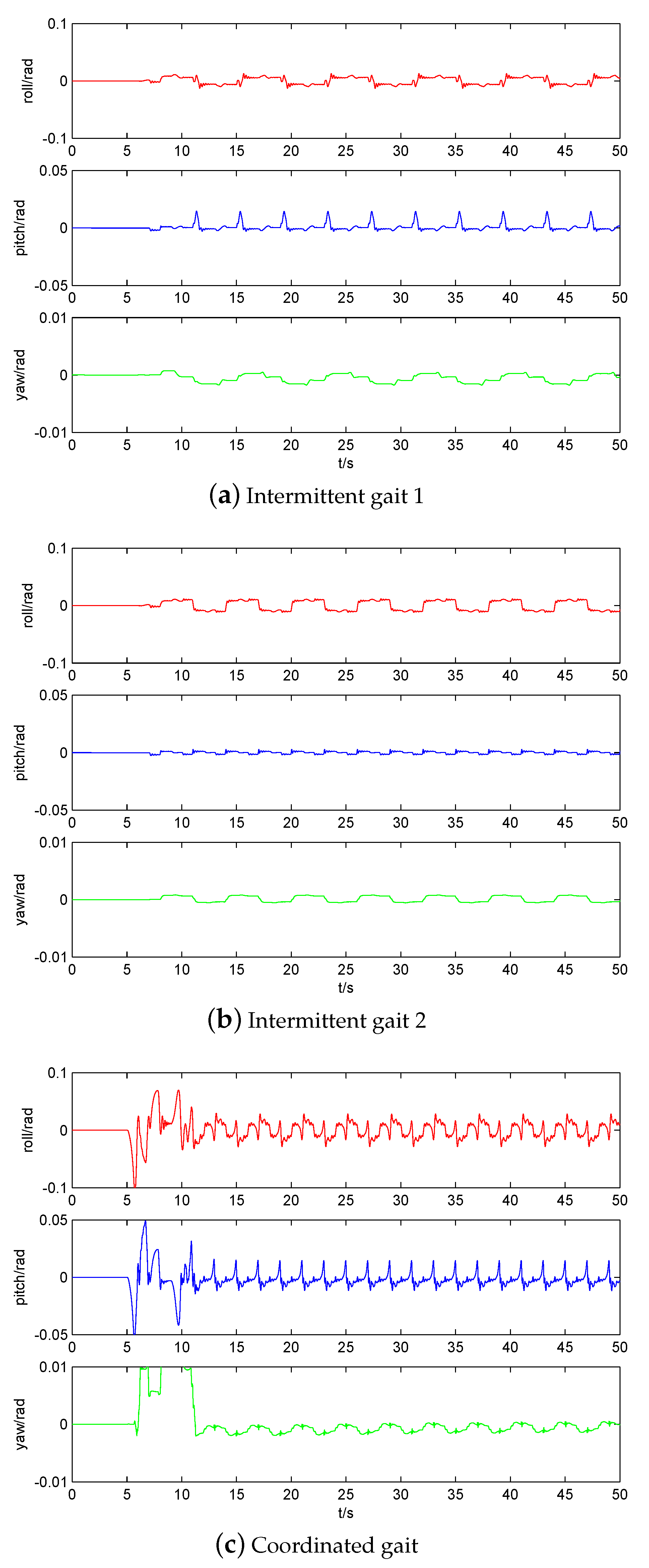
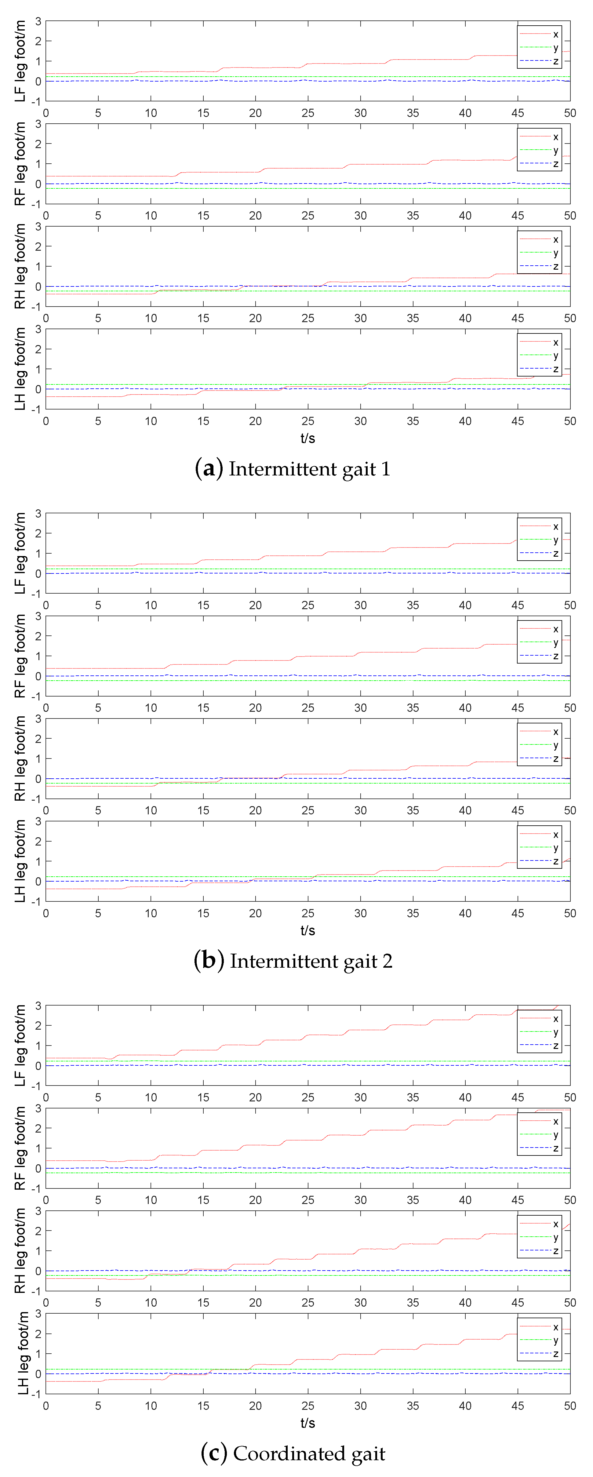
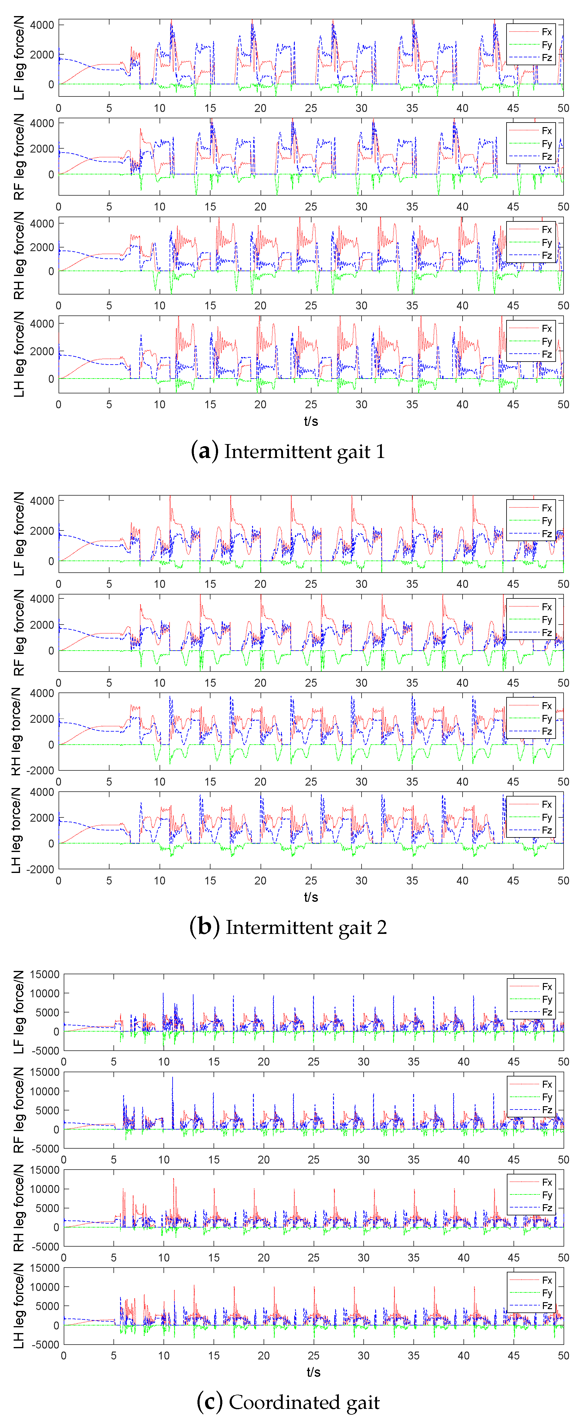
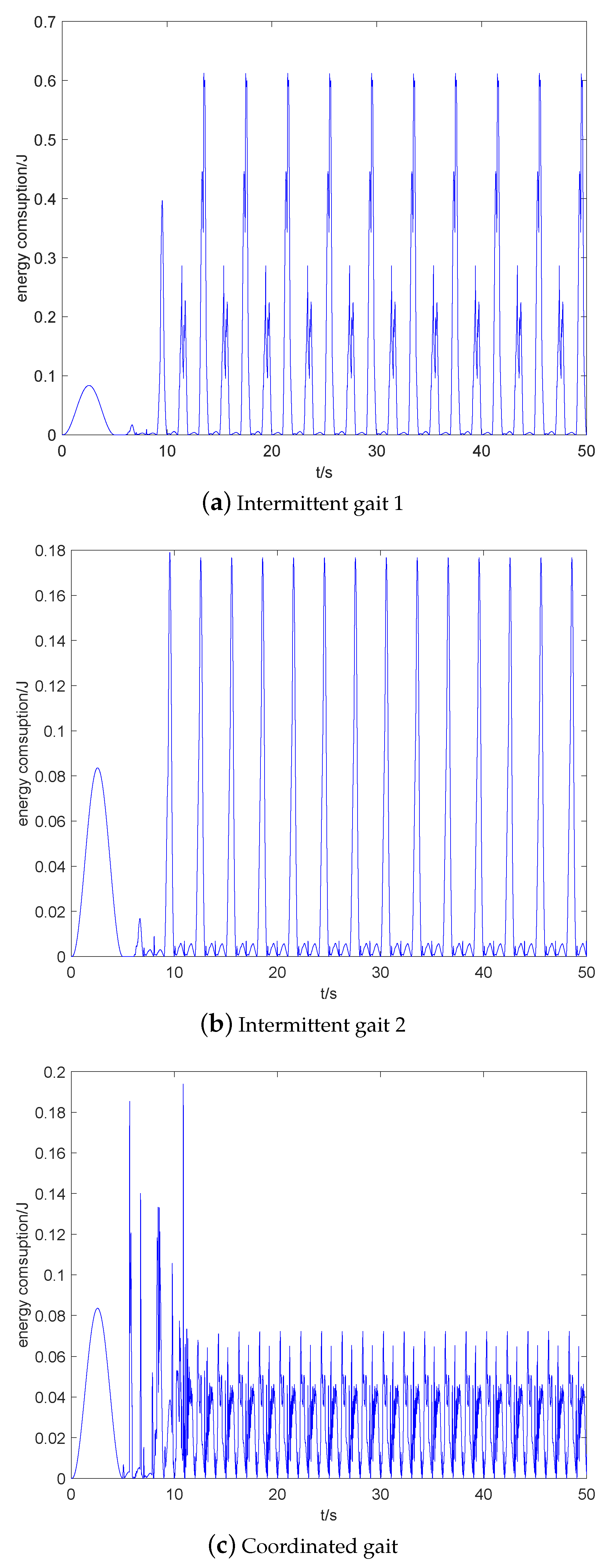
5.2. Three Static Gaits
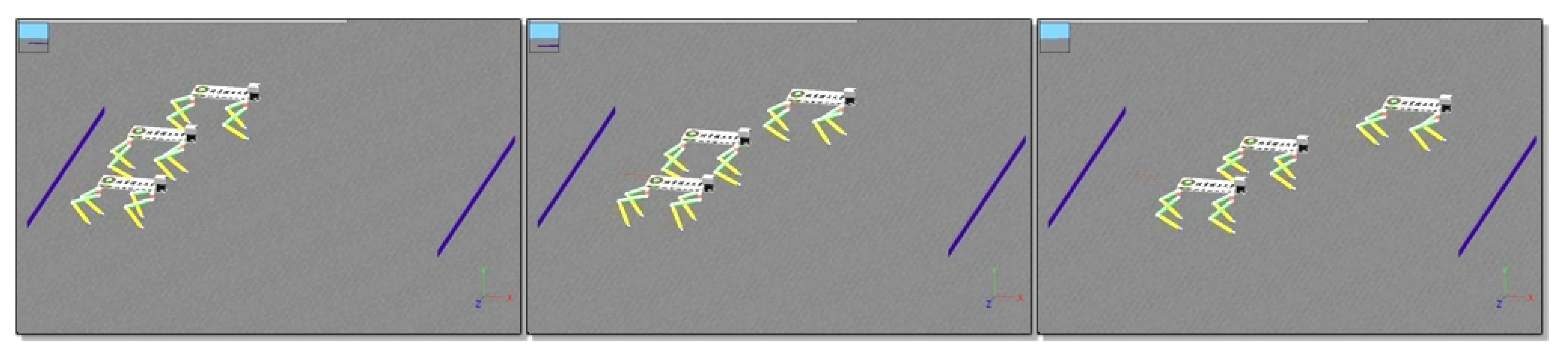
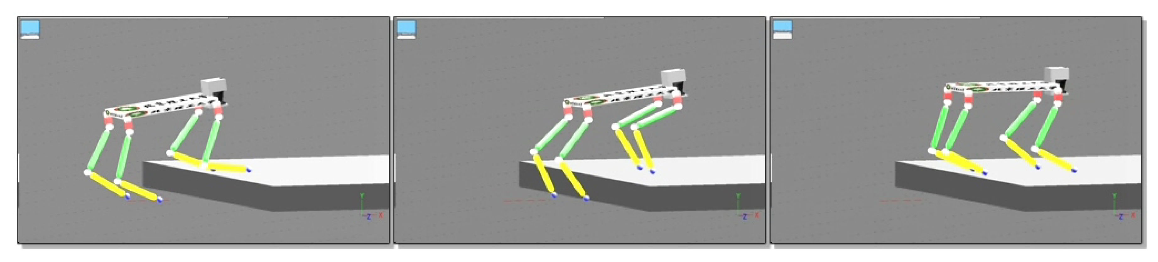
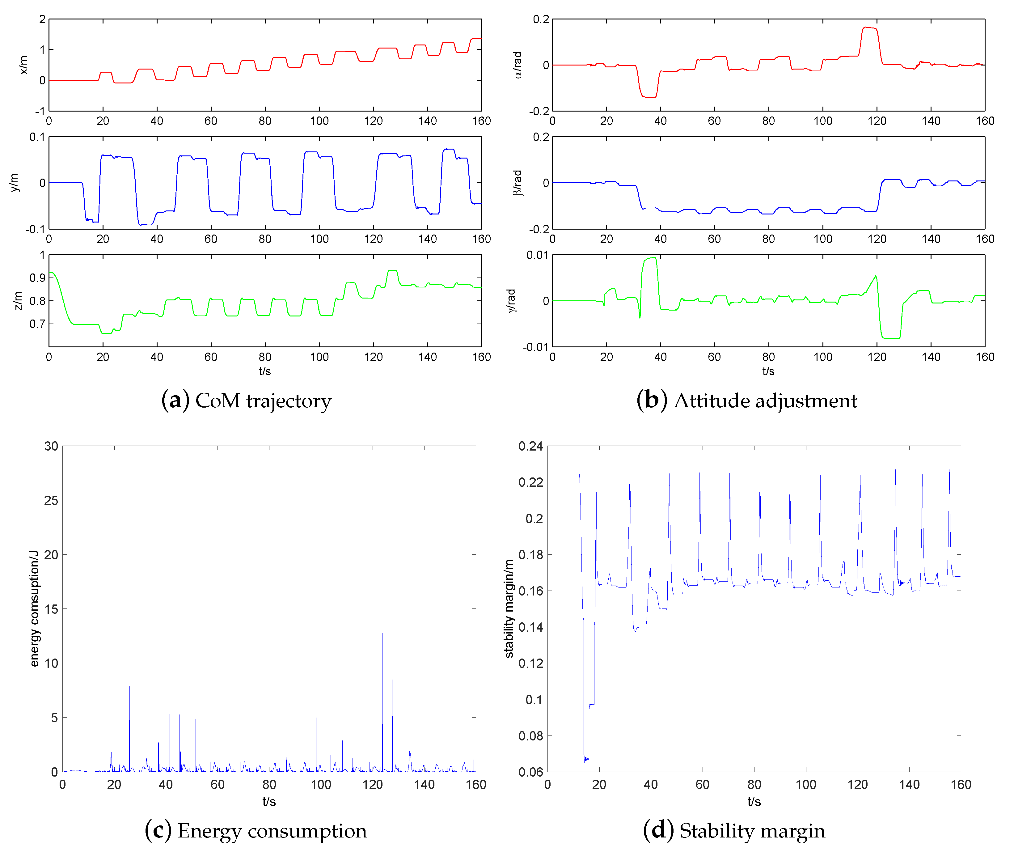
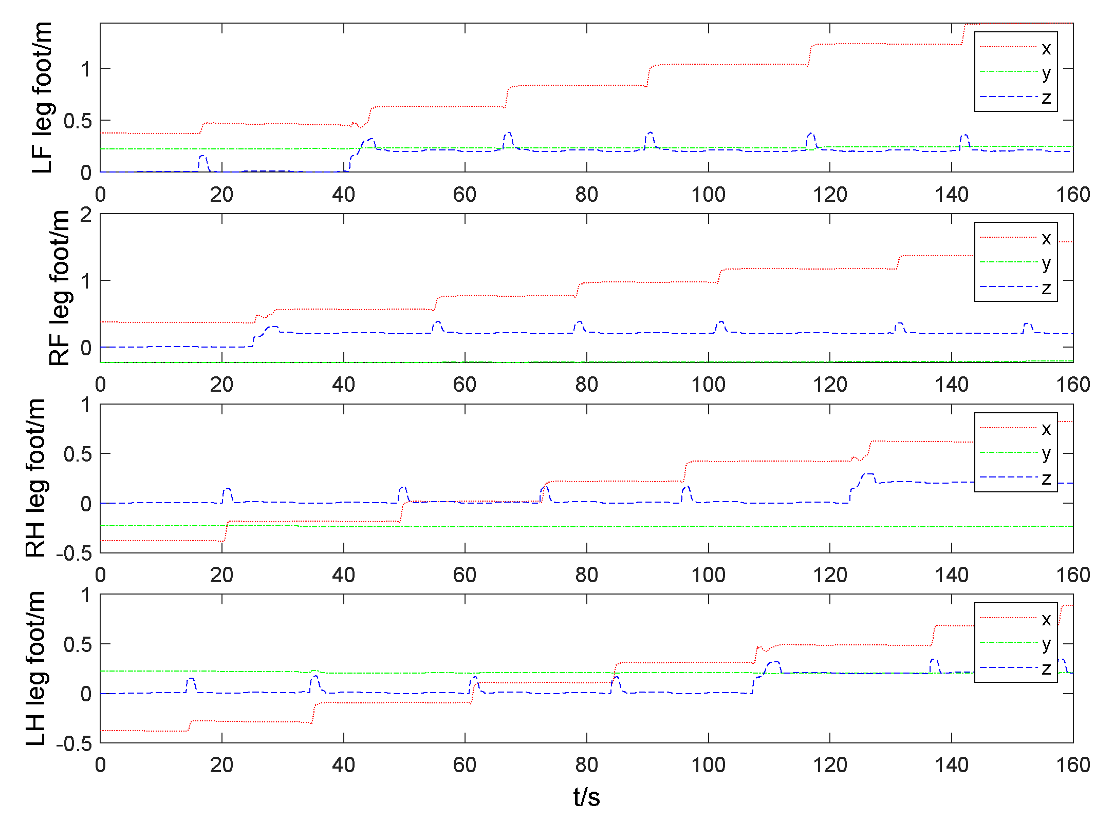
5.3. Walk on High Platform
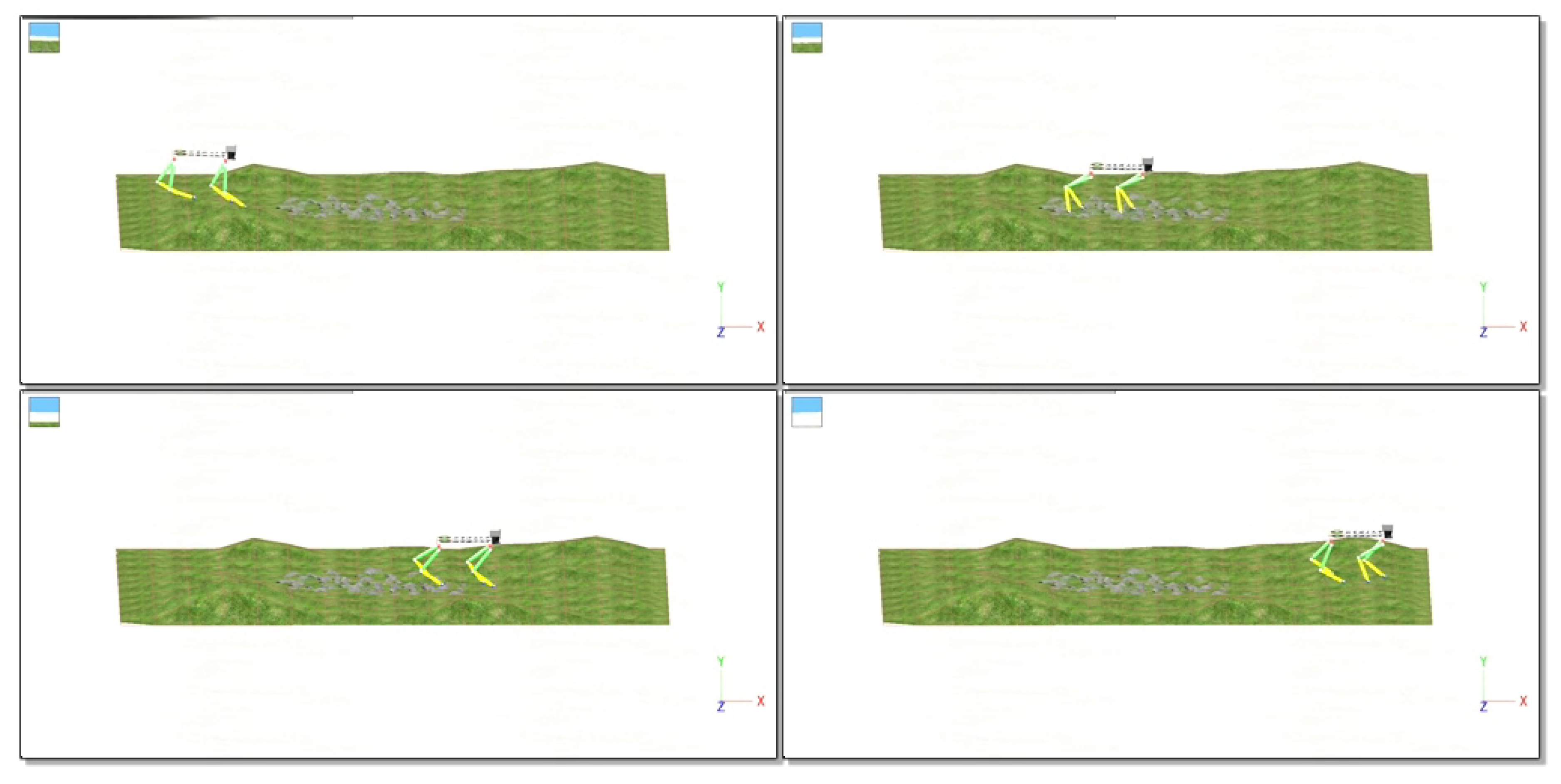
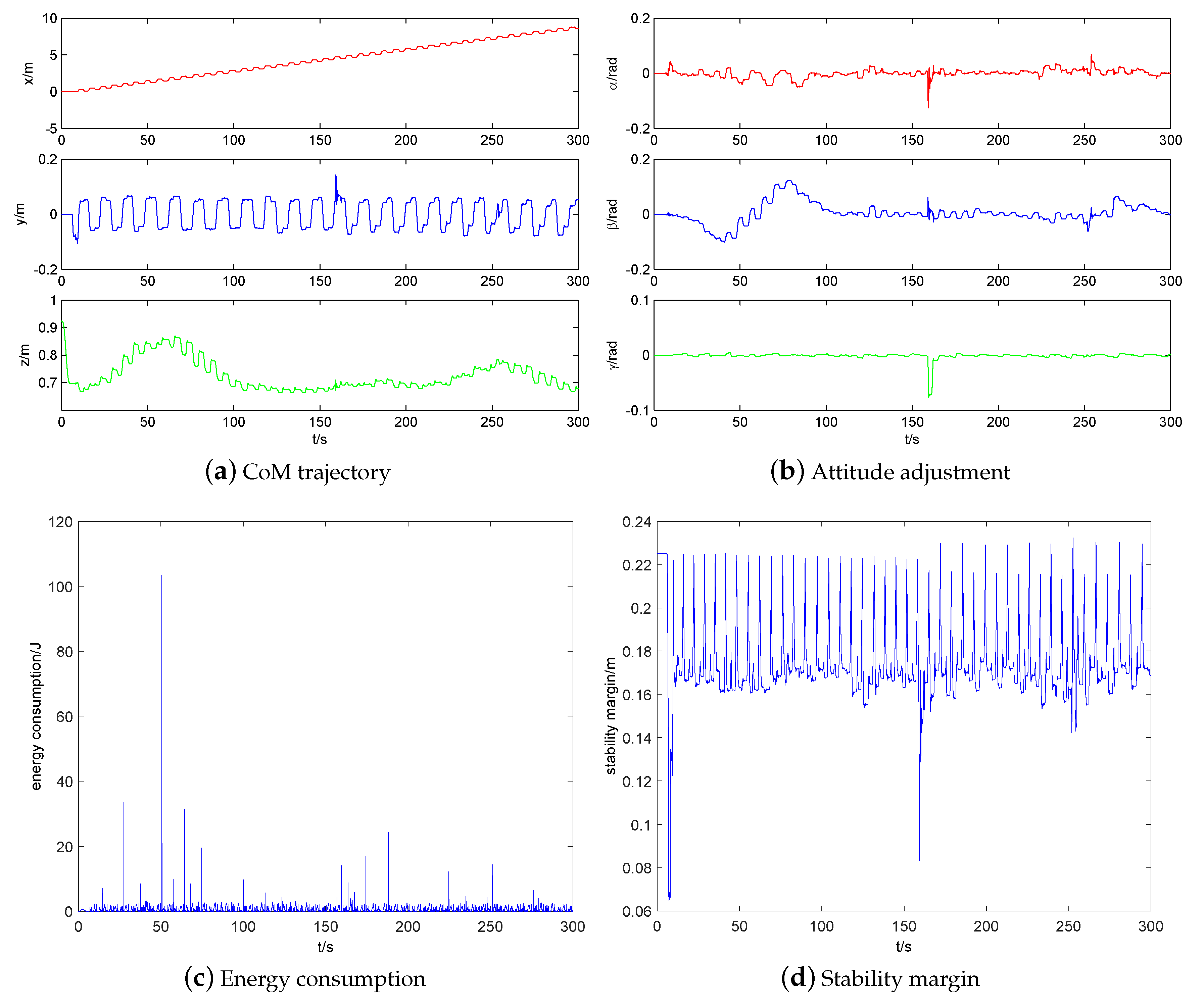
5.4. Walk on Uneven Terrain
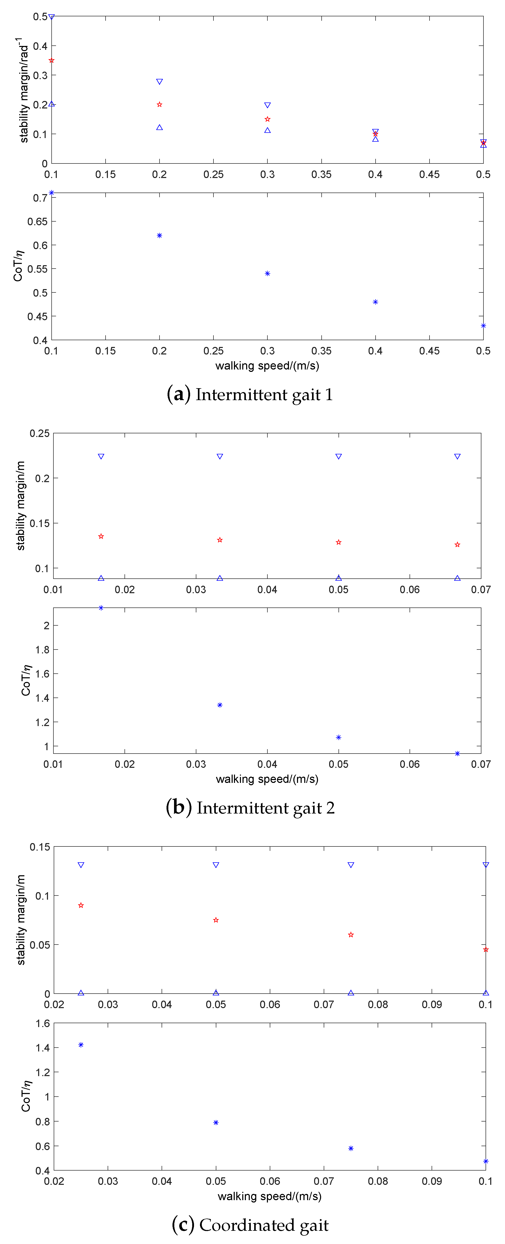
5.5. Performance Analysis
6. Conclusions
- Three stability-guaranteed static gaits: intermittent gait 1&2 and coordinated gait, are investigated, and a novel exploratory gait planning on uneven terrain with touch sensing is proposed to improve the terrain adaptability.
- A position/force based active compliance controller is introduced into static gaits to improve compliant behavior and energy efficiency of quadruped robots.
- A novel attitude-position adjustment strategy with terrain estimation is proposed to improve the walking stability.
- Proposed methods are validated by simulations, and the relationships among four factors for static gait selection: terrain complexity, stability, walking speed, and CoT are discussed.
Author Contributions
Funding
Acknowledgments
Conflicts of Interest
References
- Bai, L.; Hu, H.; Chen, X.; Sun, Y.; Ma, C.; Zhong, Y. CPG-Based Gait Generation of the Curved-Leg Hexapod Robot with Smooth Gait Transition. Sensors 2019, 19, 3705. [Google Scholar] [CrossRef]
- Liu, J.; Wang, P.; Zha, F.; Guo, W.; Sun, L. A Strong Tracking Mixed-Degree Cubature Kalman Filter Method and Its Application in a Quadruped Robot. Sensors 2020, 20, 2251. [Google Scholar] [CrossRef]
- Chen, G.; Wang, J.; Wang, L.; He, Y. Design and simulation of a hydraulic biped robot. In Proceedings of the IEEE Control Conference (CCC), 2013 32nd Chinese, Xi’an, China, 26–28 July 2013; pp. 4244–4249. [Google Scholar]
- Chen, G.; Hou, B.; Guo, S.; Wang, J. A Guide for Human Walking Model and Control—Insights from Mechanical Property Analysis of Human Walking. In Proceedings of the IEEE 2020 Chinese Control in addition, Decision Conference (CCDC), Hefei, China, 22–24 August 2020; pp. 4785–4790. [Google Scholar]
- Chen, G.; Guo, S.; Hou, B.; Wang, J. Virtual model control for quadruped robots. IEEE Access 2020, 8, 140736–140751. [Google Scholar] [CrossRef]
- Raibert, M.; Blankespoor, K.; Nelson, G.; Playter, R. Bigdog, the rough-terrain quadruped robot. IFAC Proc. Vol. 2008, 41, 10822–10825. [Google Scholar] [CrossRef]
- Semini, C.; Tsagarakis, N.G.; Guglielmino, E.; Focchi, M.; Cannella, F.; Caldwell, D.G. Design of HyQ—A hydraulically and electrically actuated quadruped robot. Proc. Inst. Mech. Eng. Part I J. Syst. Control. Eng. 2011, 225, 831–849. [Google Scholar] [CrossRef]
- Semini, C.; Barasuol, V.; Goldsmith, J.; Frigerio, M.; Focchi, M.; Gao, Y.; Caldwell, D.G. Design of the hydraulically actuated, torque-controlled quadruped robot HyQ2Max. IEEE/ASME Trans. Mechatronics 2016, 22, 635–646. [Google Scholar] [CrossRef]
- Hutter, M.; Gehring, C.; Bloesch, M.; Hoepflinger, M.A.; Remy, C.D.; Siegwart, R. StarlETH: A compliant quadrupedal robot for fast, efficient, and versatile locomotion. In Adaptive Mobile Robotics; World Scientific: Singapore, 2012; pp. 483–490. [Google Scholar]
- Hutter, M.; Gehring, C.; Jud, D.; Lauber, A.; Bellicoso, C.D.; Tsounis, V.; Hwangbo, J.; Bodie, K.; Fankhauser, P.; Bloesch, M.; et al. Anymal-a highly mobile and dynamic quadrupedal robot. In Proceedings of the 2016 IEEE/RSJ International Conference on Intelligent Robots and Systems (IROS), Daejeon, Korea, 9–14 October 2016; pp. 38–44. [Google Scholar]
- Hyun, D.J.; Seok, S.; Lee, J.; Kim, S. High speed trot-running: Implementation of a hierarchical controller using proprioceptive impedance control on the MIT Cheetah. Int. J. Robot. Res. 2014, 33, 1417–1445. [Google Scholar] [CrossRef]
- Park, H.W.; Wensing, P.M.; Kim, S. High-speed bounding with the MIT Cheetah 2: Control design and experiments. Int. J. Robot. Res. 2017, 36, 167–192. [Google Scholar] [CrossRef]
- Bledt, G.; Powell, M.J.; Katz, B.; Di Carlo, J.; Wensing, P.M.; Kim, S. MIT Cheetah 3: Design and control of a robust, dynamic quadruped robot. In Proceedings of the 2018 IEEE/RSJ International Conference on Intelligent Robots and Systems (IROS), Madrid, Spain, 1–5 October 2018; pp. 2245–2252. [Google Scholar]
- Spröwitz, A.; Tuleu, A.; Vespignani, M.; Ajallooeian, M.; Badri, E.; Ijspeert, A.J. Towards dynamic trot gait locomotion: Design, control, and experiments with Cheetah-cub, a compliant quadruped robot. Int. J. Robot. Res. 2013, 32, 932–950. [Google Scholar] [CrossRef]
- Blackman, D.J.; Nicholson, J.V.; Ordonez, C.; Miller, B.D.; Clark, J.E. Gait development on minitaur, a direct drive quadrupedal robot. In Proceedings of the Unmanned Systems Technology XVIII; International Society for Optics and Photonics: Bellingham, WA, USA, 2016; Volume 9837, p. 98370I. [Google Scholar]
- Unitree Co., L. AlienGo. 2019. Available online: http://www.unitree.cc/ (accessed on 17 July 2020).
- Ma, S.; Tomiyama, T.; Wada, H. Omnidirectional static walking of a quadruped robot. IEEE Trans. Robot. 2005, 21, 152–161. [Google Scholar] [CrossRef]
- Owaki, D.; Ishiguro, A. A quadruped robot exhibiting spontaneous gait transitions from walking to trotting to galloping. Sci. Rep. 2017, 7, 277. [Google Scholar] [CrossRef] [PubMed]
- Zhang, L.; Ma, S.; Honda, Y.; Inoue, K. Omnidirectional Static Walking of a Quadruped Robot on a Slope. J. Robot. Mechatronics 2006, 18, 51–58. [Google Scholar] [CrossRef]
- Hwangbo, J.; Lee, J.; Dosovitskiy, A.; Bellicoso, D.; Tsounis, V.; Koltun, V.; Hutter, M. Learning agile and dynamic motor skills for legged robots. Sci. Robot. 2019, 4, eaau5872. [Google Scholar] [CrossRef]
- Qi, S.; Quan, Q.; Jie, D.; Yu, H. A Quadruped Micro-Robot Based on Piezoelectric Driving. Sensors 2018, 18, 810. [Google Scholar] [CrossRef]
- Barasuol, V.; Buchli, J.; Semini, C.; Frigerio, M.; De Pieri, E.R.; Caldwell, D.G. A reactive controller framework for quadrupedal locomotion on challenging terrain. In Proceedings of the 2013 IEEE International Conference on Robotics and Automation, Karlsruhe, Germany, 6–10 May 2013; pp. 2554–2561. [Google Scholar]
- Wooden, D.; Malchano, M.; Blankespoor, K.; Howardy, A.; Rizzi, A.A.; Raibert, M. Autonomous navigation for BigDog. In Proceedings of the 2010 IEEE International Conference on Robotics and Automation, Anchorage, AK, USA, 3–7 May 2010; pp. 4736–4741. [Google Scholar]
- Hutter, M.; Sommer, H.; Gehring, C.; Hoepflinger, M.; Bloesch, M.; Siegwart, R. Quadrupedal locomotion using hierarchical operational space control. Int. J. Robot. Res. 2014, 33, 1047–1062. [Google Scholar] [CrossRef]
- Hua, N.; Ronglei, S.; Xiaofeng, H.; Xi, H. Static gait control for quadruped robot. In Proceedings of the International Conference on Intelligent Robotics and Applications; Springer: Berlin/Heidelberg, Germany, 2012; pp. 376–384. [Google Scholar]
- Focchi, M.; Del Prete, A.; Havoutis, I.; Featherstone, R.; Caldwell, D.G.; Semini, C. High-slope terrain locomotion for torque-controlled quadruped robots. Auton. Robot. 2017, 41, 259–272. [Google Scholar] [CrossRef]
- Li, X.; Gao, H.; Li, J.; Wang, Y.; Guo, Y. Hierarchically planning static gait for quadruped robot walking on rough terrain. J. Robot. 2019, 2019, 3153195. [Google Scholar] [CrossRef]
- Wilshin, S.; Reeve, M.A.; Haynes, G.C.; Revzen, S.; Koditschek, D.E.; Spence, A.J. Longitudinal quasi-static stability predicts changes in dog gait on rough terrain. J. Exp. Biol. 2017, 220, 1864–1874. [Google Scholar] [CrossRef]
- Luo, Q.; Gao, B.; Zhao, R. Study on the Static Gait of a Quadruped Robot Based on the Body Lateral Adjustment. In Proceedings of the International Conference on Intelligent Robotics and Applications; Springer: Cham, Switzerland, 2017; pp. 717–726. [Google Scholar]
- Zhang, C.; Dai, J.S. Continuous static gait with twisting trunk of a metamorphic quadruped robot. Mech. Sci. 2018, 9, 1–14. [Google Scholar] [CrossRef]
- Görner, M.; Stelzer, A. A leg proprioception based 6 DOF odometry for statically stable walking robots. Auton. Robot. 2013, 34, 311–326. [Google Scholar] [CrossRef]
- Zhang, S.; Liu, M.; Yin, Y.; Rong, X.; Li, Y.; Hua, Z. Static Gait Planning Method for Quadruped Robot walking on Unknown Rough Terrain. IEEE Access 2019, 7, 177651–177660. [Google Scholar] [CrossRef]
- Li, X.; Gao, H.; Zha, F.; Li, J.; Wang, Y.; Guo, Y.; Wang, X. Learning the Cost Function for Foothold Selection in a Quadruped Robot. Sensors 2019, 19, 1292. [Google Scholar] [CrossRef] [PubMed]
- Zhang, S.; Fan, M.; Li, Y.; Rong, X.; Liu, M. Generation of a continuous free gait for quadruped robot over rough terrains. Adv. Robot. 2019, 33, 74–89. [Google Scholar] [CrossRef]
- Yi, S. Reliable gait planning and control for miniaturized quadruped robot pet. Mechatronics 2010, 20, 485–495. [Google Scholar] [CrossRef]
- Koivumäki, J.; Mattila, J. Stability-guaranteed impedance control of hydraulic robotic manipulators. IEEE/ASME Trans. Mechatronics 2016, 22, 601–612. [Google Scholar] [CrossRef]
- Guangrong, C.; Junzheng, W.; Jiangbo, Z.; Liling, M.; Wei, S. Stable Impedance Control of a Single Leg of Hydraulic Legged Robot Based on Virtual Decomposition Control. ROBOT 2017, 39, 704–714. [Google Scholar]
- Chen, G.; Wang, J.; Wang, S.; Zhao, J.; Shen, W. Indirect adaptive robust dynamic surface control in separate meter-in and separate meter-out control system. Nonlinear Dyn. 2017, 90, 951–970. [Google Scholar] [CrossRef]
- Chen, G.; Wang, J.; Wang, S.; Zhao, J.; Shen, W.; Li, J. Application of a new adaptive robust controller design method to electro-hydraulic servo system. Acta Autom. Sin. 2016, 42, 375–384. [Google Scholar]
- Ba, K.X.; Yu, B.; Ma, G.L.; Gao, Z.J.; Zhu, Q.X.; Jin, Z.G.; Kong, X.D. Dynamic Compliance Analysis for LHDS of Legged Robot, Part A: Position-Based Impedance Control. IEEE Access 2018, 6, 64321–64332. [Google Scholar] [CrossRef]
- Ba, K.; Yu, B.; Gao, Z.; Zhu, Q.; Ma, G.; Kong, X. Dynamic Compliance Analysis for LHDS of Legged Robot, Part B: Force-Based Impedance Control. IEEE Access 2018, 6, 74799–74811. [Google Scholar] [CrossRef]
- Chen, G.; Wang, J.; Wang, S.; Zhao, J.; Shen, W. Compliance control for a hydraulic bouncing system. ISA Trans. 2018, 79, 232–238. [Google Scholar] [CrossRef]
- Chen, G.; Guo, S.; Hou, B.; Wang, J. Compliance Control and Analysis for Equivalent Hydraulic Legs. IEEE Access 2020, 8, 145661–145671. [Google Scholar] [CrossRef]
- Wu, J.; Zhang, D.; Liu, J.; Han, X. A moment approach to positioning accuracy reliability analysis for industrial robots. IEEE Trans. Reliab. 2020, 69, 699–714. [Google Scholar] [CrossRef]
- Rocha, C.; Tonetto, C.; Dias, A. A comparison between the Denavit–Hartenberg and the screw-based methods used in kinematic modeling of robot manipulators. Robot. Comput. Integr. Manuf. 2011, 27, 723–728. [Google Scholar] [CrossRef]
- Corke, P.I. A simple and systematic approach to assigning Denavit–Hartenberg parameters. IEEE Trans. Robot. 2007, 23, 590–594. [Google Scholar] [CrossRef]
- Chen, G.; Wang, J.; Wang, L. Gait planning and compliance control of a biped robot on stairs with desired ZMP. IFAC Proc. Vol. 2014, 47, 2165–2170. [Google Scholar] [CrossRef]
- Zhao, Y.; Gao, F.; Zhao, Y.; Chen, Z. Peg-in-Hole Assembly Based on Six-Legged Robots with Visual Detecting and Force Sensing. Sensors 2020, 20, 2861. [Google Scholar] [CrossRef]
- Chen, G.; Guo, S.; Hou, B.; Wang, J. Fractional Order Impedance Control. IEEE Access 2020, 8, 48904–48916. [Google Scholar] [CrossRef]
- Zhang, L.; Wang, F.; Gao, Z.; Gao, S.; Li, C. Research on the Stationarity of Hexapod Robot Posture Adjustment. Sensors 2020, 20, 2859. [Google Scholar] [CrossRef]
- Cunningham, C.; Schilling, N.; Anders, C.; Carrier, D. The influence of foot posture on the cost of transport in humans. J. Exp. Biol. 2010, 213, 790–797. [Google Scholar] [CrossRef]
- Zhang, L.; Gao, S. Normalized energy stability margin based analysis of omni-directional static walking of a quadruped robot on rough terrain. In Proceedings of the Advanced Materials Research; Trans Tech Publications Ltd.: Kapellweg, Switzerland, 2012; Volume 383, pp. 7401–7405. [Google Scholar]


| Parameters | Value |
|---|---|
| 0.08 m, 0.41 m, 0.43 m | |
| (Body height) | 1.1 m, 0.57 m, 1.08 m |
| 1 kg, 2 kg, 2 kg, 50 kg | |
| Walking height | 0.45 m ∼ 0.83 m |
| Mass, Load | 60 kg, 300 kg |
| 0.2 m, 0.05 m, 1 s |
| Simulations | Links |
|---|---|
| There static gait on even terrain | https://youtu.be/V0yh1IJxOmk |
| high platform with m height | https://youtu.be/FM_4M2dytno |
| uneven terrain | https://youtu.be/-fPBTk_APX8 |
| stairs with m height | https://youtu.be/dLgKdVpJlo0 |
| rad slope with impedance control | https://youtu.be/nL815_TEYh4 |
| rad slope without impedance control | https://youtu.be/v1mqAgksb4Q |
© 2020 by the authors. Licensee MDPI, Basel, Switzerland. This article is an open access article distributed under the terms and conditions of the Creative Commons Attribution (CC BY) license (http://creativecommons.org/licenses/by/4.0/).
Share and Cite
Hao, Q.; Wang, Z.; Wang, J.; Chen, G. Stability-Guaranteed and High Terrain Adaptability Static Gait for Quadruped Robots. Sensors 2020, 20, 4911. https://doi.org/10.3390/s20174911
Hao Q, Wang Z, Wang J, Chen G. Stability-Guaranteed and High Terrain Adaptability Static Gait for Quadruped Robots. Sensors. 2020; 20(17):4911. https://doi.org/10.3390/s20174911
Chicago/Turabian StyleHao, Qian, Zhaoba Wang, Junzheng Wang, and Guangrong Chen. 2020. "Stability-Guaranteed and High Terrain Adaptability Static Gait for Quadruped Robots" Sensors 20, no. 17: 4911. https://doi.org/10.3390/s20174911
APA StyleHao, Q., Wang, Z., Wang, J., & Chen, G. (2020). Stability-Guaranteed and High Terrain Adaptability Static Gait for Quadruped Robots. Sensors, 20(17), 4911. https://doi.org/10.3390/s20174911